engine FORD FLEX 2010 1.G Workshop Manual
[x] Cancel search | Manufacturer: FORD, Model Year: 2010, Model line: FLEX, Model: FORD FLEX 2010 1.GPages: 397
Page 291 of 397
Maintenance and Modifications
The suspension and steering systems on your vehicle have been designed
and tested to provide predictable performance whether loaded or empty
and durable load carrying capability. For this reason, Ford Motor
Company strongly recommends that you do not make modifications such
as adding or removing parts (such as lift kits or stabilizer bars) or by
using replacement parts not equivalent to the original factory equipment.
Any modifications to a vehicle that raise the center of gravity can make
it more likely the vehicle will rollover as a result of a loss of control.
Ford Motor Company recommends that caution be used with any vehicle
equipped with a high load or device (such as ladder or luggage racks).
Failure to maintain your vehicle properly may void the warranty, increase
your repair cost, reduce vehicle performance and operational capabilities
and adversely affect driver and passenger safety. Frequent inspection of
vehicle chassis components is recommended if the vehicle is subjected to
heavy off-highway usage.
DRIVING THROUGH WATER
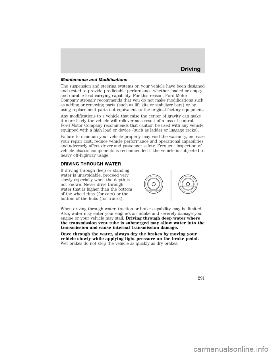
If driving through deep or standing
water is unavoidable, proceed very
slowly especially when the depth is
not known. Never drive through
water that is higher than the bottom
of the wheel rims (for cars) or the
bottom of the hubs (for trucks).
When driving through water, traction or brake capability may be limited.
Also, water may enter your engine’s air intake and severely damage your
engine or your vehicle may stall.Driving through deep water where
the transmission vent tube is submerged may allow water into the
transmission and cause internal transmission damage.
Once through the water, always dry the brakes by moving your
vehicle slowly while applying light pressure on the brake pedal.
Wet brakes do not stop the vehicle as quickly as dry brakes.
Driving
291
2010 Flex(471)
Owners Guide, 1st Printing
USA(fus)
Page 294 of 397
FUEL PUMP SHUT-OFF
In the event of a moderate to severe collision, this vehicle is equipped
with a fuel pump shut-off feature that stops the flow of fuel to the
engine. Not every impact will cause a shut-off.
Should your vehicle shut off after a collision due to this feature, you may
restart your vehicle by doing the following:
1. Turn the ignition switch to the off position.
2. Turn the ignition switch to the on position.
In some instances the vehicle may not restart the first time you try to
restart and may take one additional attempt.
WARNING:Failure to inspect and if necessary repair fuel leaks
after a collision may increase the risk of fire and serious injury.
Ford Motor Company recommends that the fuel system be inspected
by an authorized dealer after any collision.
FUSES AND RELAYS
Fuses
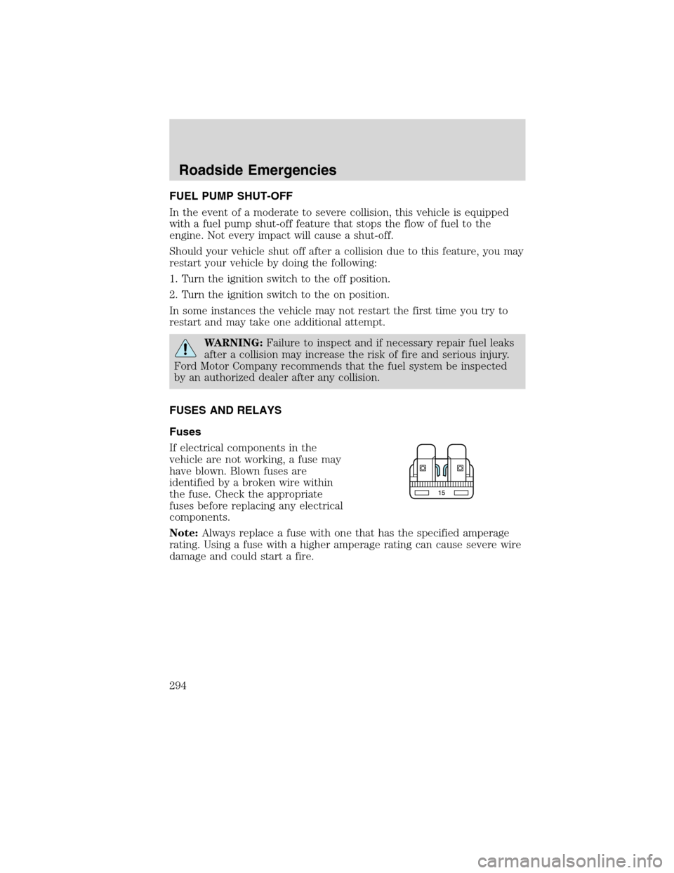
If electrical components in the
vehicle are not working, a fuse may
have blown. Blown fuses are
identified by a broken wire within
the fuse. Check the appropriate
fuses before replacing any electrical
components.
Note:Always replace a fuse with one that has the specified amperage
rating. Using a fuse with a higher amperage rating can cause severe wire
damage and could start a fire.
15
Roadside Emergencies
294
2010 Flex(471)
Owners Guide, 1st Printing
USA(fus)
Page 298 of 397
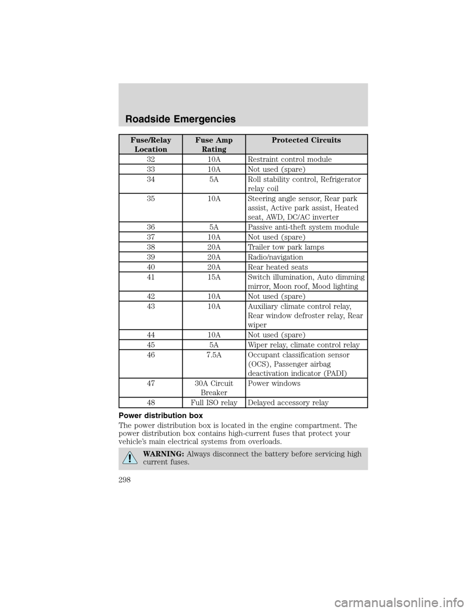
Fuse/Relay
LocationFuse Amp
RatingProtected Circuits
32 10A Restraint control module
33 10A Not used (spare)
34 5A Roll stability control, Refrigerator
relay coil
35 10A Steering angle sensor, Rear park
assist, Active park assist, Heated
seat, AWD, DC/AC inverter
36 5A Passive anti-theft system module
37 10A Not used (spare)
38 20A Trailer tow park lamps
39 20A Radio/navigation
40 20A Rear heated seats
41 15A Switch illumination, Auto dimming
mirror, Moon roof, Mood lighting
42 10A Not used (spare)
43 10A Auxiliary climate control relay,
Rear window defroster relay, Rear
wiper
44 10A Not used (spare)
45 5A Wiper relay, climate control relay
46 7.5A Occupant classification sensor
(OCS), Passenger airbag
deactivation indicator (PADI)
47 30A Circuit
BreakerPower windows
48 Full ISO relay Delayed accessory relay
Power distribution box
The power distribution box is located in the engine compartment. The
power distribution box contains high-current fuses that protect your
vehicle’s main electrical systems from overloads.
WARNING:Always disconnect the battery before servicing high
current fuses.
Roadside Emergencies
298
2010 Flex(471)
Owners Guide, 1st Printing
USA(fus)
Page 301 of 397
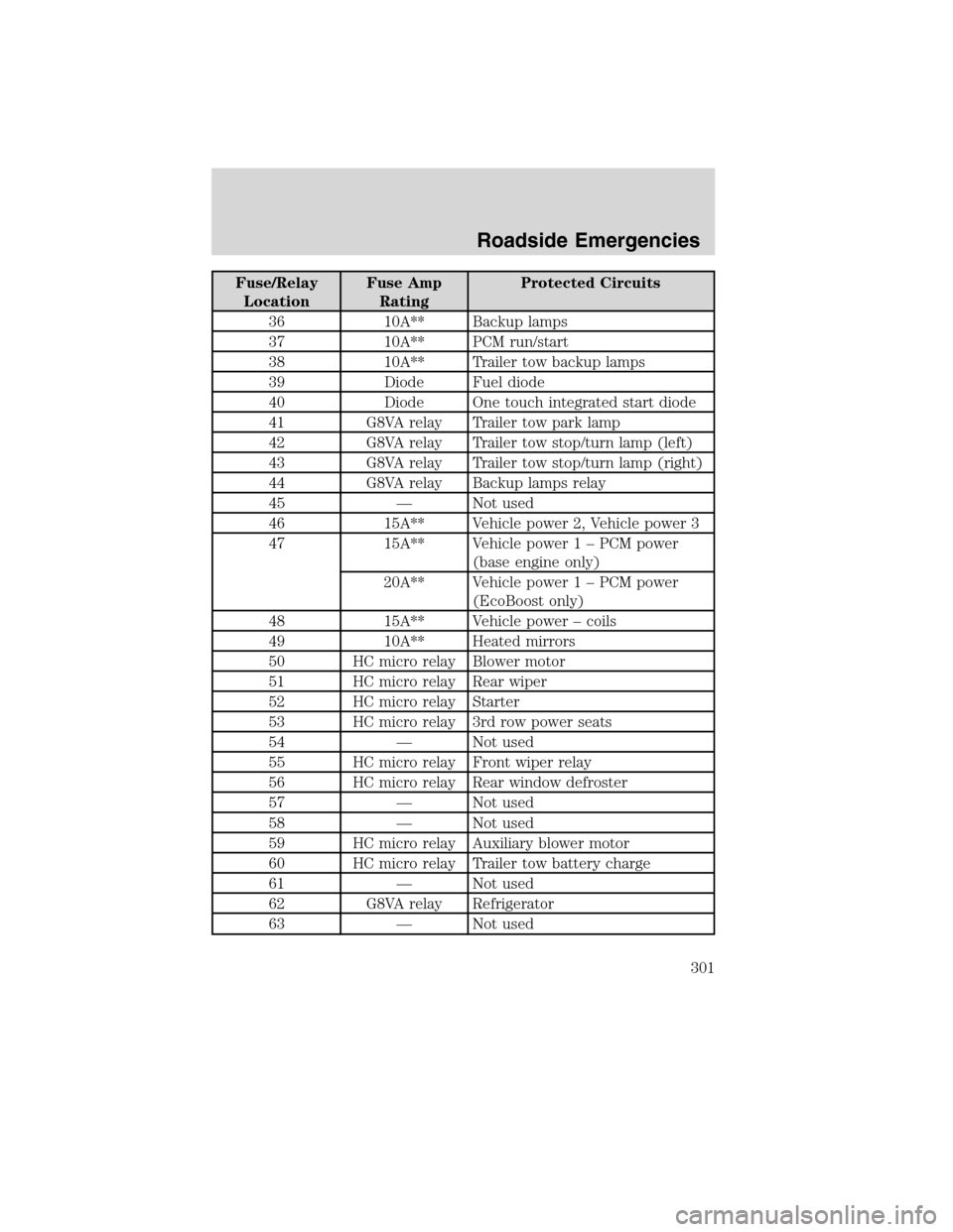
Fuse/Relay
LocationFuse Amp
RatingProtected Circuits
36 10A** Backup lamps
37 10A** PCM run/start
38 10A** Trailer tow backup lamps
39 Diode Fuel diode
40 Diode One touch integrated start diode
41 G8VA relay Trailer tow park lamp
42 G8VA relay Trailer tow stop/turn lamp (left)
43 G8VA relay Trailer tow stop/turn lamp (right)
44 G8VA relay Backup lamps relay
45 — Not used
46 15A** Vehicle power 2, Vehicle power 3
47 15A** Vehicle power 1 – PCM power
(base engine only)
20A** Vehicle power 1 – PCM power
(EcoBoost only)
48 15A** Vehicle power – coils
49 10A** Heated mirrors
50 HC micro relay Blower motor
51 HC micro relay Rear wiper
52 HC micro relay Starter
53 HC micro relay 3rd row power seats
54 — Not used
55 HC micro relay Front wiper relay
56 HC micro relay Rear window defroster
57 — Not used
58 — Not used
59 HC micro relay Auxiliary blower motor
60 HC micro relay Trailer tow battery charge
61 — Not used
62 G8VA relay Refrigerator
63 — Not used
Roadside Emergencies
301
2010 Flex(471)
Owners Guide, 1st Printing
USA(fus)
Page 304 of 397
•Use snow chains on the end of the vehicle with the dissimilar spare
tire/wheel
The usage of a full-size dissimilar spare tire/wheel can lead to
impairment of the following:
•Handling, stability and braking performance
•Comfort and noise
•Ground clearance and parking at curbs
•Winter weather driving capability
•Wet weather driving capability
•All-Wheel driving capability (if applicable)
•Load leveling adjustment (if applicable)
When driving with the full-size dissimilar spare tire/wheel additional
caution should be given to:
•Towing a trailer
•Driving vehicles equipped with a camper body
•Driving vehicles with a load on the cargo rack
Drive cautiously when using a full-size dissimilar spare tire/wheel and
seek service as soon as possible.
Stopping and securing the vehicle
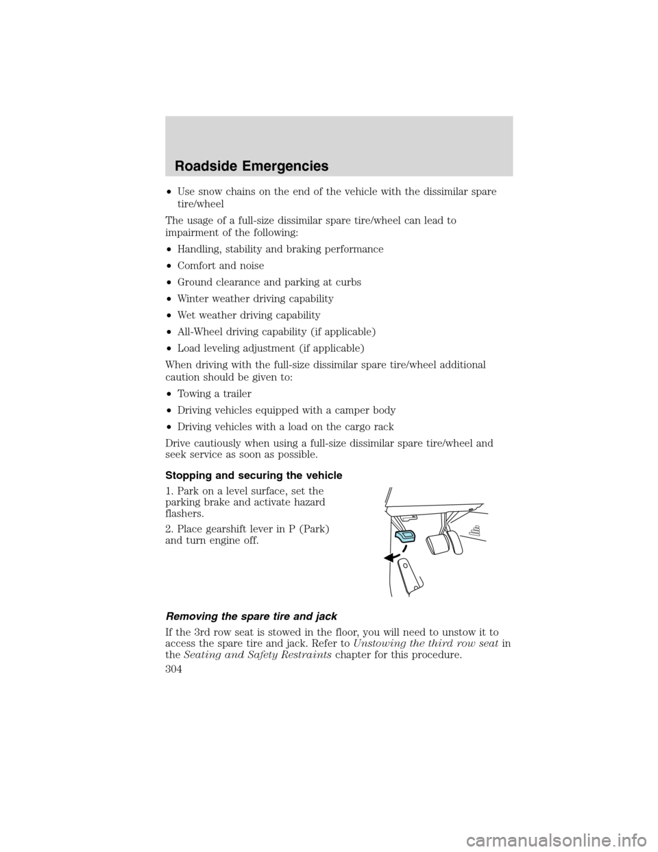
1. Park on a level surface, set the
parking brake and activate hazard
flashers.
2. Place gearshift lever in P (Park)
and turn engine off.
Removing the spare tire and jack
If the 3rd row seat is stowed in the floor, you will need to unstow it to
access the spare tire and jack. Refer toUnstowing the third row seatin
theSeating and Safety Restraintschapter for this procedure.
Roadside Emergencies
304
2010 Flex(471)
Owners Guide, 1st Printing
USA(fus)
Page 311 of 397
•Read the information in theTips for use of the temporary mobility
kitsection to ensure safe operation of the temporary mobility kit and
your vehicle.
Tips for use of the temporary mobility kit
Read the following list of tips to ensure safe operation of the temporary
mobility kit:
•Before operating the temporary mobility kit, make sure your vehicle is
safely off the road and away from moving traffic. Turn on the hazard
lights.
•Always set the parking brake to ensure the vehicle doesn’t move
unexpectedly.
•Do not remove any foreign objects, such as nails or screws, from the
tire.
•When using the temporary mobility kit, leave the engine running
(only if the vehicle is outdoors or in a well-ventilated area)so
the compressor doesn’t drain the vehicle’s battery.
•Do not allow the compressor to operate continuously for more than
15 minutes; this will help prevent the compressor from overheating.
•Never leave the temporary mobility kit unattended when it is
operating.
•Sealant compound contains latex. Make sure that you use the
non-latex gloves provided to avoid an allergic reaction.
•Keep the temporary mobility kit away from children.
•Only use the temporary mobility kit when the ambient temperature is
between -22°F (–30°C) and 158°F (70°C).
•Only use the sealing compound before the use by date. The use by
date is on the lower right hand corner of the label located on the
sealant canister (bottle).Check the use by date regularly and
replace the canister after four years.
•Do not store the temporary mobility kit unsecured inside the
passenger compartment of the vehicle as it may cause injury during a
sudden stop or collision. Always store the kit in its original location.
•After sealant use, the TPMS sensor and valve stem on the wheel must
be replaced by an authorized Ford dealer.
•When inflating a tire or other objects, use the black air hose only. Do
not use the transparent hose which is designed for sealant application
only.
Roadside Emergencies
311
2010 Flex(471)
Owners Guide, 1st Printing
USA(fus)
Page 312 of 397
•Operating the temporary mobility kit could cause an electrical
disturbance in radio and DVD player operation.
What to do when a tire is punctured
A tire puncture within the tire’s tread area can be repaired in two stages
with the temporary mobility kit:
•In the first stage, the tire will be reinflated with a sealing compound
and air. After the tire has been reinflated, you will need to drive the
vehicle a short distance (approximately 4 miles [6 km]) to distribute
the sealant in the tire.
•In the second stage, you will need to check the tire pressure and
adjust, if necessary, to the vehicle’s tire inflation pressure.
First stage: Reinflating the tire with sealing compound and air
Preparation
Park the vehicle in a safe, level and secure area, away from moving
traffic. Turn the hazard lights on. Apply the parking brake and turn the
engine off. Inspect the flat tire for visible damage.
Sealant compound contains latex. To avoid any allergic reactions, use the
non-latex gloves located in the accessory box on the underside of the
temporary mobility kit housing.
Do not remove any foreign object that has pierced the tire. If a puncture
is located in the tire sidewall, stop and call roadside assistance.
1. Remove the valve cap from the tire valve.
2. Unwrap the clear tube from the compressor housing.
3. Remove the tube cap and fasten the metal connector of the tube to
the tire valve, turning clockwise. Make sure the connection is tightly
fastened.
Roadside Emergencies
312
2010 Flex(471)
Owners Guide, 1st Printing
USA(fus)
Page 313 of 397
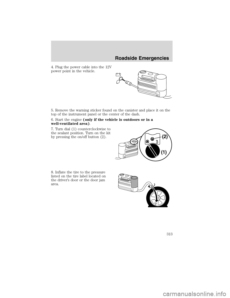
4. Plug the power cable into the 12V
power point in the vehicle.
5. Remove the warning sticker found on the canister and place it on the
top of the instrument panel or the center of the dash.
6. Start the engine(only if the vehicle is outdoors or in a
well-ventilated area).
7. Turn dial (1) counterclockwise to
the sealant position. Turn on the kit
by pressing the on/off button (2).
8. Inflate the tire to the pressure
listed on the tire label located on
the driver’s door or the door jam
area.
Roadside Emergencies
313
2010 Flex(471)
Owners Guide, 1st Printing
USA(fus)
Page 320 of 397
Preparing your vehicle
When the battery is disconnected or a new battery is installed, the
automatic transmission must relearn its shift strategy. As a result, the
transmission may have firm and/or soft shifts. This operation is
considered normal and will not affect function or durability of the
transmission. Over time, the adaptive learning process will fully update
transmission operation.
1.Use only a 12–volt supply to start your vehicle.
2. Do not disconnect the battery of the disabled vehicle as this could
damage the vehicle’s electrical system.
3. Park the booster vehicle close to the hood of the disabled vehicle
making sure the two vehiclesdo nottouch. Set the parking brake on
both vehicles and stay clear of the engine cooling fan and other moving
parts.
4. Check all battery terminals and remove any excessive corrosion before
you attach the battery cables. Ensure that vent caps are tight and level.
5. Turn the heater fan on in both vehicles to protect from any electrical
surges. Turn all other accessories off.
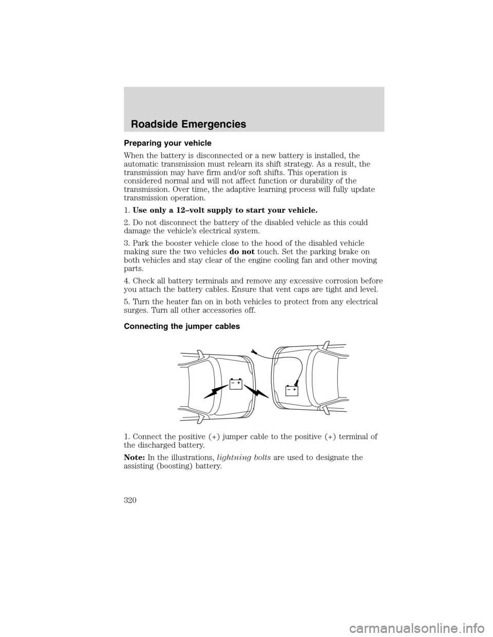
Connecting the jumper cables
1. Connect the positive (+) jumper cable to the positive (+) terminal of
the discharged battery.
Note:In the illustrations,lightning boltsare used to designate the
assisting (boosting) battery.
+–+–
Roadside Emergencies
320
2010 Flex(471)
Owners Guide, 1st Printing
USA(fus)
Page 322 of 397
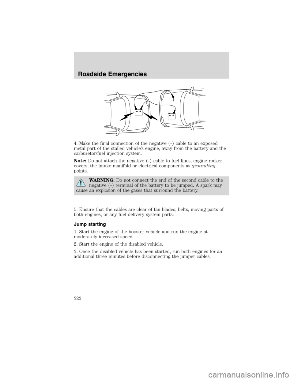
4. Make the final connection of the negative (-) cable to an exposed
metal part of the stalled vehicle’s engine, away from the battery and the
carburetor/fuel injection system.
Note:Do not attach the negative (-) cable to fuel lines, engine rocker
covers, the intake manifold or electrical components asgrounding
points.
WARNING:Do not connect the end of the second cable to the
negative (-) terminal of the battery to be jumped. A spark may
cause an explosion of the gases that surround the battery.
5. Ensure that the cables are clear of fan blades, belts, moving parts of
both engines, or any fuel delivery system parts.
Jump starting
1. Start the engine of the booster vehicle and run the engine at
moderately increased speed.
2. Start the engine of the disabled vehicle.
3. Once the disabled vehicle has been started, run both engines for an
additional three minutes before disconnecting the jumper cables.
+–+–
Roadside Emergencies
322
2010 Flex(471)
Owners Guide, 1st Printing
USA(fus)