display FORD FLEX 2019 Repair Manual
[x] Cancel search | Manufacturer: FORD, Model Year: 2019, Model line: FLEX, Model: FORD FLEX 2019Pages: 513, PDF Size: 39.3 MB
Page 202 of 513
STEERING
Electric Power Steering
WARNING: The electric power
steering system has diagnostic checks that
continuously monitor the system. If a fault
is detected, a message displays in the
information display. Stop your vehicle as
soon as it is safe to do so. Switch the
ignition off. After at least 10 seconds,
switch the ignition on and watch the
information display for a steering system
warning message. If a steering system
warning message returns, have the system
checked by an authorized dealer. WARNING: If the system detects an
error, you may not feel a difference in the
steering, however a serious condition may
exist. Obtain immediate service from an
authorized dealer, failure to do so may
result in loss of steering control.
Your vehicle has an electric power steering
system. There is no fluid reservoir. No
maintenance is required.
If your vehicle loses electrical power while
you are driving, electric power steering
assistance is lost. The steering system still
operates and you can steer your vehicle
manually. Manually steering your vehicle
requires more effort.
Extreme continuous steering may increase
the effort required for you to steer your
vehicle. This increased effort prevents
overheating and permanent damage to
the steering system. You do not lose the
ability to steer your vehicle manually.
Typical steering and driving maneuvers
allow the system to cool and return to
normal operation. Steering Tips
If the steering wanders or pulls, check for:
•
Correct tire pressures.
• Uneven tire wear.
• Loose or worn suspension
components.
• Loose or worn steering components.
• Improper vehicle alignment.
Note: A high crown in the road or high
crosswinds may also make the steering
seem to wander or pull.
Adaptive Learning
The electronic power steering system
adaptive learning helps correct road
irregularities and improves overall handling
and steering feel. It communicates with
the brake system to help operate
advanced stability control and accident
avoidance systems. Additionally, whenever
the battery is disconnected or a new
battery installed, you must drive your
vehicle a short distance before the system
relearns the strategy and reactivates all
systems.
COLLISION WARNING SYSTEM
(If Equipped)
PRINCIPLE OF OPERATION WARNING: This system is designed
to be a supplementary driving aid. It is not
intended to replace the driver ’s attention,
and judgment, or the need to apply the
brakes. This system does NOT activate the
brakes automatically. Failure to press the
brake pedal to activate the brakes may
result in a collision.
199
Flex (TP3) , enUSA, Edition date: 201803, Second-Printing Driving Aids
Page 203 of 513
WARNING: The collision warning
system with brake support cannot help
prevent all collisions. Do not rely on this
system to replace driver judgment and the
need to maintain distance and speed.
Note: The system does not detect, warn or
respond to potential collisions with vehicles
to the rear or sides of the vehicle.
Note: The collision warning system is active
at speeds above approximately
5 mph
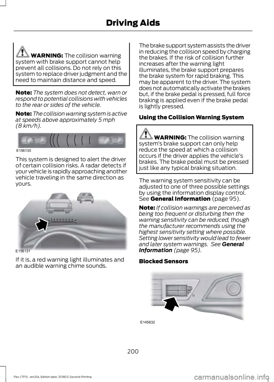
(8 km/h). This system is designed to alert the driver
of certain collision risks. A radar detects if
your vehicle is rapidly approaching another
vehicle traveling in the same direction as
yours.
If it is, a red warning light illuminates and
an audible warning chime sounds. The brake support system assists the driver
in reducing the collision speed by charging
the brakes. If the risk of collision further
increases after the warning light
illuminates, the brake support prepares
the brake system for rapid braking. This
may be apparent to the driver. The system
does not automatically activate the brakes
but, if the brake pedal is pressed, full force
braking is applied even if the brake pedal
is lightly pressed.
Using the Collision Warning System WARNING:
The collision warning
system ’s brake support can only help
reduce the speed at which a collision
occurs if the driver applies the vehicle ’s
brakes. The brake pedal must be pressed
just like any typical braking situation.
The warning system sensitivity can be
adjusted to one of three possible settings
by using the information display control.
See
General Information (page 95).
Note: If collision warnings are perceived as
being too frequent or disturbing then the
warning sensitivity can be reduced, though
the manufacturer recommends using the
highest sensitivity setting where possible.
Setting lower sensitivity would lead to fewer
and later system warnings. See
General
Information (page 95).
Blocked Sensors 200
Flex (TP3) , enUSA, Edition date: 201803, Second-Printing Driving AidsE156130 E156131 E145632
Page 204 of 513
If a message regarding a blocked sensor
appears in the information display, the
radar signals from the sensor have been
obstructed. The sensors are located behind
a fascia cover near the driver side of the
lower grille. When the sensors are
obstructed, a vehicle ahead cannot be
detected and the collision warning system
does not function. The following table lists
possible causes and actions for this
message being displayed. Action
Cause
Clean the grille surface in front of the radaror remove the object causing the obstruc- tion
The surface of the radar in the grille is dirty
or obstructed in some way
Wait a short time. It may take several
minutes for the radar to detect that it is no longer obstructed
The surface of the radar in the grille is clean
but the message remains in the display
The collision warning system is temporarily
disabled. Collision warning should automat-ically reactivate a short time after the weather conditions improve
Heavy rain, spray, snow, or fog is interfering
with the radar signals
The collision warning system is temporarily
disabled. Collision warning should automat-ically reactivate a short time after the weather conditions improve
Swirling water, or snow or ice on the surface
of the road may interfere with the radar signals
System Limitations WARNING: The collision warning
system ’s brake support can only help
reduce the speed at which a collision
occurs if the driver applies the vehicle ’s
brakes. The brake pedal must be pressed
just like any typical braking situation.
Due to the nature of radar technology,
there may be certain instances where
vehicles do not provide a collision warning.
These include:
• Stationary vehicles or vehicles moving
below 6 mph (10 km/h).
• Pedestrians or objects in the roadway.
• Oncoming vehicles in the same lane. •
Severe weather conditions (see
blocked sensor section).
• Debris build-up on the grille near the
headlamps (see blocked sensor
section).
• Small distance to vehicle ahead.
• Steering wheel and pedal movements
are large (very active driving style).
If the front end of the vehicle is hit or
damaged, the radar sensing zone may be
altered causing missed or false collision
warnings. See your authorized dealer to
have your collision warning radar checked
for proper coverage and operation.
201
Flex (TP3) , enUSA, Edition date: 201803, Second-Printing Driving Aids
Page 212 of 513
RV & Trailer Towing Guide Online
http://www.fleet.ford.com/towing-guides/
Website
TRAILER SWAY CONTROL (If
Equipped) WARNING:
Turning off trailer sway
control increases the risk of loss of vehicle
control, serious injury or death. Ford does
not recommend disabling this feature
except in situations where speed reduction
may be detrimental (such as hill climbing),
the driver has significant trailer towing
experience, and can control trailer sway
and maintain safe operation.
Note: This feature does not prevent trailer
sway, but reduces it when it begins.
Note: This feature cannot stop all trailers
from swaying.
Note: In some cases, if your vehicle speed
is too high, the system may turn on multiple
times, gradually reducing your vehicle speed.
The system applies the brakes to the
individual wheels and reduces engine
torque to aid vehicle stability. If the trailer
begins to sway, the stability control
warning lamp flashes and a message
appears in the information display. See
Information Messages
(page 103). Slow
your vehicle down, pull safely to the side
of the road and check for correct load
distribution. See
Load Carrying (page
202).
You can switch this feature off in the
information display. When you switch the
ignition on, the system automatically turns
on. RECOMMENDED TOWING
WEIGHTS
Note:
Do not exceed the trailer
weight for your vehicle
configuration listed in the chart
below.
Note: Make sure to take into
consideration trailer frontal area.
Do not exceed 20 ft² (1.86 m²) if
your vehicle can tow a class I
trailer, or 40 ft² (3.72 m²) if your
vehicle can tow a class III trailer.
Note: For high altitude operation,
reduce the gross combined weight
by 2% per
1,000 ft (300 m)
starting at the 1,000 ft (300 m)
elevation point.
Note: Certain states require
electric trailer brakes for trailers
over a specified weight. Check
state regulations for this specified
weight. The maximum trailer
weights listed may be limited to
this specified weight, as the
vehicle ’s electrical system may not
include the wiring connector
needed to use electric trailer
brakes.
209
Flex (TP3) , enUSA, Edition date: 201803, Second-Printing Towing
Page 242 of 513
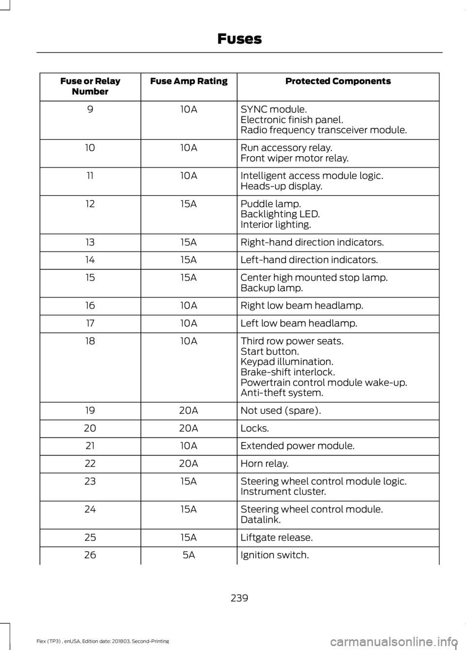
Protected Components
Fuse Amp Rating
Fuse or Relay
Number
SYNC module.
10A
9
Electronic finish panel.
Radio frequency transceiver module.
Run accessory relay.
10A
10
Front wiper motor relay.
Intelligent access module logic.
10A
11
Heads-up display.
Puddle lamp.
15A
12
Backlighting LED.
Interior lighting.
Right-hand direction indicators.
15A
13
Left-hand direction indicators.
15A
14
Center high mounted stop lamp.
15A
15
Backup lamp.
Right low beam headlamp.
10A
16
Left low beam headlamp.
10A
17
Third row power seats.
10A
18
Start button.
Keypad illumination.
Brake-shift interlock.
Powertrain control module wake-up.
Anti-theft system.
Not used (spare).
20A
19
Locks.
20A
20
Extended power module.
10A
21
Horn relay.
20A
22
Steering wheel control module logic.
15A
23
Instrument cluster.
Steering wheel control module.
15A
24
Datalink.
Liftgate release.
15A
25
Ignition switch.
5A
26
239
Flex (TP3) , enUSA, Edition date: 201803, Second-Printing Fuses
Page 243 of 513
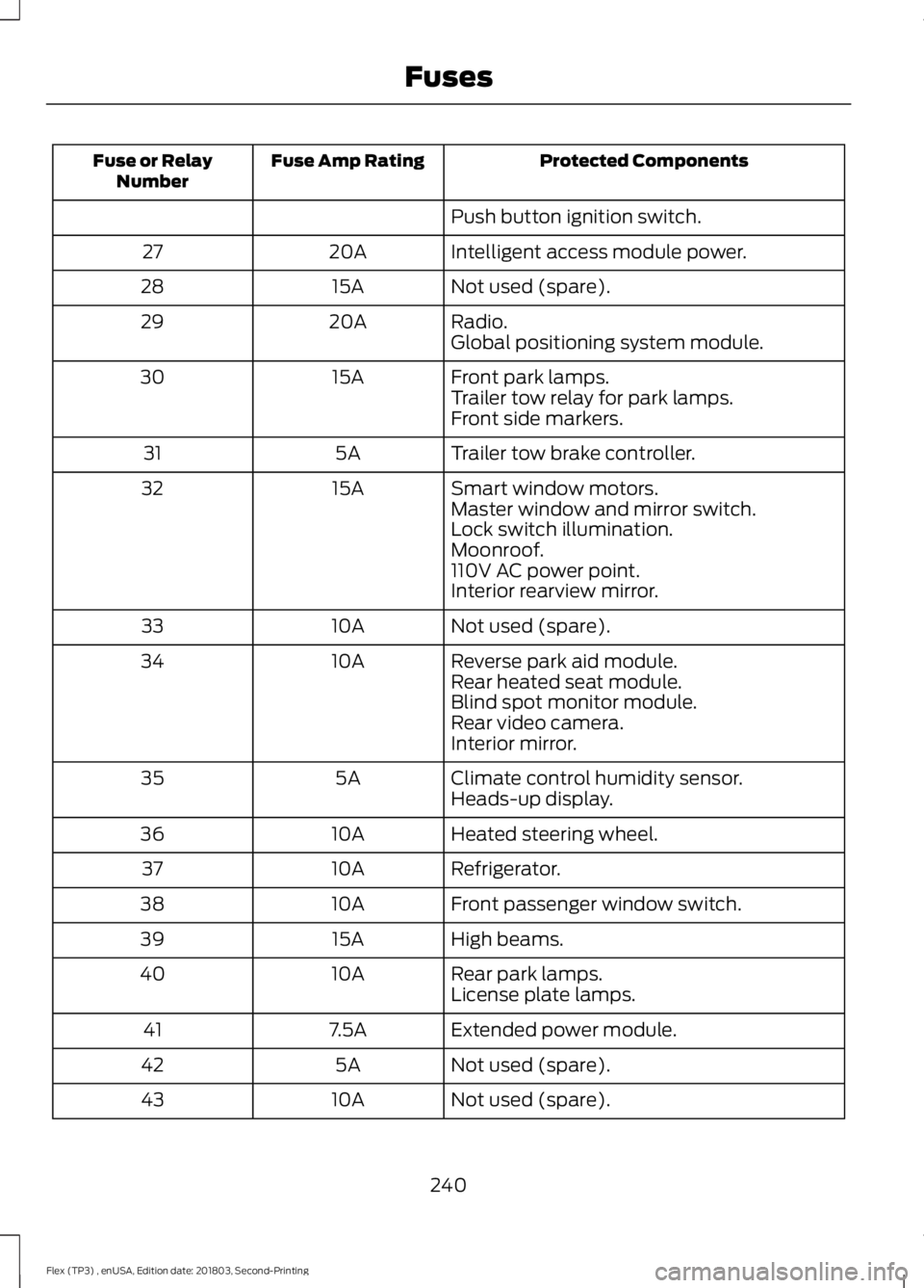
Protected Components
Fuse Amp Rating
Fuse or Relay
Number
Push button ignition switch.
Intelligent access module power.
20A
27
Not used (spare).
15A
28
Radio.
20A
29
Global positioning system module.
Front park lamps.
15A
30
Trailer tow relay for park lamps.
Front side markers.
Trailer tow brake controller.
5A
31
Smart window motors.
15A
32
Master window and mirror switch.
Lock switch illumination.
Moonroof.
110V AC power point.
Interior rearview mirror.
Not used (spare).
10A
33
Reverse park aid module.
10A
34
Rear heated seat module.
Blind spot monitor module.
Rear video camera.
Interior mirror.
Climate control humidity sensor.
5A
35
Heads-up display.
Heated steering wheel.
10A
36
Refrigerator.
10A
37
Front passenger window switch.
10A
38
High beams.
15A
39
Rear park lamps.
10A
40
License plate lamps.
Extended power module.
7.5A
41
Not used (spare).
5A
42
Not used (spare).
10A
43
240
Flex (TP3) , enUSA, Edition date: 201803, Second-Printing Fuses
Page 251 of 513
Only use oils certified for gasoline engines
by the American Petroleum Institute (API).
An oil with this trademark symbol
conforms to the current engine and
emission system protection standards and
fuel economy requirements of the
International Lubricants Specification
Advisory Committee (ILSAC).
To top up the engine oil level do the
following:
1. Clean the area surrounding the engine
oil filler cap before you remove it.
2. Remove the engine oil filler cap. See Under Hood Overview (page 244).
Turn it counterclockwise and remove
it.
3. Add engine oil that meets our specifications. See
Capacities and
Specifications (page 305). You may
have to use a funnel to pour the engine
oil into the opening.
4. Recheck the oil level.
5. If the oil level is correct, replace the dipstick and make sure it is fully seated.
6. Replace the engine oil filler cap. Turn it clockwise until you feel a strong
resistance.
Note: Do not add oil further than the
maximum mark. Oil levels above the
maximum mark may cause engine damage.
Note: Make sure you install the oil filler cap
correctly.
Note: Soak up any spillage with an
absorbent cloth immediately.
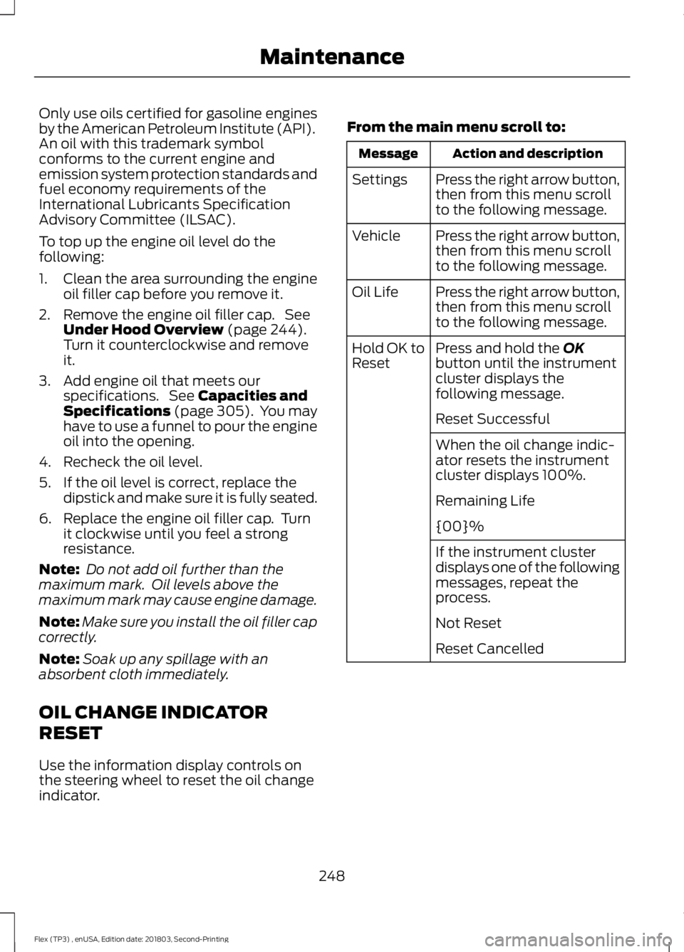
OIL CHANGE INDICATOR
RESET
Use the information display controls on
the steering wheel to reset the oil change
indicator. From the main menu scroll to: Action and description
Message
Press the right arrow button,
then from this menu scroll
to the following message.
Settings
Press the right arrow button,
then from this menu scroll
to the following message.
Vehicle
Press the right arrow button,
then from this menu scroll
to the following message.
Oil Life
Press and hold the
OK
button until the instrument
cluster displays the
following message.
Hold OK to
Reset
Reset Successful
When the oil change indic-
ator resets the instrument
cluster displays 100%.
Remaining Life
{00}%
If the instrument cluster
displays one of the following
messages, repeat the
process.
Not Reset
Reset Cancelled
248
Flex (TP3) , enUSA, Edition date: 201803, Second-Printing Maintenance
Page 254 of 513
Do not add extra inhibitors or additives to
the coolant. These can be harmful and
compromise the corrosion protection of
the coolant.
Recycled Coolant
We do not recommend the use of recycled
coolant as an approved recycling process
is not yet available.
Note:
Dispose of used coolant in the
appropriate manner.
Follow your community's regulations and
standards for recycling and disposing of
automotive fluids.
Severe Climates
If you drive in extremely cold climates:
• It may be necessary to increase the
coolant concentration above 50%.
• A coolant concentration of 60%
provides improved freeze point
protection. Coolant concentrations
above 60% decrease the overheat
protection characteristics of the
coolant and may cause engine
damage.
If you drive in extremely hot climates:
• You can decrease the coolant
concentration to 40%.
• Coolant concentrations below 40%
decrease the freeze and corrosion
protection characteristics of the
coolant and may cause engine
damage.
Vehicles driven year-round in non-extreme
climates should use prediluted coolant for
optimum cooling system and engine
protection. Coolant Change
At specific mileage intervals, as listed in
the scheduled maintenance information,
the coolant should be changed. Add
prediluted coolant approved to the correct
specification. See Capacities and
Specifications (page 299).
Fail-Safe Cooling
Fail-safe cooling allows you to temporarily
drive your vehicle before any incremental
component damage occurs. The fail-safe
distance depends on ambient
temperature, vehicle load and terrain.
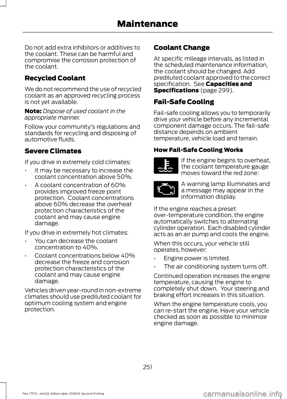
How Fail-Safe Cooling Works If the engine begins to overheat,
the coolant temperature gauge
moves toward the red zone:
A warning lamp illuminates and
a message may appear in the
information display.
If the engine reaches a preset
over-temperature condition, the engine
automatically switches to alternating
cylinder operation. Each disabled cylinder
acts as an air pump and cools the engine.
When this occurs, your vehicle still
operates, however:
• Engine power is limited.
• The air conditioning system turns off.
Continued operation increases the engine
temperature, causing the engine to
completely shut down. Your steering and
braking effort increases in this situation.
When the engine temperature cools, you
can re-start the engine. Have your vehicle
checked as soon as possible to minimize
engine damage.
251
Flex (TP3) , enUSA, Edition date: 201803, Second-Printing Maintenance
Page 255 of 513
When Fail-Safe Mode Is Activated
WARNING: Fail-safe mode is for use
during emergencies only. Operate your
vehicle in fail-safe mode only as long as
necessary to bring your vehicle to rest in a
safe location and seek immediate repairs.
When in fail-safe mode, your vehicle will
have limited power, will not be able to
maintain high-speed operation, and may
completely shut down without warning,
potentially losing engine power, power
steering assist, and power brake assist,
which may increase the possibility of a
crash resulting in serious injury. WARNING:
Do not remove the
coolant reservoir cap when the engine is
on or the cooling system is hot. Wait 10
minutes for the cooling system to cool
down. Cover the coolant reservoir cap with
a thick cloth to prevent the possibility of
scalding and slowly remove the cap.
Failure to follow this instruction could
result in personal injury.
Your vehicle has limited engine power
when in the fail-safe mode, drive your
vehicle with caution. Your vehicle does not
maintain high-speed operation and the
engine may operate poorly.
Remember that the engine is capable of
automatically shutting down to prevent
engine damage. In this situation:
1. Pull off the road as soon as safely possible and switch the engine off.
2. If you are a member of a roadside assistance program, we recommend
that you contact your roadside
assistance service provider.
3. If this is not possible, wait for a short period of time for the engine to cool. 4. Check the coolant level. If the coolant
level is at or below the minimum mark,
add prediluted coolant immediately.
5. When the engine temperature cools, you can re-start the engine. Have your
vehicle checked as soon as possible to
minimize engine damage.
Note: Driving your vehicle without repair
increases the chance of engine damage.
Engine Coolant Temperature
Management
(If Equipped) WARNING:
To reduce the risk of
crash and injury, be prepared that the
vehicle speed may reduce and the vehicle
may not be able to accelerate with full
power until the coolant temperature
reduces.
If you tow a trailer with your vehicle, the
engine may temporarily reach a higher
temperature during severe operating
conditions, for example ascending a long
or steep grade in high ambient
temperatures.
At this time, you may notice the coolant
temperature gauge moves toward the red
zone and a message may appear in the
information display.
You may notice a reduction in vehicle
speed caused by reduced engine power in
order to manage the engine coolant
temperature. Your vehicle may enter this
mode if certain high-temperature and
high-load conditions take place. The
amount of speed reduction depends on
vehicle loading, grade and ambient
temperature. If this occurs, there is no
need to stop your vehicle. You can
continue to drive.
252
Flex (TP3) , enUSA, Edition date: 201803, Second-Printing Maintenance
Page 256 of 513
The air conditioning may automatically
turn on and off during severe operating
conditions to protect the engine from
overheating. When the coolant
temperature decreases to the normal
operating temperature, the air conditioning
turns on.
If the coolant temperature gauge moves
fully into the red zone, or if the coolant
temperature warning or service engine
soon messages appear in your information
display, do the following:
1. Stop your vehicle as soon as it is safe
to do so. Fully apply the parking brake,
shift into park (P) or neutral (N).
2. Leave the engine running until the coolant temperature gauge needle
returns to the normal position. If the
temperature does not drop after
several minutes, follow the remaining
steps.
3. Switch the engine off and wait for it to
cool. Check the coolant level.
4. If the coolant level is at or below the minimum mark, add prediluted coolant
immediately.
5. If the coolant level is normal, restart the engine and continue.
AUTOMATIC TRANSMISSION
FLUID CHECK
Do not use supplemental transmission
fluid additives because they are
unnecessary and could lead to
transmission damage that may not be
covered by the vehicle Warranty.
The transmission does not consume fluid.
However, if the transmission slips or shifts
slowly you should check the fluid level. If
you notice a sign of leaking fluid, contact
an authorized dealer. Checking the Transmission Fluid
Level WARNING: The dipstick and
surrounding components are hot. Use
gloves when moving components and
checking the transmission fluid level.
Failure to follow this warning could result
in serious personal injury.
Only check the transmission fluid level
when the engine is at normal operating
temperature 179°F (82°C)-199°F (93°C).
Normal operating temperature is reached
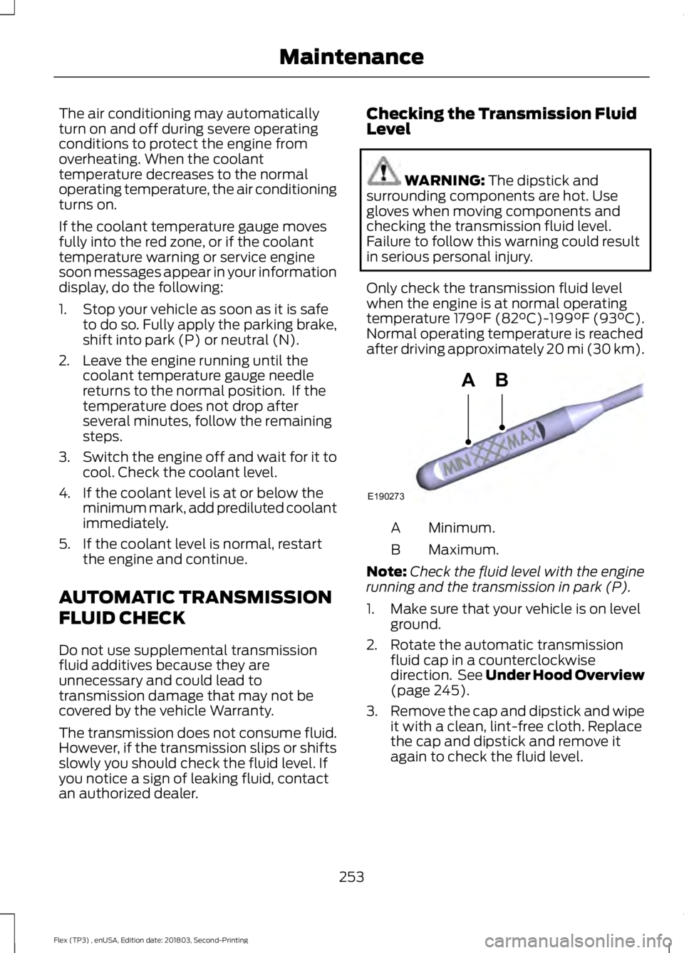
after driving approximately 20 mi (30 km). Minimum.
A
Maximum.
B
Note: Check the fluid level with the engine
running and the transmission in park (P).
1. Make sure that your vehicle is on level ground.
2. Rotate the automatic transmission fluid cap in a counterclockwise
direction. See
Under Hood Overview
(page 245).
3. Remove the cap and dipstick and wipe
it with a clean, lint-free cloth. Replace
the cap and dipstick and remove it
again to check the fluid level.
253
Flex (TP3) , enUSA, Edition date: 201803, Second-Printing MaintenanceE190273
AB