fuses FORD FLEX 2019 Owners Manual
[x] Cancel search | Manufacturer: FORD, Model Year: 2019, Model line: FLEX, Model: FORD FLEX 2019Pages: 513, PDF Size: 39.3 MB
Page 7 of 513
Roadside Emergencies
Roadside Assistance
..................................219
Hazard Flashers ..........................................
220
Fuel Shutoff ..................................................
220
Jump Starting the Vehicle .........................
221
Post-Crash Alert System ..........................
223
Transporting the Vehicle ..........................
223
Customer Assistance
Getting the Services You Need ..............
225
In California (U.S. Only) ............................
226
The Better Business Bureau (BBB) Auto Line Program (U.S. Only) .....................
227
Utilizing the Mediation/Arbitration Program (Canada Only) ......................
228
Getting Assistance Outside the U.S. and Canada .......................................................
228
Ordering Additional Owner's Literature ........................................................................\
230
Reporting Safety Defects (U.S. Only) ........................................................................\
230
Reporting Safety Defects (Canada Only) ........................................................................\
230
Fuses
Fuse Specification Chart ..........................
232
Changing a Fuse ...........................................
241
Maintenance
General Information ..................................
243
Opening and Closing the Hood .............
243
Under Hood Overview - 3.5L Duratec ........................................................................\
244
Under Hood Overview - 3.5L Ecoboost™ ........................................................................\
245
Engine Oil Dipstick ......................................
247
Engine Oil Check .........................................
247
Oil Change Indicator Reset .....................
248
Engine Coolant Check ..............................
249
Automatic Transmission Fluid Check ........................................................................\
253 Brake Fluid Check
.......................................
255
Power Steering Fluid Check ....................
255
Washer Fluid Check ...................................
255
Changing the 12V Battery ........................
256
Checking the Wiper Blades .....................
257
Changing the Wiper Blades ....................
258
Adjusting the Headlamps .......................
259
Removing a Headlamp ............................
260
Changing a Bulb .........................................
260
Changing the Engine Air Filter ...............
263
Vehicle Care
General Information ..................................
265
Cleaning Products ......................................
265
Cleaning the Exterior .................................
265
Waxing ............................................................
267
Cleaning the Engine ...................................
267
Cleaning the Windows and Wiper Blades ........................................................................\
267
Cleaning the Interior ..................................
268
Cleaning the Instrument Panel and Instrument Cluster Lens ......................
268
Cleaning Leather Seats ............................
269
Repairing Minor Paint Damage ..............
270
Cleaning the Wheels .................................
270
Vehicle Storage ............................................
270
Body Styling Kits ..........................................
272
Wheels and Tires
General Information ...................................
273
Tire Care .........................................................
275
Using Snow Chains ....................................
288
Tire Pressure Monitoring System .........
289
Changing a Road Wheel ..........................
293
Technical Specifications .........................
298
Capacities and Specifications
Engine Specifications - 3.5L Duratec ........................................................................\
299
4
Flex (TP3) , enUSA, Edition date: 201803, Second-Printing Table of Contents
Page 51 of 513
Passenger airbag
Passenger airbag status
indicator
Occupant
ON: Unlit Enabled
OFF: Unlit
Adult
ON: Lit
Note: When the passenger airbag status
indicator off light is illuminated, the
passenger (seat mounted) side airbag may
be disabled to avoid the risk of airbag
deployment injuries.
After all occupants have adjusted their
seats and put on seatbelts, it is very
important that they continue to sit
properly. A properly seated occupant sits
upright, leaning against the seatback, and
centered on the seat cushion, with their
feet comfortably extended on the floor.
Sitting improperly can increase the chance
of injury in a crash event. For example, if
an occupant slouches, lies down, turns
sideways, sits forward, leans forward or
sideways, or puts one or both feet up, the
chance of injury during a crash greatly
increases. Make sure the front passenger
sensing system is operating
properly. See Crash Sensors
and Airbag Indicator (page 50).
Do not attempt to repair or service the
system. Take your vehicle immediately to
an authorized dealer.
If it is necessary to modify an advanced
front airbag system to accommodate a
person with disabilities, contact the Ford
Customer Relationship Center. See
Getting the Services You Need
(page
225). SIDE AIRBAGS WARNING:
Do not place objects or
mount equipment on or near the airbag
cover, on the side of the seatbacks (of the
front seats), or in front seat areas that may
come into contact with a deploying airbag.
Failure to follow these instructions may
increase the risk of personal injury in the
event of a crash. WARNING:
Do not use accessory
seat covers. The use of accessory seat
covers may prevent the deployment of the
side airbags and increase the risk of injury
in an accident. WARNING:
Do not lean your head
on the door. The side airbag could injure
you as it deploys from the side of the
seatback. WARNING:
Do not attempt to
service, repair, or modify the airbag, its
fuses or the seat cover on a seat containing
an airbag as you could be seriously injured
or killed. Contact your authorized dealer
as soon as possible.
48
Flex (TP3) , enUSA, Edition date: 201803, Second-Printing Supplementary Restraints SystemE67017
Page 211 of 513
TOWING A TRAILER
WARNING: Do not exceed
the GVWR or the GAWR specified
on the certification label. WARNING:
Towing trailers
beyond the maximum
recommended gross trailer weight
exceeds the limit of your vehicle
and could result in engine
damage, transmission damage,
structural damage, loss of vehicle
control, vehicle rollover and
personal injury.
Note: Your vehicle may have
electrical items, such as fuses or
relays, related to towing. See
Fuses
(page 232).
Your vehicle's load capacity
designation is by weight, not by
volume, so you cannot necessarily
use all available space when
loading a vehicle or trailer.
Towing a trailer places an extra
load on your vehicle's engine,
transmission, axle, brakes, tires
and suspension. Inspect these
components periodically during,
and after, any towing operation. Load Placement
To help minimize how trailer
movement affects your vehicle
when driving:
•
Load the heaviest items closest
to the trailer floor.
• Load the heaviest items
centered between the left and
right side trailer tires.
• Load the heaviest items above
the trailer axles or just slightly
forward toward the trailer
tongue. Do not allow the final
trailer tongue weight to go
above or below 10-15% of the
loaded trailer weight.
• Select a ball mount with the
correct rise or drop. When both
the loaded vehicle and trailer
are connected, the trailer frame
should be level, or slightly
angled down toward your
vehicle, when viewed from the
side.
When driving with a trailer or
payload, a slight takeoff vibration
or shudder may be present due to
the increased payload weight.
Additional information regarding
proper trailer loading and setting
your vehicle up for towing is
located in the Load Carrying
chapter. See
Load Limit (page
202).
You can also find information in
the
RV & Trailer Towing Guide
available at your authorized
dealer, or online.
208
Flex (TP3) , enUSA, Edition date: 201803, Second-Printing Towing
Page 225 of 513
WARNING: Do not attach the end
of the positive cable to the studs or
L-shaped eyelet located above the positive
(+) terminal of your vehicle ’s battery. High
current may flow through and cause
damage to the fuses. WARNING:
Do not connect the end
of the second cable to the negative (-)
terminal of the battery to be jumped. A
spark may cause an explosion of the gases
that surround the battery.
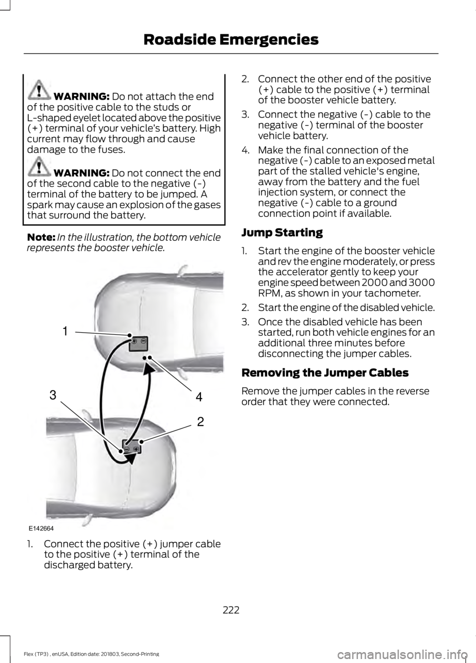
Note: In the illustration, the bottom vehicle
represents the booster vehicle. 1.
Connect the positive (+) jumper cable
to the positive (+) terminal of the
discharged battery. 2. Connect the other end of the positive
(+) cable to the positive (+) terminal
of the booster vehicle battery.
3. Connect the negative (-) cable to the negative (-) terminal of the booster
vehicle battery.
4. Make the final connection of the negative (-) cable to an exposed metal
part of the stalled vehicle's engine,
away from the battery and the fuel
injection system, or connect the
negative (-) cable to a ground
connection point if available.
Jump Starting
1. Start the engine of the booster vehicle
and rev the engine moderately, or press
the accelerator gently to keep your
engine speed between 2000 and 3000
RPM, as shown in your tachometer.
2. Start the engine of the disabled vehicle.
3. Once the disabled vehicle has been started, run both vehicle engines for an
additional three minutes before
disconnecting the jumper cables.
Removing the Jumper Cables
Remove the jumper cables in the reverse
order that they were connected.
222
Flex (TP3) , enUSA, Edition date: 201803, Second-Printing Roadside Emergencies4
2
1
3
E142664
Page 235 of 513
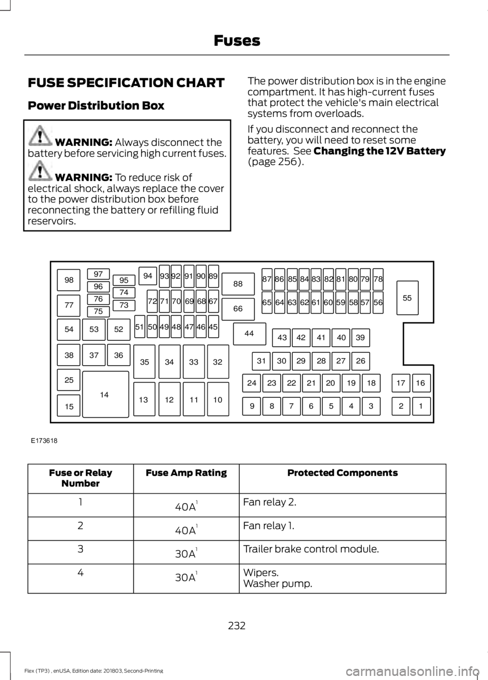
FUSE SPECIFICATION CHART
Power Distribution Box
WARNING: Always disconnect the
battery before servicing high current fuses. WARNING:
To reduce risk of
electrical shock, always replace the cover
to the power distribution box before
reconnecting the battery or refilling fluid
reservoirs. The power distribution box is in the engine
compartment. It has high-current fuses
that protect the vehicle's main electrical
systems from overloads.
If you disconnect and reconnect the
battery, you will need to reset some
features. See Changing the 12V Battery
(page
256). Protected Components
Fuse Amp Rating
Fuse or Relay
Number
Fan relay 2.
40A 1
1
Fan relay 1.
40A 1
2
Trailer brake control module.
30A 1
3
Wipers.
30A 1
4
Washer pump.
232
Flex (TP3) , enUSA, Edition date: 201803, Second-Printing FusesE173618
97
98
77 96
95
94
9392 919089
88
66
44 78
56
39 26 18 16
17
3 1
2
4
5
6
7
8
9 19
20
21
22
23
24 27
28
29
30
31 40
41
42
43 55
57
58
59
60
61
62
63
64
65 79
80
81
82
83
84
85
86
87
67
45
32
10
11
12
13 33
34
35 46
47
48
49
50
51 68
69
70
71
72
74
73
76
75
53
37 36
54
38
25
15
1452
Page 236 of 513
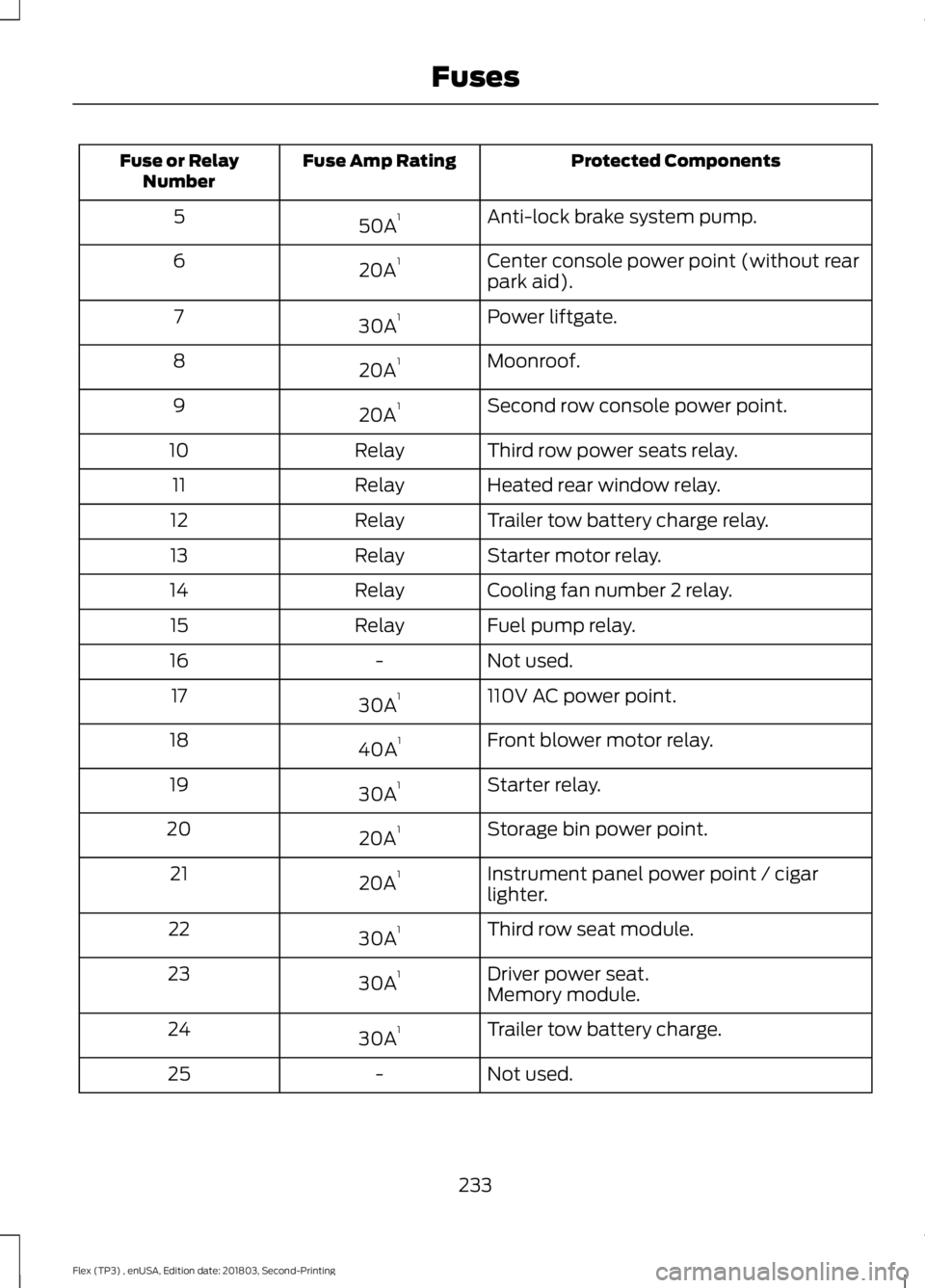
Protected Components
Fuse Amp Rating
Fuse or Relay
Number
Anti-lock brake system pump.
50A 1
5
Center console power point (without rear
park aid).
20A 1
6
Power liftgate.
30A 1
7
Moonroof.
20A 1
8
Second row console power point.
20A 1
9
Third row power seats relay.
Relay
10
Heated rear window relay.
Relay
11
Trailer tow battery charge relay.
Relay
12
Starter motor relay.
Relay
13
Cooling fan number 2 relay.
Relay
14
Fuel pump relay.
Relay
15
Not used.
-
16
110V AC power point.
30A 1
17
Front blower motor relay.
40A 1
18
Starter relay.
30A 1
19
Storage bin power point.
20A 1
20
Instrument panel power point / cigar
lighter.
20A 1
21
Third row seat module.
30A 1
22
Driver power seat.
30A 1
23
Memory module.
Trailer tow battery charge.
30A 1
24
Not used.
-
25
233
Flex (TP3) , enUSA, Edition date: 201803, Second-Printing Fuses
Page 237 of 513
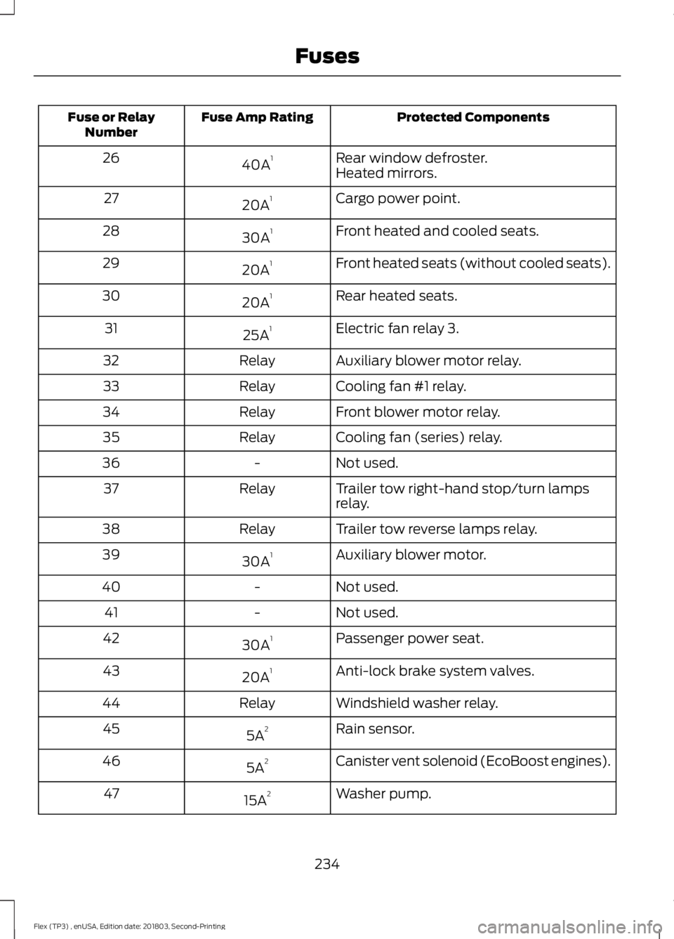
Protected Components
Fuse Amp Rating
Fuse or Relay
Number
Rear window defroster.
40A 1
26
Heated mirrors.
Cargo power point.
20A 1
27
Front heated and cooled seats.
30A 1
28
Front heated seats (without cooled seats).
20A 1
29
Rear heated seats.
20A 1
30
Electric fan relay 3.
25A 1
31
Auxiliary blower motor relay.
Relay
32
Cooling fan #1 relay.
Relay
33
Front blower motor relay.
Relay
34
Cooling fan (series) relay.
Relay
35
Not used.
-
36
Trailer tow right-hand stop/turn lamps
relay.
Relay
37
Trailer tow reverse lamps relay.
Relay
38
Auxiliary blower motor.
30A 1
39
Not used.
-
40
Not used.
-
41
Passenger power seat.
30A 1
42
Anti-lock brake system valves.
20A 1
43
Windshield washer relay.
Relay
44
Rain sensor.
5A 2
45
Canister vent solenoid (EcoBoost engines).
5A 2
46
Washer pump.
15A 2
47
234
Flex (TP3) , enUSA, Edition date: 201803, Second-Printing Fuses
Page 238 of 513

Protected Components
Fuse Amp Rating
Fuse or Relay
Number
Front park lamps.
10A 2
48
Not used.
-
49
Heated mirrors.
10A 2
50
Not used.
-
51
Not used.
-
52
Trailer tow left-hand stop/turn lamps relay.
Relay
53
Not used.
-
54
Wiper relay.
Relay
55
Fuel injectors.
30A 2
56
Fuel pump relay.
Left-hand high intensity discharge head-
lamp.
20A 2
57
Alternator sensor.
10A 2
58
Brake on/off switch.
10A 2
59
Trailer tow back-up lamps.
10A 2
60
Not used.
-
61
A/C clutch relay.
10A 2
62
Trailer tow stop/turn lamps.
15A 2
63
Rear wipers.
15A 2
64
Not used.
-
65
Powertrain control module – vehicle power
relay.
Relay
66
Vehicle power #2 – oxygen sensor heater.
20A 2
67
Mass airflow sensor.
Variable camshaft timing solenoid valve.
Canister vent solenoid.
Canister purge solenoid.
235
Flex (TP3) , enUSA, Edition date: 201803, Second-Printing Fuses
Page 239 of 513
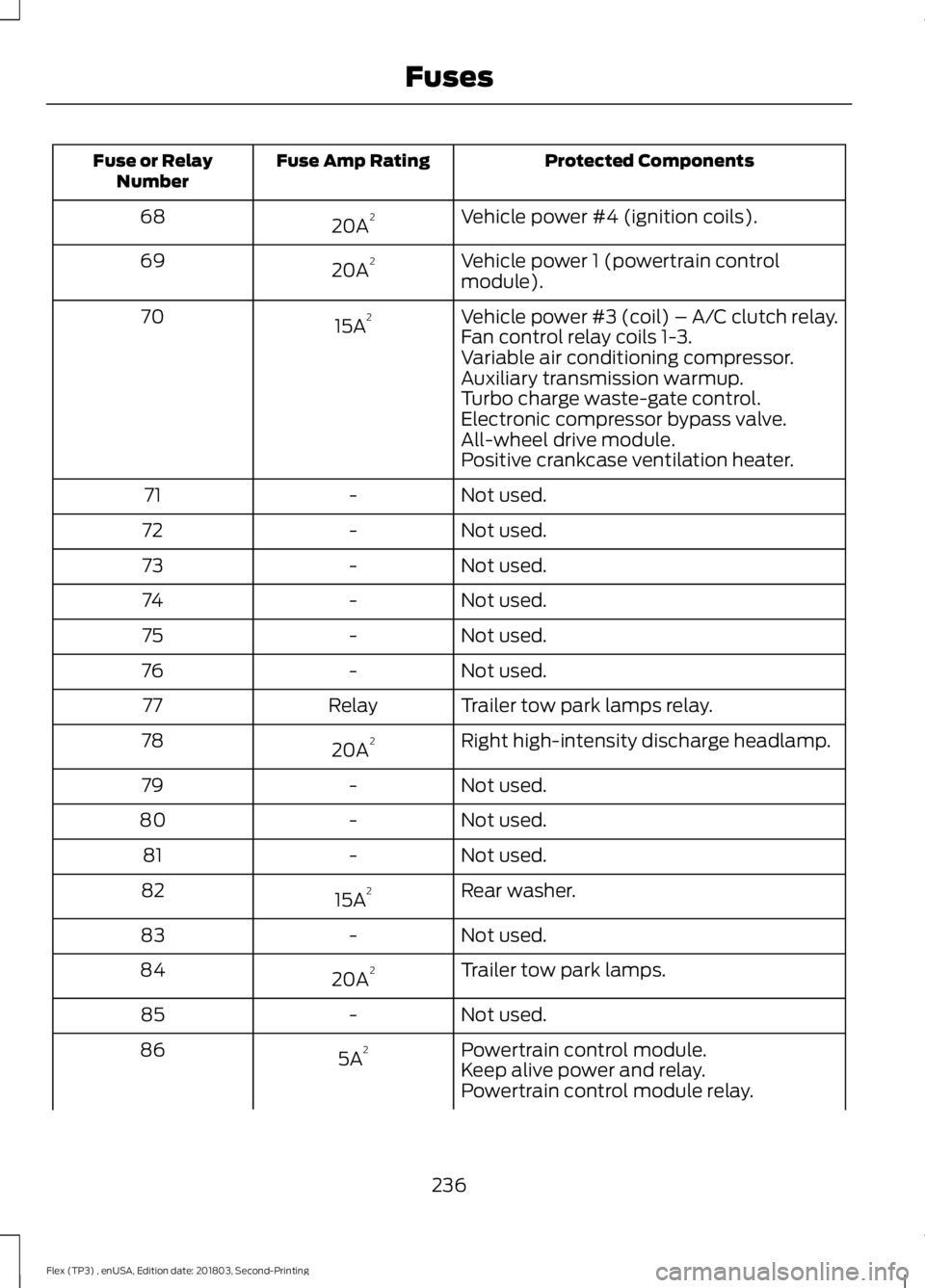
Protected Components
Fuse Amp Rating
Fuse or Relay
Number
Vehicle power #4 (ignition coils).
20A 2
68
Vehicle power 1 (powertrain control
module).
20A 2
69
Vehicle power #3 (coil) – A/C clutch relay.
15A 2
70
Fan control relay coils 1-3.
Variable air conditioning compressor.
Auxiliary transmission warmup.
Turbo charge waste-gate control.
Electronic compressor bypass valve.
All-wheel drive module.
Positive crankcase ventilation heater.
Not used.
-
71
Not used.
-
72
Not used.
-
73
Not used.
-
74
Not used.
-
75
Not used.
-
76
Trailer tow park lamps relay.
Relay
77
Right high-intensity discharge headlamp.
20A 2
78
Not used.
-
79
Not used.
-
80
Not used.
-
81
Rear washer.
15A 2
82
Not used.
-
83
Trailer tow park lamps.
20A 2
84
Not used.
-
85
Powertrain control module.
5A 2
86
Keep alive power and relay.
Powertrain control module relay.
236
Flex (TP3) , enUSA, Edition date: 201803, Second-Printing Fuses
Page 240 of 513
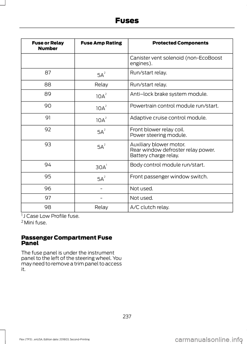
Protected Components
Fuse Amp Rating
Fuse or Relay
Number
Canister vent solenoid (non-EcoBoost
engines).
Run/start relay.
5A 2
87
Run/start relay.
Relay
88
Anti–lock brake system module.
10A 2
89
Powertrain control module run/start.
10A 2
90
Adaptive cruise control module.
10A 2
91
Front blower relay coil.
5A 2
92
Power steering module.
Auxiliary blower motor.
5A 2
93
Rear window defroster relay power.
Battery charge relay.
Body control module run/start.
30A 1
94
Front passenger window switch.
5A 2
95
Not used.
-
96
Not used.
-
97
A/C clutch relay.
Relay
98
1 J Case Low Profile fuse.
2 Mini fuse.
Passenger Compartment Fuse
Panel
The fuse panel is under the instrument
panel to the left of the steering wheel. You
may need to remove a trim panel to access
it.
237
Flex (TP3) , enUSA, Edition date: 201803, Second-Printing Fuses