washer FORD GRANADA 1985 Service Owner's Manual
[x] Cancel search | Manufacturer: FORD, Model Year: 1985, Model line: GRANADA, Model: FORD GRANADA 1985Pages: 255, PDF Size: 14.98 MB
Page 45 of 255
2B•2DOHCengine
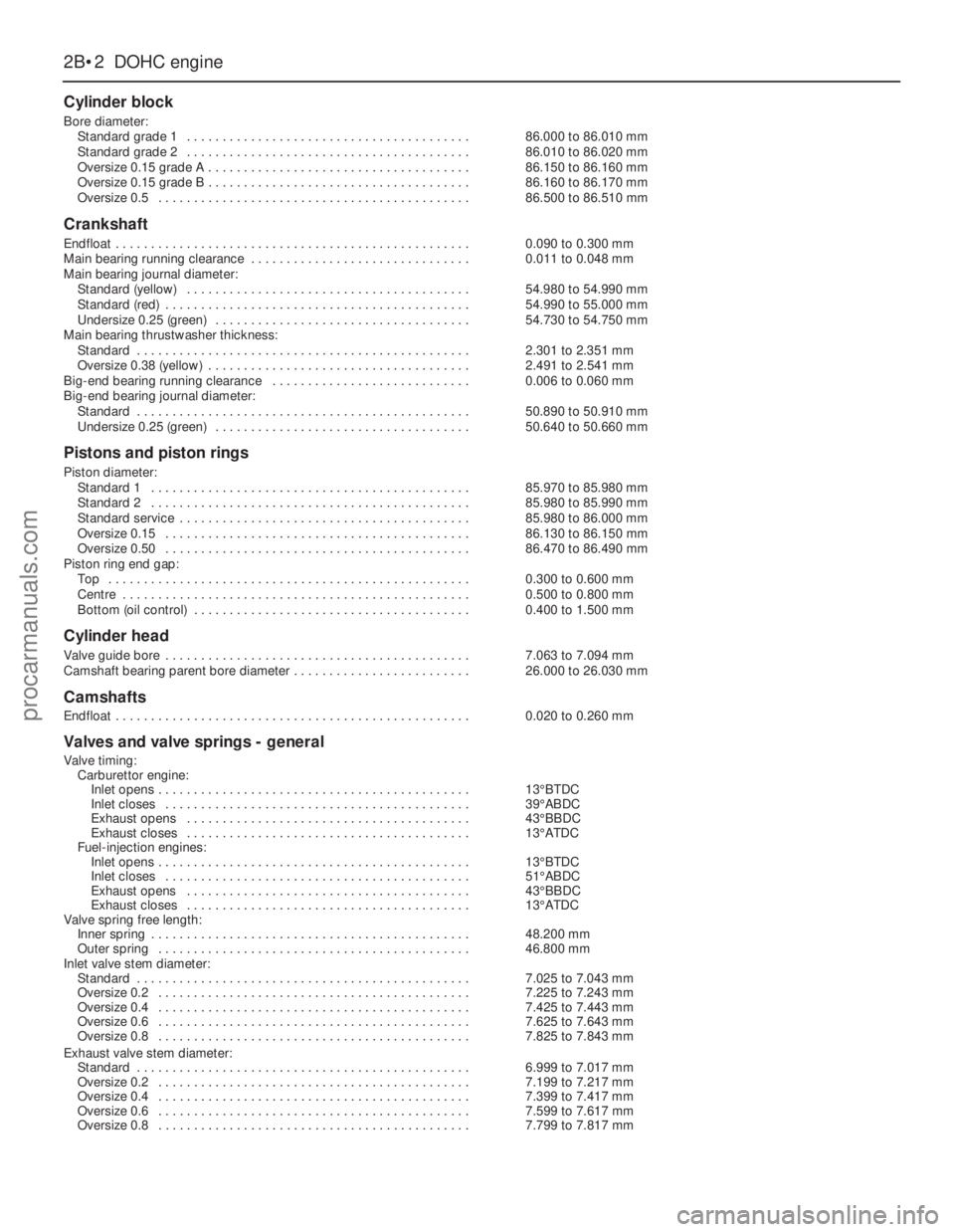
Cylinder block
Bore diameter:
Standard grade 1 . . . . . . . . . . . . . . . . . . . . . . . . . . . . . . . . . . . . . . . .86.000 to 86.010 mm
Standard grade 2 . . . . . . . . . . . . . . . . . . . . . . . . . . . . . . . . . . . . . . . .86.010 to 86.020 mm
Oversize 0.15 grade A . . . . . . . . . . . . . . . . . . . . . . . . . . . . . . . . . . . . .86.150 to 86.160 mm
Oversize 0.15 grade B . . . . . . . . . . . . . . . . . . . . . . . . . . . . . . . . . . . . .86.160 to 86.170 mm
Oversize 0.5 . . . . . . . . . . . . . . . . . . . . . . . . . . . . . . . . . . . . . . . . . . . .86.500 to 86.510 mm
Crankshaft
Endfloat . . . . . . . . . . . . . . . . . . . . . . . . . . . . . . . . . . . . . . . . . . . . . . . . . .0.090 to 0.300 mm
Main bearing running clearance . . . . . . . . . . . . . . . . . . . . . . . . . . . . . . .0.011 to 0.048 mm
Main bearing journal diameter:
Standard (yellow) . . . . . . . . . . . . . . . . . . . . . . . . . . . . . . . . . . . . . . . .54.980 to 54.990 mm
Standard (red) . . . . . . . . . . . . . . . . . . . . . . . . . . . . . . . . . . . . . . . . . . .54.990 to 55.000 mm
Undersize 0.25 (green) . . . . . . . . . . . . . . . . . . . . . . . . . . . . . . . . . . . .54.730 to 54.750 mm
Main bearing thrustwasher thickness:
Standard . . . . . . . . . . . . . . . . . . . . . . . . . . . . . . . . . . . . . . . . . . . . . . .2.301 to 2.351 mm
Oversize 0.38 (yellow) . . . . . . . . . . . . . . . . . . . . . . . . . . . . . . . . . . . . .2.491 to 2.541 mm
Big-end bearing running clearance . . . . . . . . . . . . . . . . . . . . . . . . . . . .0.006 to 0.060 mm
Big-end bearing journal diameter:
Standard . . . . . . . . . . . . . . . . . . . . . . . . . . . . . . . . . . . . . . . . . . . . . . .50.890 to 50.910 mm
Undersize 0.25 (green) . . . . . . . . . . . . . . . . . . . . . . . . . . . . . . . . . . . .50.640 to 50.660 mm
Pistons and piston rings
Piston diameter:
Standard 1 . . . . . . . . . . . . . . . . . . . . . . . . . . . . . . . . . . . . . . . . . . . . .85.970 to 85.980 mm
Standard 2 . . . . . . . . . . . . . . . . . . . . . . . . . . . . . . . . . . . . . . . . . . . . .85.980 to 85.990 mm
Standard service . . . . . . . . . . . . . . . . . . . . . . . . . . . . . . . . . . . . . . . . .85.980 to 86.000 mm
Oversize 0.15 . . . . . . . . . . . . . . . . . . . . . . . . . . . . . . . . . . . . . . . . . . .86.130 to 86.150 mm
Oversize 0.50 . . . . . . . . . . . . . . . . . . . . . . . . . . . . . . . . . . . . . . . . . . .86.470 to 86.490 mm
Piston ring end gap:
Top . . . . . . . . . . . . . . . . . . . . . . . . . . . . . . . . . . . . . . . . . . . . . . . . . . .0.300 to 0.600 mm
Centre . . . . . . . . . . . . . . . . . . . . . . . . . . . . . . . . . . . . . . . . . . . . . . . . .0.500 to 0.800 mm
Bottom (oil control) . . . . . . . . . . . . . . . . . . . . . . . . . . . . . . . . . . . . . . .0.400 to 1.500 mm
Cylinder head
Valve guide bore . . . . . . . . . . . . . . . . . . . . . . . . . . . . . . . . . . . . . . . . . . .7.063 to 7.094 mm
Camshaft bearing parent bore diameter . . . . . . . . . . . . . . . . . . . . . . . . .26.000 to 26.030 mm
Camshafts
Endfloat . . . . . . . . . . . . . . . . . . . . . . . . . . . . . . . . . . . . . . . . . . . . . . . . . .0.020 to 0.260 mm
Valves and valve springs - general
Valve timing:
Carburettor engine:
Inlet opens . . . . . . . . . . . . . . . . . . . . . . . . . . . . . . . . . . . . . . . . . . . .13°BTDC
Inlet closes . . . . . . . . . . . . . . . . . . . . . . . . . . . . . . . . . . . . . . . . . . .39°ABDC
Exhaust opens . . . . . . . . . . . . . . . . . . . . . . . . . . . . . . . . . . . . . . . .43°BBDC
Exhaust closes . . . . . . . . . . . . . . . . . . . . . . . . . . . . . . . . . . . . . . . .13°ATDC
Fuel-injection engines:
Inlet opens . . . . . . . . . . . . . . . . . . . . . . . . . . . . . . . . . . . . . . . . . . . .13°BTDC
Inlet closes . . . . . . . . . . . . . . . . . . . . . . . . . . . . . . . . . . . . . . . . . . .51°ABDC
Exhaust opens . . . . . . . . . . . . . . . . . . . . . . . . . . . . . . . . . . . . . . . .43°BBDC
Exhaust closes . . . . . . . . . . . . . . . . . . . . . . . . . . . . . . . . . . . . . . . .13°ATDC
Valve spring free length:
Inner spring . . . . . . . . . . . . . . . . . . . . . . . . . . . . . . . . . . . . . . . . . . . . .48.200 mm
Outer spring . . . . . . . . . . . . . . . . . . . . . . . . . . . . . . . . . . . . . . . . . . . .46.800 mm
Inlet valve stem diameter:
Standard . . . . . . . . . . . . . . . . . . . . . . . . . . . . . . . . . . . . . . . . . . . . . . .7.025 to 7.043 mm
Oversize 0.2 . . . . . . . . . . . . . . . . . . . . . . . . . . . . . . . . . . . . . . . . . . . .7.225 to 7.243 mm
Oversize 0.4 . . . . . . . . . . . . . . . . . . . . . . . . . . . . . . . . . . . . . . . . . . . .7.425 to 7.443 mm
Oversize 0.6 . . . . . . . . . . . . . . . . . . . . . . . . . . . . . . . . . . . . . . . . . . . .7.625 to 7.643 mm
Oversize 0.8 . . . . . . . . . . . . . . . . . . . . . . . . . . . . . . . . . . . . . . . . . . . .7.825 to 7.843 mm
Exhaust valve stem diameter:
Standard . . . . . . . . . . . . . . . . . . . . . . . . . . . . . . . . . . . . . . . . . . . . . . .6.999 to 7.017 mm
Oversize 0.2 . . . . . . . . . . . . . . . . . . . . . . . . . . . . . . . . . . . . . . . . . . . .7.199 to 7.217 mm
Oversize 0.4 . . . . . . . . . . . . . . . . . . . . . . . . . . . . . . . . . . . . . . . . . . . .7.399 to 7.417 mm
Oversize 0.6 . . . . . . . . . . . . . . . . . . . . . . . . . . . . . . . . . . . . . . . . . . . .7.599 to 7.617 mm
Oversize 0.8 . . . . . . . . . . . . . . . . . . . . . . . . . . . . . . . . . . . . . . . . . . . .7.799 to 7.817 mm
procarmanuals.com
Page 46 of 255
DOHCengine 2B•3
2B
Torque wrench settingsNmlbf ft
Main bearing cap bolts . . . . . . . . . . . . . . . . . . . . . . . . . . . . . . . . . . . . . .90 to 10466 to 77
Big-end bearing cap bolts:
Stage 1 . . . . . . . . . . . . . . . . . . . . . . . . . . . . . . . . . . . . . . . . . . . . . . . .6 to 84 to 6
Stage 2 . . . . . . . . . . . . . . . . . . . . . . . . . . . . . . . . . . . . . . . . . . . . . . . .15 to 1711 to 13
Stage 3 . . . . . . . . . . . . . . . . . . . . . . . . . . . . . . . . . . . . . . . . . . . . . . . .Tighten further 85°to 95°Tighten further 85°to 95°
Crankshaft pulley bolt:
Stage 1 . . . . . . . . . . . . . . . . . . . . . . . . . . . . . . . . . . . . . . . . . . . . . . . .45 to 5833 to 43
Stage 2 . . . . . . . . . . . . . . . . . . . . . . . . . . . . . . . . . . . . . . . . . . . . . . . .Tighten further 80°to 90°Tighten further 80°to 90°
Camshaft sprocket bolts . . . . . . . . . . . . . . . . . . . . . . . . . . . . . . . . . . . .55 to 6341 to 46
Flywheel bolts . . . . . . . . . . . . . . . . . . . . . . . . . . . . . . . . . . . . . . . . . . . . .82 to 9261 to 68
Oil pump bolts . . . . . . . . . . . . . . . . . . . . . . . . . . . . . . . . . . . . . . . . . . . .9 to 127 to 9
Oil pump sprocket bolt . . . . . . . . . . . . . . . . . . . . . . . . . . . . . . . . . . . . . .16 to 1912 to 14
Oil pump chain tensioner bolt . . . . . . . . . . . . . . . . . . . . . . . . . . . . . . . . .10 to 137 to 10
Sump bolts and nuts . . . . . . . . . . . . . . . . . . . . . . . . . . . . . . . . . . . . . . . .8 to 106 to 7
Sump studs . . . . . . . . . . . . . . . . . . . . . . . . . . . . . . . . . . . . . . . . . . . . . . .6 to 84 to 6
Sump drain plug . . . . . . . . . . . . . . . . . . . . . . . . . . . . . . . . . . . . . . . . . . .21 to 2815 to 21
Sump front mounting plate . . . . . . . . . . . . . . . . . . . . . . . . . . . . . . . . . . .23 to 2817 to 21
Oil baffle nuts . . . . . . . . . . . . . . . . . . . . . . . . . . . . . . . . . . . . . . . . . . . . .17 to 2113 to 15
Oil pick-up pipe-to-cylinder block bolts . . . . . . . . . . . . . . . . . . . . . . . . .9 to 137 to 10
Oil pressure warning lamp switch . . . . . . . . . . . . . . . . . . . . . . . . . . . . . .18 to 2213 to 16
Cylinder head bolts:
M11 bolts:
Stage 1 . . . . . . . . . . . . . . . . . . . . . . . . . . . . . . . . . . . . . . . . . . . . . .2518
Stage 2 . . . . . . . . . . . . . . . . . . . . . . . . . . . . . . . . . . . . . . . . . . . . . .5541
Stage 3 . . . . . . . . . . . . . . . . . . . . . . . . . . . . . . . . . . . . . . . . . . . . . .Tighten further 90°Tighten further 90°
Stage 4 . . . . . . . . . . . . . . . . . . . . . . . . . . . . . . . . . . . . . . . . . . . . . .Tighten further 90°Tighten further 90°
M8 bolts . . . . . . . . . . . . . . . . . . . . . . . . . . . . . . . . . . . . . . . . . . . . . . .36 to 3927 to 29
Camshaft cover bolts . . . . . . . . . . . . . . . . . . . . . . . . . . . . . . . . . . . . . . .6 to 84 to 6
Camshaft bearing cap nuts . . . . . . . . . . . . . . . . . . . . . . . . . . . . . . . . . .22 to 2616 to 19
Lower timing chain guide:
Upper bolt . . . . . . . . . . . . . . . . . . . . . . . . . . . . . . . . . . . . . . . . . . . . . .10 to 137 to 10
Lower bolt . . . . . . . . . . . . . . . . . . . . . . . . . . . . . . . . . . . . . . . . . . . . . .24 to 2818 to 21
Upper and lower timing chain cover bolts . . . . . . . . . . . . . . . . . . . . . . .7 to 105 to 7
Crankshaft rear oil seal housing bolts . . . . . . . . . . . . . . . . . . . . . . . . . .8 to 116 to 8
Engine-to-gearbox/transmission bolts . . . . . . . . . . . . . . . . . . . . . . . . . .29 to 4121 to 30
The 2.0 litre DOHC (Double OverHead
Camshaft) engine was introduced in June
1989 to replace the 2.0 litre SOHC engine
used previously in the Granada range, at the
same time a 2.0 litre version of the Scorpio
model was also introduced. The engine is of
four-cylinder, in-line type.
The crankshaft incorporates five main
bearings. Thrustwashers are fitted to the
centre main bearing in order to control
crankshaft endfloat.
The camshafts are driven by a chain from
the crankshaft and operate the angled valves
via hydraulic cam followers. One camshaft
operates the inlet valves, and the other
operates the exhaust valves.
The distributor is driven directly from the
front of the inlet camshaft, and the oil pump is
driven by a chain from the crankshaft. An
electric fuel pump is mounted in the fuel tank.
Lubrication is by means of a bi-rotor pump
which draws oil through a strainer located
inside the sump, and forces it through a full-
flow filter into the engine oil galleries, from
where it is distributed to the crankshaft and
camshafts. The big-end bearings are supplied
with oil via internal drillings in the crankshaft.
The undersides of the pistons are suppliedwith oil from drillings in the connecting rods.
The hydraulic cam followers are supplied with
oil from passages in the cylinder head. The
camshafts are lubricated by oil from spray
tubes mounted above the camshaft bearing
caps.
A closed crankcase ventilation system is
employed, whereby piston blow-by gases are
drawn from the crankcase, through a breather
pipe into the inlet manifold where they are
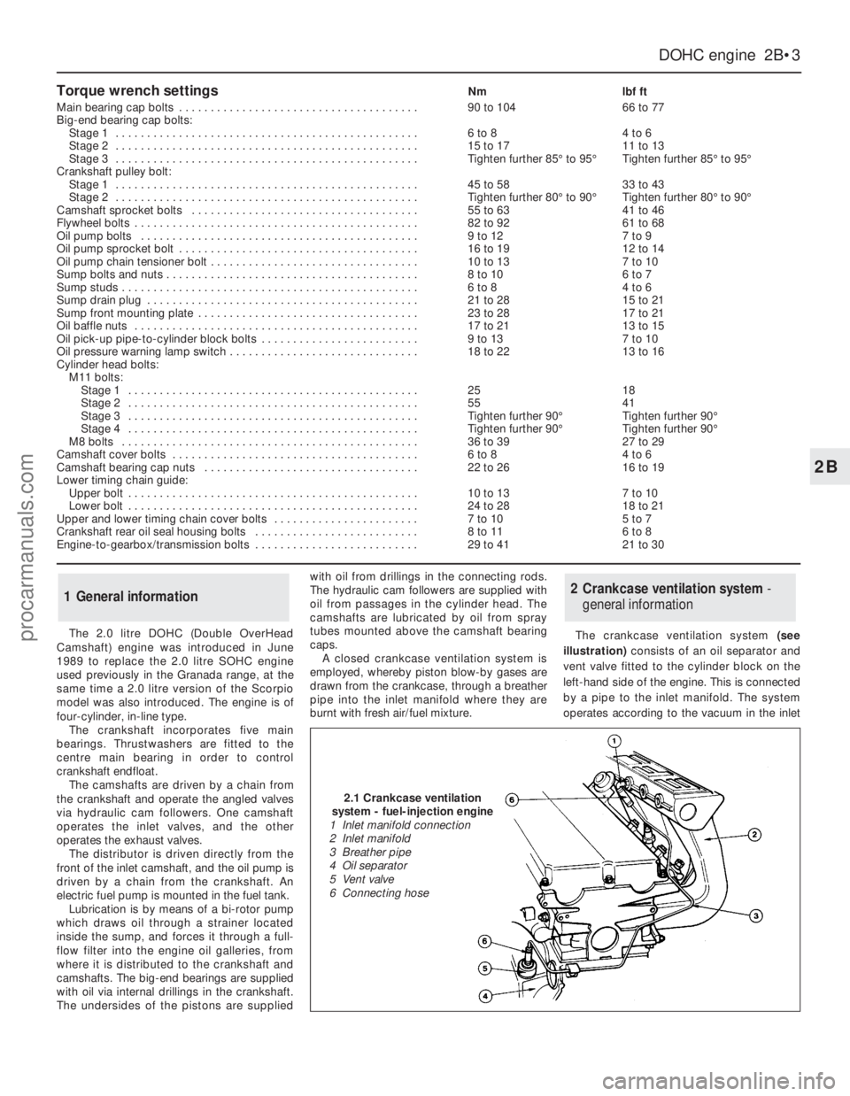
burnt with fresh air/fuel mixture.The crankcase ventilation system (see
illustration)consists of an oil separator and
vent valve fitted to the cylinder block on the
left-hand side of the engine. This is connected
by a pipe to the inlet manifold. The system
operates according to the vacuum in the inlet
2Crankcase ventilation system -
general information1General information
2.1 Crankcase ventilation
system - fuel-injection engine
1 Inlet manifold connection
2 Inlet manifold
3 Breather pipe
4 Oil separator
5 Vent valve
6 Connecting hose
procarmanuals.com
Page 49 of 255
Note: Refer to Part A, Section 4 of this Chapter
and to the warning that appears at the start of
Section 5 before proceeding. A hoist and lifting
tackle will be required for this operation.
1Proceed as described in paragraphs 1 to 21
of Section 5.
2Unscrew the securing bolt, and disconnect
the earth lead from the rear left-hand side of
the cylinder head.
3Unscrew the nuts securing the engine
mountings to the engine mounting brackets.
4Jack up the vehicle and support it securely
on axle stands (see “Jacking”). Ensure that
there is enough working room beneath the
vehicle.
5To improve access, disconnect the exhaust
downpipe from the manifold and remove the
exhaust system.
6Drain the engine oil into a suitable container.
7On models fitted with a catalytic converter,
release the securing clips and withdraw the
exhaust heat shield from under the vehicle for
access to the propeller shaft.
8Remove the propeller shaft.
9Where applicable, bend back the locktabs,
then unscrew the two bolts in each case
securing the two anti-roll bar mounting clamps
to the vehicle underbody. Lower the anti-roll
bar as far as possible.
10Proceed as described in paragraphs 30
and 31 of Section 5.
11Support the gearbox with a trolley jack,
using a block of wood between the jack and
the gearbox to spread the load.
12Unscrew the four nuts securing the
gearbox crossmember to the vehicle
underbody. Unscrew the central bolt securing
the crossmember to the gearbox, and remove
the crossmember. Note the position of the
earth strap, where applicable. Recover the
mounting cup, and the exhaust mounting
bracket and heat shield (as applicable).
13Lower the gearbox slightly on the jack,
then remove the circlip, and disconnect the
speedometer drive cable from the gearbox.
14Disconnect the wiring from the reversing
lamp switch, and on models with fuel-injection,
disconnect the wiring from the vehicle speed
sensor mounted in the side of the gearbox.
15Slacken and remove the two bolts and
washers (one either side) securing the gear
linkage support bracket to the gearbox.
16Using a pin punch, drive out the roll pin
securing the gearchange rod to the gear linkage.
17Attach a hoist to the engine lifting brackets
located at the front and rear of the cylinder head,
and slowly take the weight of the engine. Arrange
the lifting tackle so that the engine/gearbox
assembly will assume a steep angle of
approximately 40°to 45°as it is being removed.
18To improve clearance in the engine
compartment when lifting the engine, unboltthe engine mounting brackets from the
cylinder block, and remove them.
19Ensure that the steering wheel is positioned
in the straight-ahead position then, using a dab
of paint or a marker pen, make alignment marks
between the intermediate shaft lower clamp
and steering gear pinion. Slacken and remove
the lower clamp bolt then disconnect the
intermediate shaft from the steering gear.
20Detach the brake lines from the front
suspension crossmember.
21Support the crossmember with a jack (do not
remove the jack from under the gearbox), then
loosen the bolts securing the crossmember to the
underbody. Remove the crossmember securing
bolts, and carefully lower the crossmember to
allow sufficient room for the engine sump to clear
the steering rack and crossmember as the
engine/gearbox assembly is removed.
22Make a final check to ensure that all
relevant wires, pipes and hoses have been
disconnected to facilitate removal of the
engine/gearbox assembly.
23Raise the engine/gearbox, at the same
time lowering the trolley jack which is
supporting the gearbox.
24Place a suitable rod across the vehicle
underbody to support the gear linkage support
bracket whilst the gearbox is removed.
25Tilt the engine/gearbox assembly using
the hoist and the trolley jack, until the
assembly can be lifted from the vehicle. Take
care not to damage surrounding components.
26If the vehicle is to be moved, with the
engine/gearbox assembly removed, temporarily
refit the suspension crossmember and the anti-
roll bar to the underbody, and reconnect the
steering column to the intermediate shaft.
27To separate the engine from the gearbox,
proceed as follows.
28Remove the starter motor.
29Support the engine and gearbox
horizontally on blocks of wood.
30Unscrew the engine-to-gearbox bolts,
noting the locations of the bolts, and the
positions of the earth strap and any wiring clips
attached to the bolts. Recover any shims fitted
between the sump and the gearbox when
removing the lower engine-to-gearbox bolts.
31Unscrew the bolt from the engine adapter
plate.
32Pull the engine and gearbox apart, taking
care not to strain the gearbox input shaft. It
may be necessary to rock the units slightly to
separate them.
Note: Refer to Part A, Section 4 of this
Chapter and to the warning that appears at the
start of Section 5 before proceeding. A
suitable hoist and lifting tackle will be required
for this operation. Any suspected faults in the
automatic transmission should be referred to a
Ford dealer or automatic transmissionspecialist before removal of unit, as the
specialist fault diagnosis equipment is
designed to operate with the transmission in
the vehicle.
1Proceed as described in paragraphs 1 to 21
of Section 5.
2Unscrew the securing bolt, and disconnect
the earth lead from the rear left-hand side of
the cylinder head.
3Unscrew the nuts securing the engine
mountings to the engine mounting brackets.
4Jack up the vehicle and support it securely
on axle stands (see “Jacking”). Ensure that
there is enough working room beneath the
vehicle.
5To improve access, disconnect the exhaust
downpipe from the manifold and remove the
exhaust system .
6Drain the engine oil into a suitable container.
7On models fitted with a catalytic converter,
release the securing clips and withdraw the
exhaust heat shield from under the vehicle for
access to the propeller shaft.
8Remove the propeller shaft.
9Where applicable, bend back the locktabs,
then unscrew the two bolts in each case
securing the two anti-roll bar mounting clamps
to the vehicle underbody. Lower the anti-roll
bar as far as possible.
10Support the transmission with a trolley
jack, using a block of wood between the jack
and the transmission to spread the load.
11Unscrew the four bolts securing the
transmission crossmember to the vehicle
underbody. Unscrew the central bolt securing
the crossmember to the transmission, and
remove the crossmember. Note the position of
the earth strap, where applicable. Recover the
mounting cup, and the exhaust mounting
bracket and heat shield (as applicable).
12Lower the transmission slightly on the jack.
13Unscrew the unions and disconnect the
fluid cooler pipes from the transmission. Plug
the open ends of the pipes and the
transmission to prevent dirt ingress and fluid
leakage. Where applicable, detach the fluid
cooler pipe bracket from the engine mounting
bracket, and move it to one side.
14Remove the two clips securing the
selector rod, and detach the selector rod from
the manual selector lever, and the selector
lever on the transmission.
15Disconnect the wiring from the starter
inhibitor switch, downshift solenoid, lock-up
clutch, reversing lamp switch, and where
applicable, the 3rd/4th gearchange solenoid.
16Remove the securing screw, and
disconnect the speedometer cable (where
fitted) from the transmission extension
housing. Plug the opening in the transmission
to prevent dirt ingress.
17Proceed as described in paragraphs 17 to 26
of Section 7, substituting transmission for
gearbox and ignoring paragraph 24.
18To separate the engine from the
transmission, proceed as follows.
19Remove the starter motor.
20Support the engine and transmission
horizontally on blocks of wood.
8Engine/automatic
transmission assembly -
removal and separation
7Engine/manual gearbox
assembly - removal and
separation
2B•6DOHCengine
procarmanuals.com
Page 59 of 255
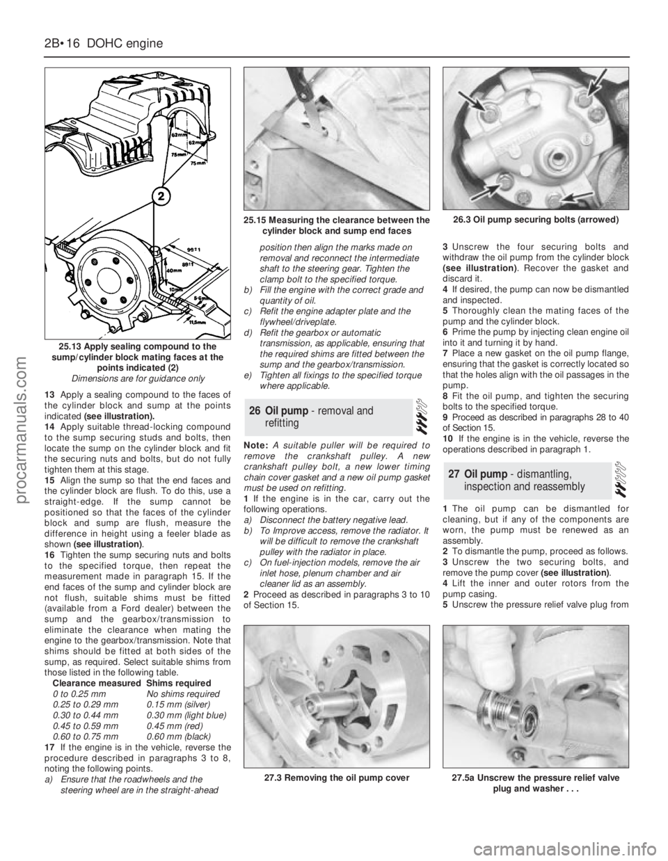
13Apply a sealing compound to the faces of
the cylinder block and sump at the points
indicated(see illustration).
14Apply suitable thread-locking compound
to the sump securing studs and bolts, then
locate the sump on the cylinder block and fit
the securing nuts and bolts, but do not fully
tighten them at this stage.
15Align the sump so that the end faces and
the cylinder block are flush. To do this, use a
straight-edge. If the sump cannot be
positioned so that the faces of the cylinder
block and sump are flush, measure the
difference in height using a feeler blade as
shown (see illustration).
16Tighten the sump securing nuts and bolts
to the specified torque, then repeat the
measurement made in paragraph 15. If the
end faces of the sump and cylinder block are
not flush, suitable shims must be fitted
(available from a Ford dealer) between the
sump and the gearbox/transmission to
eliminate the clearance when mating the
engine to the gearbox/transmission. Note that
shims should be fitted at both sides of the
sump, as required. Select suitable shims from
those listed in the following table.
Clearance measuredShims required
0 to 0.25 mmNo shims required
0.25 to 0.29 mm0.15 mm (silver)
0.30 to 0.44 mm0.30 mm (light blue)
0.45 to 0.59 mm0.45 mm (red)
0.60 to 0.75 mm0.60 mm (black)
17If the engine is in the vehicle, reverse the
procedure described in paragraphs 3 to 8,
noting the following points.
a)Ensure that the roadwheels and the
steering wheel are in the straight-aheadposition then align the marks made on
removal and reconnect the intermediate
shaft to the steering gear. Tighten the
clamp bolt to the specified torque.
b)Fill the engine with the correct grade and
quantity of oil.
c)Refit the engine adapter plate and the
flywheel/driveplate.
d)Refit the gearbox or automatic
transmission, as applicable, ensuring that
the required shims are fitted between the
sump and the gearbox/transmission.
e)Tighten all fixings to the specified torque
where applicable.
Note: A suitable puller will be required to
remove the crankshaft pulley. A new
crankshaft pulley bolt, a new lower timing
chain cover gasket and a new oil pump gasket
must be used on refitting.
1If the engine is in the car, carry out the
following operations.
a)Disconnect the battery negative lead.
b)To Improve access, remove the radiator. It
will be difficult to remove the crankshaft
pulley with the radiator in place.
c)On fuel-injection models, remove the air
inlet hose, plenum chamber and air
cleaner lid as an assembly.
2Proceed as described in paragraphs 3 to 10
of Section 15.3Unscrew the four securing bolts and
withdraw the oil pump from the cylinder block
(see illustration). Recover the gasket and
discard it.
4If desired, the pump can now be dismantled
and inspected.
5Thoroughly clean the mating faces of the
pump and the cylinder block.
6Prime the pump by injecting clean engine oil
into it and turning it by hand.
7Place a new gasket on the oil pump flange,
ensuring that the gasket is correctly located so
that the holes align with the oil passages in the
pump.
8Fit the oil pump, and tighten the securing
bolts to the specified torque.
9Proceed as described in paragraphs 28 to 40
of Section 15.
10If the engine is in the vehicle, reverse the
operations described in paragraph 1.
1The oil pump can be dismantled for
cleaning, but if any of the components are
worn, the pump must be renewed as an
assembly.
2To dismantle the pump, proceed as follows.
3Unscrew the two securing bolts, and
remove the pump cover (see illustration).
4Lift the inner and outer rotors from the
pump casing.
5Unscrew the pressure relief valve plug from
27Oil pump - dismantling,
inspection and reassembly
26Oil pump - removal and
refitting
2B•16DOHCengine
25.13 Apply sealing compound to the
sump/cylinder block mating faces at the
points indicated (2)
Dimensions are for guidance only
27.3 Removing the oil pump cover27.5a Unscrew the pressure relief valve
plug and washer . . .
25.15 Measuring the clearance between the
cylinder block and sump end faces26.3 Oil pump securing bolts (arrowed)
procarmanuals.com
Page 60 of 255
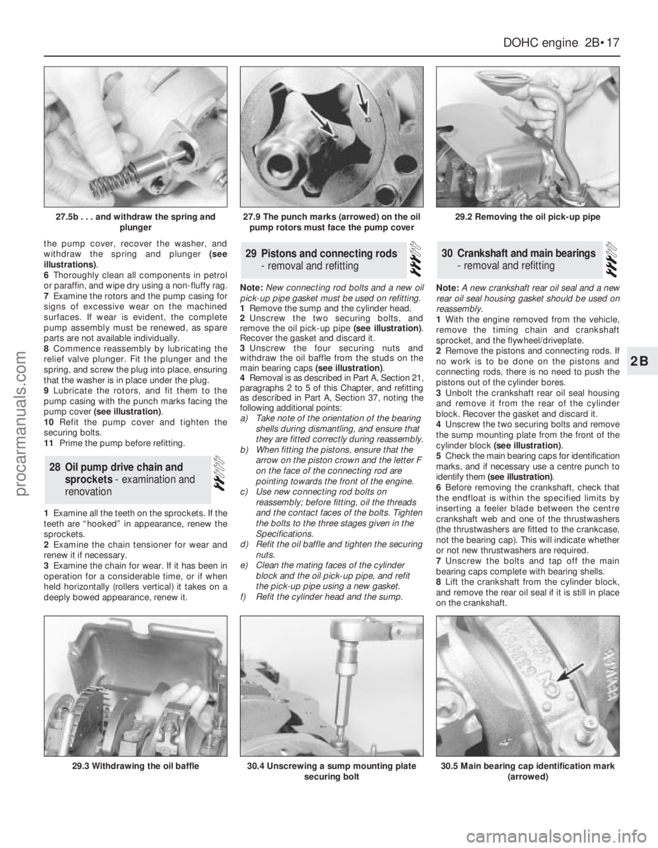
the pump cover, recover the washer, and
withdraw the spring and plunger (see
illustrations).
6Thoroughly clean all components in petrol
or paraffin, and wipe dry using a non-fluffy rag.
7Examine the rotors and the pump casing for
signs of excessive wear on the machined
surfaces. If wear is evident, the complete
pump assembly must be renewed, as spare
parts are not available individually.
8Commence reassembly by lubricating the
relief valve plunger. Fit the plunger and the
spring, and screw the plug into place, ensuring
that the washer is in place under the plug.
9Lubricate the rotors, and fit them to the
pump casing with the punch marks facing the
pump cover (see illustration).
10Refit the pump cover and tighten the
securing bolts.
11Prime the pump before refitting.
1Examine all the teeth on the sprockets. If the
teeth are “hooked” in appearance, renew the
sprockets.
2Examine the chain tensioner for wear and
renew it if necessary.
3Examine the chain for wear. If it has been in
operation for a considerable time, or if when
held horizontally (rollers vertical) it takes on a
deeply bowed appearance, renew it.Note: New connecting rod bolts and a new oil
pick-up pipe gasket must be used on refitting.
1Remove the sump and the cylinder head.
2Unscrew the two securing bolts, and
remove the oil pick-up pipe (see illustration).
Recover the gasket and discard it.
3Unscrew the four securing nuts and
withdraw the oil baffle from the studs on the
main bearing caps (see illustration).
4Removal is as described in Part A, Section 21,
paragraphs 2 to 5 of this Chapter, and refitting
as described in Part A, Section 37, noting the
following additional points:
a)Take note of the orientation of the bearing
shells during dismantling, and ensure that
they are fitted correctly during reassembly.
b)When fitting the pistons, ensure that the
arrow on the piston crown and the letter F
on the face of the connecting rod are
pointing towards the front of the engine.
c)Use new connecting rod bolts on
reassembly; before fitting, oil the threads
and the contact faces of the bolts. Tighten
the bolts to the three stages given in the
Specifications.
d)Refit the oil baffle and tighten the securing
nuts.
e)Clean the mating faces of the cylinder
block and the oil pick-up pipe, and refit
the pick-up pipe using a new gasket.
f)Refit the cylinder head and the sump.Note: A new crankshaft rear oil seal and a new
rear oil seal housing gasket should be used on
reassembly.
1With the engine removed from the vehicle,
remove the timing chain and crankshaft
sprocket, and the flywheel/driveplate.
2Remove the pistons and connecting rods. If
no work is to be done on the pistons and
connecting rods, there is no need to push the
pistons out of the cylinder bores.
3Unbolt the crankshaft rear oil seal housing
and remove it from the rear of the cylinder
block. Recover the gasket and discard it.
4Unscrew the two securing bolts and remove
the sump mounting plate from the front of the
cylinder block (see illustration).
5Check the main bearing caps for identification
marks, and if necessary use a centre punch to
identify them (see illustration).
6Before removing the crankshaft, check that
the endfloat is within the specified limits by
inserting a feeler blade between the centre
crankshaft web and one of the thrustwashers
(the thrustwashers are fitted to the crankcase,
not the bearing cap). This will indicate whether
or not new thrustwashers are required.
7Unscrew the bolts and tap off the main
bearing caps complete with bearing shells.
8Lift the crankshaft from the cylinder block,
and remove the rear oil seal if it is still in place
on the crankshaft.30Crankshaft and main bearings
- removal and refitting29Pistons and connecting rods
- removal and refitting
28Oil pump drive chain and
sprockets - examination and
renovation
DOHCengine 2B•17
2B
27.5b . . . and withdraw the spring and
plunger27.9 The punch marks (arrowed) on the oil
pump rotors must face the pump cover29.2 Removing the oil pick-up pipe
29.3 Withdrawing the oil baffle30.4 Unscrewing a sump mounting plate
securing bolt30.5 Main bearing cap identification mark
(arrowed)
procarmanuals.com
Page 61 of 255
9Extract the bearing shells, and recover the
thrustwashers, keeping them identified for
location.
10The crankshaft and bearings can be
examined and if necessary renovated.
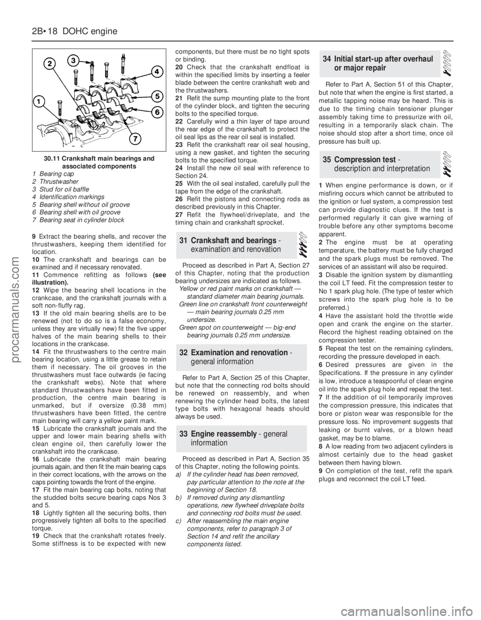
11Commence refitting as follows(see
illustration).
12Wipe the bearing shell locations in the
crankcase, and the crankshaft journals with a
soft non-fluffy rag.
13If the old main bearing shells are to be
renewed (not to do so is a false economy,
unless they are virtually new) fit the five upper
halves of the main bearing shells to their
locations in the crankcase.
14Fit the thrustwashers to the centre main
bearing location, using a little grease to retain
them if necessary. The oil grooves in the
thrustwashers must face outwards (ie facing
the crankshaft webs). Note that where
standard thrustwashers have been fitted in
production, the centre main bearing is
unmarked, but if oversize (0.38 mm)
thrustwashers have been fitted, the centre
main bearing will carry a yellow paint mark.
15Lubricate the crankshaft journals and the
upper and lower main bearing shells with
clean engine oil, then carefully lower the
crankshaft into the crankcase.
16Lubricate the crankshaft main bearing
journals again, and then fit the main bearing caps
in their correct locations, with the arrows on the
caps pointing towards the front of the engine.
17Fit the main bearing cap bolts, noting that
the studded bolts secure bearing caps Nos 3
and 5.
18Lightly tighten all the securing bolts, then
progressively tighten all bolts to the specified
torque.
19Check that the crankshaft rotates freely.
Some stiffness is to be expected with newcomponents, but there must be no tight spots
or binding.
20Check that the crankshaft endfloat is
within the specified limits by inserting a feeler
blade between the centre crankshaft web and
the thrustwashers.
21Refit the sump mounting plate to the front
of the cylinder block, and tighten the securing
bolts to the specified torque.
22Carefully wind a thin layer of tape around
the rear edge of the crankshaft to protect the
oil seal lips as the rear oil seal is installed.
23Refit the crankshaft rear oil seal housing,
using a new gasket, and tighten the securing
bolts to the specified torque.
24Install the new oil seal with reference to
Section 24.
25With the oil seal installed, carefully pull the
tape from the edge of the crankshaft.
26Refit the pistons and connecting rods as
described previously in this Chapter.
27Refit the flywheel/driveplate, and the
timing chain and crankshaft sprocket.
Proceed as described in Part A, Section 27
of this Chapter, noting that the production
bearing undersizes are indicated as follows.
Yellow or red paint marks on crankshaft —
standard diameter main bearing journals.
Green line on crankshaft front counterweight
— main bearing journals 0.25 mm
undersize.
Green spot on counterweight — big-end
bearing journals 0.25 mm undersize.
Refer to Part A, Section 25 of this Chapter,
but note that the connecting rod bolts should
be renewed on reassembly, and when
renewing the cylinder head bolts, the latest
type bolts with hexagonal heads should
always be used.
Proceed as described in Part A, Section 35
of this Chapter, noting the following points.
a)If the cylinder head has been removed,
pay particular attention to the note at the
beginning of Section 18.
b)If removed during any dismantling
operations, new flywheel driveplate bolts
and connecting rod bolts must be used.
c)After reassembling the main engine
components, refer to paragraph 3 of
Section 14 and refit the ancillary
components listed.Refer to Part A, Section 51 of this Chapter,
but note that when the engine is first started, a
metallic tapping noise may be heard. This is
due to the timing chain tensioner plunger
assembly taking time to pressurize with oil,
resulting in a temporarily slack chain. The
noise should stop after a short time, once oil
pressure has built up.
1When engine performance is down, or if
misfiring occurs which cannot be attributed to
the ignition or fuel system, a compression test
can provide diagnostic clues. If the test is
performed regularly it can give warning of
trouble before any other symptoms become
apparent.
2The engine must be at operating
temperature, the battery must be fully charged
and the spark plugs must be removed. The
services of an assistant will also be required.
3Disable the ignition system by dismantling
the coil LT feed. Fit the compression tester to
No 1 spark plug hole. (The type of tester which
screws into the spark plug hole is to be
preferred.)
4Have the assistant hold the throttle wide
open and crank the engine on the starter.
Record the highest reading obtained on the
compression tester.
5Repeat the test on the remaining cylinders,
recording the pressure developed in each.
6Desired pressures are given in the
Specifications. If the pressure in any cylinder
is low, introduce a teaspoonful of clean engine
oil into the spark plug hole and repeat the test.
7If the addition of oil temporarily improves
the compression pressure, this indicates that
bore or piston wear was responsible for the
pressure loss. No improvement suggests that
leaking or burnt valves, or a blown head
gasket, may be to blame.
8A low reading from two adjacent cylinders is
almost certainly due to the head gasket
between them having blown.
9On completion of the test, refit the spark
plugs and reconnect the coil LT feed.
35Compression test -
description and interpretation
34Initial start-up after overhaul
or major repair
33Engine reassembly - general
information
32Examination and renovation -
general information
31Crankshaft and bearings -
examination and renovation
2B•18DOHCengine
30.11 Crankshaft main bearings and
associated components
1 Bearing cap
2 Thrustwasher
3 Stud for oil baffle
4 Identification markings
5 Bearing shell without oil groove
6 Bearing shell with oil groove
7 Bearing seat in cylinder block
procarmanuals.com
Page 66 of 255
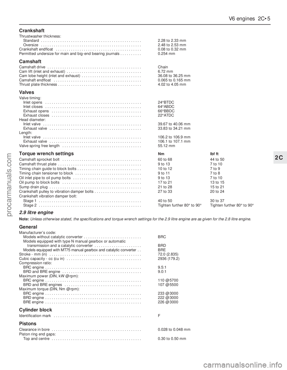
V6 engines 2C•5
2C
Crankshaft
Thrustwasher thickness:
Standard . . . . . . . . . . . . . . . . . . . . . . . . . . . . . . . . . . . . . . . . . . . . . . .2.28 to 2.33 mm
Oversize . . . . . . . . . . . . . . . . . . . . . . . . . . . . . . . . . . . . . . . . . . . . . . .2.48 to 2.53 mm
Crankshaft endfloat . . . . . . . . . . . . . . . . . . . . . . . . . . . . . . . . . . . . . . . .0.08to 0.32 mm
Permitted undersize for main and big-end bearing journals . . . . . . . . . .0.254 mm
Camshaft
Camshaft drive . . . . . . . . . . . . . . . . . . . . . . . . . . . . . . . . . . . . . . . . . . . .Chain
Cam lift (inlet and exhaust) . . . . . . . . . . . . . . . . . . . . . . . . . . . . . . . . . . .6.72 mm
Cam lobe height (inlet and exhaust) . . . . . . . . . . . . . . . . . . . . . . . . . . . .36.08 to 36.25 mm
Camshaft endfloat . . . . . . . . . . . . . . . . . . . . . . . . . . . . . . . . . . . . . . . . .0.065 to 0.165 mm
Thrust plate thickness . . . . . . . . . . . . . . . . . . . . . . . . . . . . . . . . . . . . . . .4.02 to 4.05 mm
Valves
Valve timing:
Inlet opens . . . . . . . . . . . . . . . . . . . . . . . . . . . . . . . . . . . . . . . . . . . . .24°BTDC
Inlet closes . . . . . . . . . . . . . . . . . . . . . . . . . . . . . . . . . . . . . . . . . . . . .64°ABDC
Exhaust opens . . . . . . . . . . . . . . . . . . . . . . . . . . . . . . . . . . . . . . . . . .66°BBDC
Exhaust closes . . . . . . . . . . . . . . . . . . . . . . . . . . . . . . . . . . . . . . . . . .22°ATDC
Head diameter:
Inlet valve . . . . . . . . . . . . . . . . . . . . . . . . . . . . . . . . . . . . . . . . . . . . . .39.67 to 40.06 mm
Exhaust valve . . . . . . . . . . . . . . . . . . . . . . . . . . . . . . . . . . . . . . . . . . .33.83 to 34.21 mm
Length:
Inlet valve . . . . . . . . . . . . . . . . . . . . . . . . . . . . . . . . . . . . . . . . . . . . . .106.2 to 106.9 mm
Exhaust valve . . . . . . . . . . . . . . . . . . . . . . . . . . . . . . . . . . . . . . . . . . .106.1 to 107.1 mm
Valve spring free length . . . . . . . . . . . . . . . . . . . . . . . . . . . . . . . . . . . . .55.12 mm
Torque wrench settingsNmlbf ft
Camshaft sprocket bolt . . . . . . . . . . . . . . . . . . . . . . . . . . . . . . . . . . . . .60 to 6844 to 50
Camshaft thrust plate . . . . . . . . . . . . . . . . . . . . . . . . . . . . . . . . . . . . . . .9 to 137 to 10
Timing chain guide to block bolts . . . . . . . . . . . . . . . . . . . . . . . . . . . . . .10 to 127 to 9
Timing chain tensioner to block . . . . . . . . . . . . . . . . . . . . . . . . . . . . . . .9 to 117 to 8
Oil inlet pipe to oil pump bolts . . . . . . . . . . . . . . . . . . . . . . . . . . . . . . . .9 to 137 to 10
Oil pump to block bolts . . . . . . . . . . . . . . . . . . . . . . . . . . . . . . . . . . . . .17 to 2113 to 15
Sump drain plug . . . . . . . . . . . . . . . . . . . . . . . . . . . . . . . . . . . . . . . . . . .21 to 2815to 21
Crankshaft pulley to vibration damper bolts . . . . . . . . . . . . . . . . . . . . . .27 to 3320 to 24
Crankshaft vibration damper bolt:
Stage 1 . . . . . . . . . . . . . . . . . . . . . . . . . . . . . . . . . . . . . . . . . . . . . . . .40 to 5030 to 37
Stage 2 . . . . . . . . . . . . . . . . . . . . . . . . . . . . . . . . . . . . . . . . . . . . . . . .Tighten further 80°to 90°Tighten further 80°to 90°
2.9 litre engine
Note: Unless otherwise stated, the specifications and torque wrench settings for the 2.9 litre engine are as given for the 2.8 litre engine.
General
Manufacturer’s code:
Models without catalytic converter . . . . . . . . . . . . . . . . . . . . . . . . . . .BRC
Models equipped with type N manual gearbox or automatic
transmission and a catalytic converter . . . . . . . . . . . . . . . . . . . . . .BRD
Models equipped with MT75 manual gearbox and catalytic converter . .BRE
Stroke - mm (in) . . . . . . . . . . . . . . . . . . . . . . . . . . . . . . . . . . . . . . . . . . .72.0 (2.835)
Cubic capacity - cc (cu in) . . . . . . . . . . . . . . . . . . . . . . . . . . . . . . . . . . .2936 (179.2)
Compression ratio:
BRC engine . . . . . . . . . . . . . . . . . . . . . . . . . . . . . . . . . . . . . . . . . . . . .9.5:1
BRD and BRE engine . . . . . . . . . . . . . . . . . . . . . . . . . . . . . . . . . . . . .9.0:1
Maximum power (DIN, kW @ rpm):
BRC engine . . . . . . . . . . . . . . . . . . . . . . . . . . . . . . . . . . . . . . . . . . . . .110 @ 5700
BRD and BRE engines . . . . . . . . . . . . . . . . . . . . . . . . . . . . . . . . . . . .107 @ 5500
Maximum torque (DIN, Nm @ rpm):
BRC engine . . . . . . . . . . . . . . . . . . . . . . . . . . . . . . . . . . . . . . . . . . . . .233 @ 3000
BRD engine . . . . . . . . . . . . . . . . . . . . . . . . . . . . . . . . . . . . . . . . . . . . .222 @ 3000
BRE engine . . . . . . . . . . . . . . . . . . . . . . . . . . . . . . . . . . . . . . . . . . . . .226 @ 3000
Cylinder block
Identification mark . . . . . . . . . . . . . . . . . . . . . . . . . . . . . . . . . . . . . . . . .F
Pistons
Clearance in bore . . . . . . . . . . . . . . . . . . . . . . . . . . . . . . . . . . . . . . . . . .0.028 to 0.048 mm
Piston ring end gaps:
Top and centre . . . . . . . . . . . . . . . . . . . . . . . . . . . . . . . . . . . . . . . . . .0.30 to 0.50 mm
procarmanuals.com
Page 73 of 255
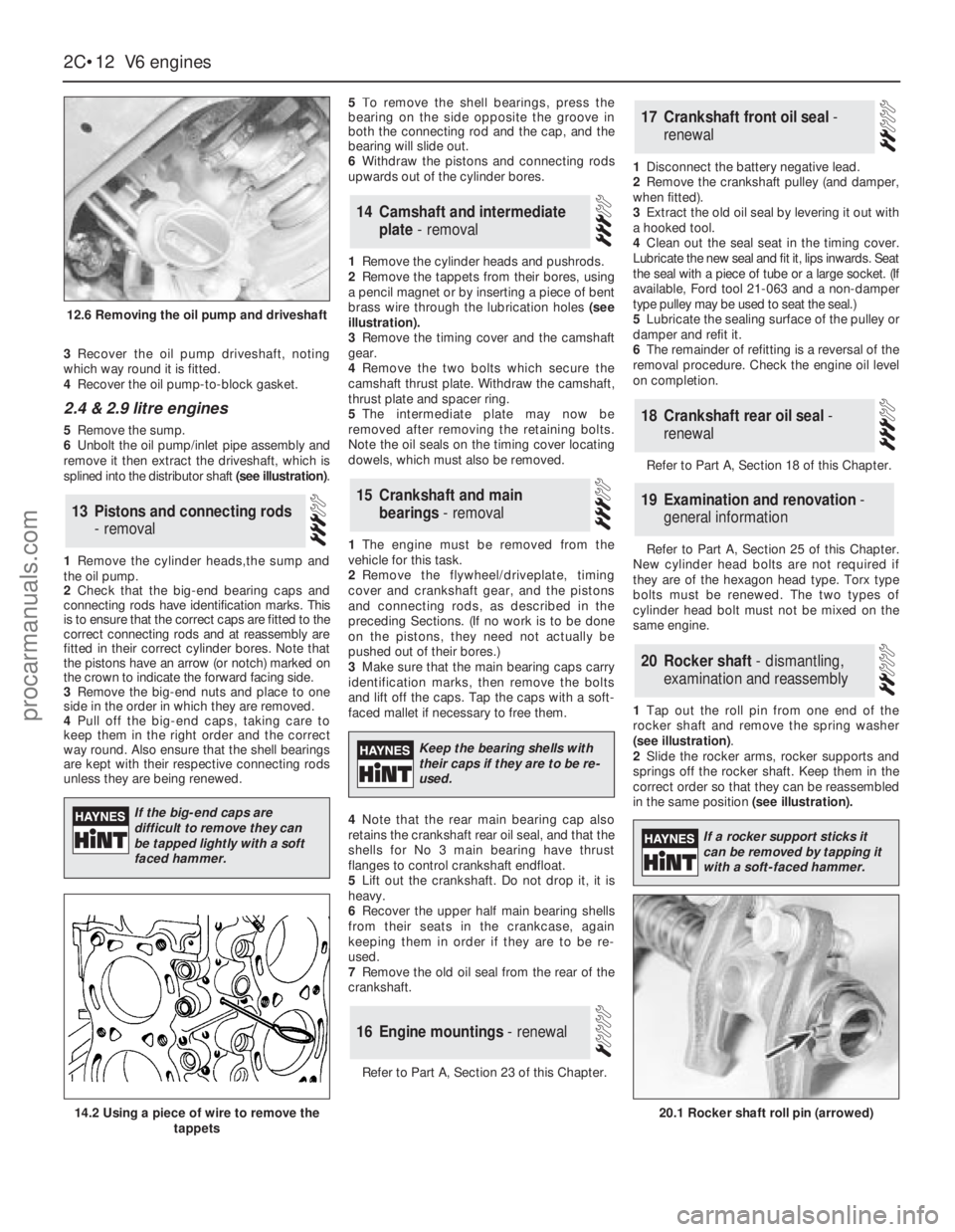
3Recover the oil pump driveshaft, noting
which way round it is fitted.
4Recover the oil pump-to-block gasket.
2.4 & 2.9 litre engines
5Remove the sump.
6Unbolt the oil pump/inlet pipe assembly and
remove it then extract the driveshaft, which is
splined into the distributor shaft (see illustration).
1Remove the cylinder heads,the sump and
the oil pump.
2Check that the big-end bearing caps and
connecting rods have identification marks. This
is to ensure that the correct caps are fitted to the
correct connecting rods and at reassembly are
fitted in their correct cylinder bores. Note that
the pistons have an arrow (or notch) marked on
the crown to indicate the forward facing side.
3Remove the big-end nuts and place to one
side in the order in which they are removed.
4Pull off the big-end caps, taking care to
keep them in the right order and the correct
way round. Also ensure that the shell bearings
are kept with their respective connecting rods
unless they are being renewed.5To remove the shell bearings, press the
bearing on the side opposite the groove in
both the connecting rod and the cap, and the
bearing will slide out.
6Withdraw the pistons and connecting rods
upwards out of the cylinder bores.
1Remove the cylinder heads and pushrods.
2Remove the tappets from their bores, using
a pencil magnet or by inserting a piece of bent
brass wire through the lubrication holes (see
illustration).
3Remove the timing cover and the camshaft
gear.
4Remove the two bolts which secure the
camshaft thrust plate. Withdraw the camshaft,
thrust plate and spacer ring.
5The intermediate plate may now be
removed after removing the retaining bolts.
Note the oil seals on the timing cover locating
dowels, which must also be removed.
1The engine must be removed from the
vehicle for this task.
2Remove the flywheel/driveplate, timing
cover and crankshaft gear, and the pistons
and connecting rods, as described in the
preceding Sections. (If no work is to be done
on the pistons, they need not actually be
pushed out of their bores.)
3Make sure that the main bearing caps carry
identification marks, then remove the bolts
and lift off the caps. Tap the caps with a soft-
faced mallet if necessary to free them.
4Note that the rear main bearing cap also
retains the crankshaft rear oil seal, and that the
shells for No 3 main bearing have thrust
flanges to control crankshaft endfloat.
5Lift out the crankshaft. Do not drop it, it is
heavy.
6Recover the upper half main bearing shells
from their seats in the crankcase, again
keeping them in order if they are to be re-
used.
7Remove the old oil seal from the rear of the
crankshaft.
Refer to Part A, Section 23 of this Chapter.1Disconnect the battery negative lead.
2Remove the crankshaft pulley (and damper,
when fitted).
3Extract the old oil seal by levering it out with
a hooked tool.
4Clean out the seal seat in the timing cover.
Lubricate the new seal and fit it, lips inwards. Seat
the seal with a piece of tube or a large socket. (If
available, Ford tool 21-063 and a non-damper
type pulley may be used to seat the seal.)
5Lubricate the sealing surface of the pulley or
damper and refit it.
6The remainder of refitting is a reversal of the
removal procedure. Check the engine oil level
on completion.
Refer to Part A, Section 18 of this Chapter.
Refer to Part A, Section 25 of this Chapter.
New cylinder head bolts are not required if
they are of the hexagon head type. Torx type
bolts must be renewed. The two types of
cylinder head bolt must not be mixed on the
same engine.
1Tap out the roll pin from one end of the
rocker shaft and remove the spring washer
(see illustration).
2Slide the rocker arms, rocker supports and
springs off the rocker shaft. Keep them in the
correct order so that they can be reassembled
in the same position (see illustration).
20Rocker shaft - dismantling,
examination and reassembly
19Examination and renovation -
general information
18Crankshaft rear oil seal -
renewal
17Crankshaft front oil seal -
renewal
16Engine mountings - renewal
15Crankshaft and main
bearings - removal
14Camshaft and intermediate
plate - removal
13Pistons and connecting rods
- removal
2C•12V6 engines
12.6 Removing the oil pump and driveshaft
20.1 Rocker shaft roll pin (arrowed)14.2 Using a piece of wire to remove the
tappets
If the big-end caps are
difficult to remove they can
be tapped lightly with a soft
faced hammer.
Keep the bearing shells with
their caps if they are to be re-
used.
If a rocker support sticks it
can be removed by tapping it
with a soft-faced hammer.
procarmanuals.com
Page 75 of 255
9Inspect the valve springs, if possible
comparing their free length with new springs.
Renew the springs anyway if they have been in
use for 20 000 miles (32 000 km) or more.
10Use a straight-edge and feeler blades to
check that the cylinder head mating faces are
not distorted. If they are, have the heads
resurfaced by an engineering works.
11Commence reassembly by oiling a valve
stem and inserting the valve into its guide.
Cover the collet grooves with adhesive tape
and press the new valve stem oil seal down
the stem, using a suitable tube to press the
seals home. Note that the inlet valve seals are
rubber and the exhaust seals nylon. On the 2.8
litre engine, oversize exhaust valve seals must
be used when valves with oversize stems are
fitted. Remove the adhesive tape.
12Fit the valve spring and spring retainer.
Compress the spring and fit the collets, using
a dab of grease to hold them in position.
Carefully release the compressor.
13Tap the valve stem smartly with a mallet to
seat the components.
14Repeat the process on the remaining valves.
Refer to Part A, Section 28 of this Chapter.
The main bearing caps should be fitted, and
their bolts tightened to the specified torque,
when making bore measurements.
Refer to Part A, Section 29 of this Chapter.
1Refer to Part A, Section 27 of this Chapter for
the examination procedure. Note that regrinding
of this crankshaft is not permitted, so if significant
journal wear is present, a new crankshaft (and
new bearing shells) must be fitted.
2As with the SOHC engine, oversize main
bearing parent bores may be encountered.
These are marked with paint stripes on the
bearing caps, corresponding paint marks on
the bearing shells and identification codes on
the backs of the bearing shells.
3On the 2.4 litre engine, separate
thrustwashers are used to control crankshaft
endfloat. On the 2.9 litre engine, No 3 main
bearing shells have integral thrust flanges.
2.8 litre engine
1If oil pump wear is suspected, check the
cost and availability of new parts and the cost
of a new pump. Examine the pump and then
decide whether renewal or repair is the best
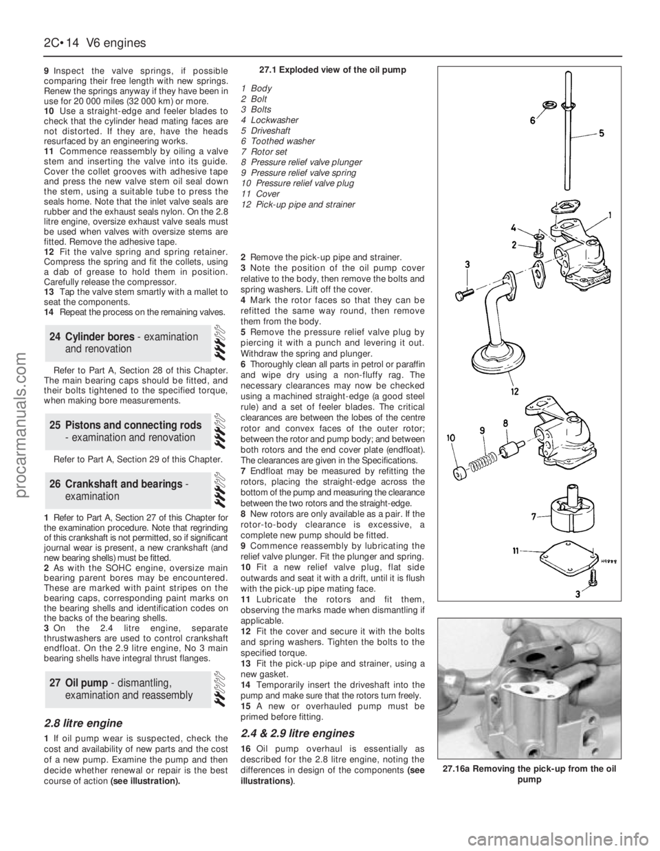
course of action (see illustration).2Remove the pick-up pipe and strainer.
3Note the position of the oil pump cover
relative to the body, then remove the bolts and
spring washers. Lift off the cover.
4Mark the rotor faces so that they can be
refitted the same way round, then remove
them from the body.
5Remove the pressure relief valve plug by
piercing it with a punch and levering it out.
Withdraw the spring and plunger.
6Thoroughly clean all parts in petrol or paraffin
and wipe dry using a non-fluffy rag. The
necessary clearances may now be checked
using a machined straight-edge (a good steel
rule) and a set of feeler blades. The critical
clearances are between the lobes of the centre
rotor and convex faces of the outer rotor;
between the rotor and pump body; and between
both rotors and the end cover plate (endfloat).
The clearances are given in the Specifications.
7Endfloat may be measured by refitting the
rotors, placing the straight-edge across the
bottom of the pump and measuring the clearance
between the two rotors and the straight-edge.
8New rotors are only available as a pair. If the
rotor-to-body clearance is excessive, a
complete new pump should be fitted.
9Commence reassembly by lubricating the
relief valve plunger. Fit the plunger and spring.
10Fit a new relief valve plug, flat side
outwards and seat it with a drift, until it is flush
with the pick-up pipe mating face.
11Lubricate the rotors and fit them,
observing the marks made when dismantling if
applicable.
12Fit the cover and secure it with the bolts
and spring washers. Tighten the bolts to the
specified torque.
13Fit the pick-up pipe and strainer, using a
new gasket.
14Temporarily insert the driveshaft into the
pump and make sure that the rotors turn freely.
15A new or overhauled pump must be
primed before fitting.2.4 & 2.9 litre engines
16Oil pump overhaul is essentially as
described for the 2.8 litre engine, noting the
differences in design of the components (see
illustrations).
27Oil pump - dismantling,
examination and reassembly
26Crankshaft and bearings -
examination
25Pistons and connecting rods
- examination and renovation
24Cylinder bores - examination
and renovation
2C•14V6 engines
27.16a Removing the pick-up from the oil
pump
27.1 Exploded view of the oil pump
1 Body
2 Bolt
3 Bolts
4 Lockwasher
5 Driveshaft
6 Toothed washer
7 Rotor set
8 Pressure relief valve plunger
9 Pressure relief valve spring
10 Pressure relief valve plug
11 Cover
12 Pick-up pipe and strainer
procarmanuals.com
Page 78 of 255
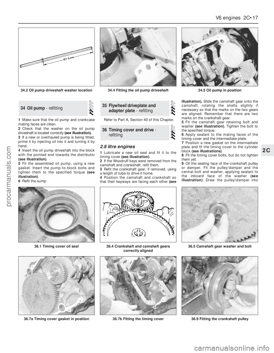
1Make sure that the oil pump and crankcase
mating faces are clean.
2Check that the washer on the oil pump
driveshaft is located correctly (see illustration).
3If a new or overhauled pump is being fitted,
prime it by injecting oil into it and turning it by
hand.
4Insert the oil pump driveshaft into the block
with the pointed end towards the distributor
(see illustration).
5Fit the assembled oil pump, using a new
gasket. Insert the pump-to-block bolts and
tighten them to the specified torque (see
illustration).
6Refit the sump.Refer to Part A, Section 40 of this Chapter.
2.8 litre engines
1Lubricate a new oil seal and fit it to the
timing cover (see illustration).
2If the Woodruff keys were removed from the
camshaft and crankshaft, refit them.
3Refit the crankshaft gear, if removed, using
a length of tube to drive it home.
4Position the camshaft and crankshaft so
that their keyways are facing each other(seeillustration).Slide the camshaft gear onto the
camshaft, rotating the shafts slightly if
necessary so that the marks on the two gears
are aligned. Remember that there are two
marks on the crankshaft gear.
5Fit the camshaft gear retaining bolt and
washer(see illustration).Tighten the bolt to
the specified torque.
6Apply sealant to the mating faces of the
timing cover and the intermediate plate.
7Position a new gasket on the intermediate
plate and fit the timing cover to the cylinder
block (see illustrations).
8Fit the timing cover bolts, but do not tighten
them yet.
9Oil the sealing face of the crankshaft pulley
or damper. Fit the pulley/damper and the
central bolt and washer, applying sealant to
the inboard face of the washer (see
illustration). Draw the pulley/damper into
36Timing cover and drive -
refitting
35Flywheel/driveplate and
adapter plate - refitting34Oil pump - refitting
V6 engines 2C•17
2C
34.2 Oil pump driveshaft washer location34.4 Fitting the oil pump driveshaft34.5 Oil pump in position
36.7a Timing cover gasket in position
36.1 Timing cover oil seal36.5 Camshaft gear washer and bolt36.4 Crankshaft and camshaft gears
correctly aligned
36.7b Fitting the timing cover36.9 Fitting the crankshaft pulley
procarmanuals.com