washer FORD GRANADA 1985 Service Workshop Manual
[x] Cancel search | Manufacturer: FORD, Model Year: 1985, Model line: GRANADA, Model: FORD GRANADA 1985Pages: 255, PDF Size: 14.98 MB
Page 178 of 255
Chapter 13
Body electrical system
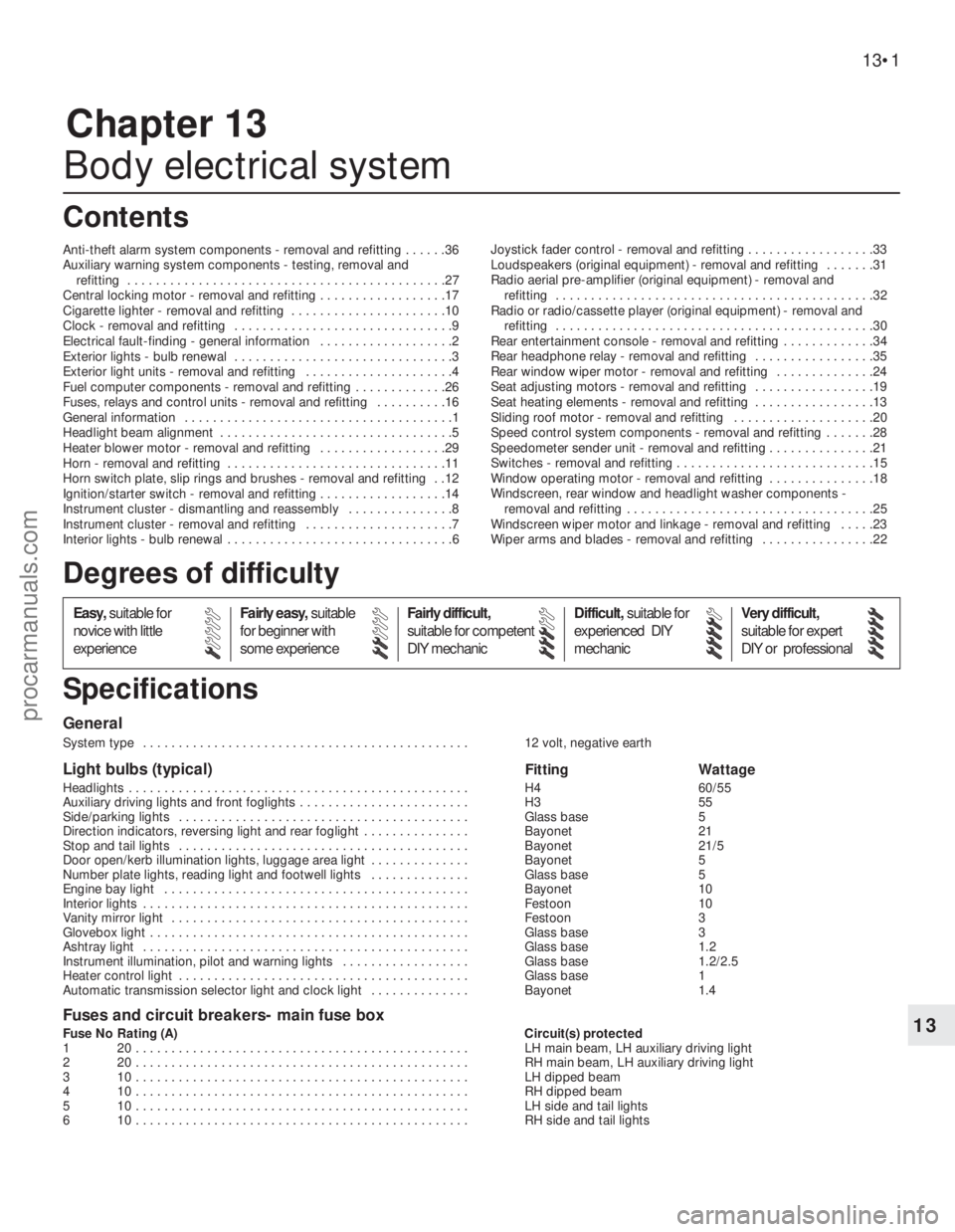
Anti-theft alarm system components - removal and refitting . . . . . .36
Auxiliary warning system components - testing, removal and
refitting . . . . . . . . . . . . . . . . . . . . . . . . . . . . . . . . . . . . . . . . . . . . .27
Central locking motor - removal and refitting . . . . . . . . . . . . . . . . . .17
Cigarette lighter - removal and refitting . . . . . . . . . . . . . . . . . . . . . .10
Clock - removal and refitting . . . . . . . . . . . . . . . . . . . . . . . . . . . . . . .9
Electrical fault-finding - general information . . . . . . . . . . . . . . . . . . .2
Exterior lights - bulb renewal . . . . . . . . . . . . . . . . . . . . . . . . . . . . . . .3
Exterior light units - removal and refitting . . . . . . . . . . . . . . . . . . . . .4
Fuel computer components - removal and refitting . . . . . . . . . . . . .26
Fuses, relays and control units - removal and refitting . . . . . . . . . .16
General information . . . . . . . . . . . . . . . . . . . . . . . . . . . . . . . . . . . . . .1
Headlight beam alignment . . . . . . . . . . . . . . . . . . . . . . . . . . . . . . . . .5
Heater blower motor - removal and refitting . . . . . . . . . . . . . . . . . .29
Horn - removal and refitting . . . . . . . . . . . . . . . . . . . . . . . . . . . . . . .11
Horn switch plate, slip rings and brushes - removal and refitting . .12
Ignition/starter switch - removal and refitting . . . . . . . . . . . . . . . . . .14
Instrument cluster - dismantling and reassembly . . . . . . . . . . . . . . .8
Instrument cluster - removal and refitting . . . . . . . . . . . . . . . . . . . . .7
Interior lights - bulb renewal . . . . . . . . . . . . . . . . . . . . . . . . . . . . . . . .6Joystick fader control - removal and refitting . . . . . . . . . . . . . . . . . .33
Loudspeakers (original equipment) - removal and refitting . . . . . . .31
Radio aerial pre-amplifier (original equipment) - removal and
refitting . . . . . . . . . . . . . . . . . . . . . . . . . . . . . . . . . . . . . . . . . . . . .32
Radio or radio/cassette player (original equipment) - removal and
refitting . . . . . . . . . . . . . . . . . . . . . . . . . . . . . . . . . . . . . . . . . . . . .30
Rear entertainment console - removal and refitting . . . . . . . . . . . . .34
Rear headphone relay - removal and refitting . . . . . . . . . . . . . . . . .35
Rear window wiper motor - removal and refitting . . . . . . . . . . . . . .24
Seat adjusting motors - removal and refitting . . . . . . . . . . . . . . . . .19
Seat heating elements - removal and refitting . . . . . . . . . . . . . . . . .13
Sliding roof motor - removal and refitting . . . . . . . . . . . . . . . . . . . .20
Speed control system components - removal and refitting . . . . . . .28
Speedometer sender unit - removal and refitting . . . . . . . . . . . . . . .21
Switches - removal and refitting . . . . . . . . . . . . . . . . . . . . . . . . . . . .15
Window operating motor - removal and refitting . . . . . . . . . . . . . . .18
Windscreen, rear window and headlight washer components -
removal and refitting . . . . . . . . . . . . . . . . . . . . . . . . . . . . . . . . . . .25
Windscreen wiper motor and linkage - removal and refitting . . . . .23
Wiper arms and blades - removal and refitting . . . . . . . . . . . . . . . .22
General
System type . . . . . . . . . . . . . . . . . . . . . . . . . . . . . . . . . . . . . . . . . . . . . . 12 volt, negative earth
Light bulbs (typical)Fitting Wattage
Headlights . . . . . . . . . . . . . . . . . . . . . . . . . . . . . . . . . . . . . . . . . . . . . . . . H4 60/55
Auxiliary driving lights and front foglights . . . . . . . . . . . . . . . . . . . . . . . . H3 55
Side/parking lights . . . . . . . . . . . . . . . . . . . . . . . . . . . . . . . . . . . . . . . . . Glass base 5
Direction indicators, reversing light and rear foglight . . . . . . . . . . . . . . . Bayonet 21
Stop and tail lights . . . . . . . . . . . . . . . . . . . . . . . . . . . . . . . . . . . . . . . . . Bayonet 21/5
Door open/kerb illumination lights, luggage area light . . . . . . . . . . . . . . Bayonet 5
Number plate lights, reading light and footwell lights . . . . . . . . . . . . . . Glass base 5
Engine bay light . . . . . . . . . . . . . . . . . . . . . . . . . . . . . . . . . . . . . . . . . . . Bayonet 10
Interior lights . . . . . . . . . . . . . . . . . . . . . . . . . . . . . . . . . . . . . . . . . . . . . . Festoon 10
Vanity mirror light . . . . . . . . . . . . . . . . . . . . . . . . . . . . . . . . . . . . . . . . . . Festoon 3
Glovebox light . . . . . . . . . . . . . . . . . . . . . . . . . . . . . . . . . . . . . . . . . . . . . Glass base 3
Ashtray light . . . . . . . . . . . . . . . . . . . . . . . . . . . . . . . . . . . . . . . . . . . . . . Glass base 1.2
Instrument illumination, pilot and warning lights . . . . . . . . . . . . . . . . . . Glass base 1.2/2.5
Heater control light . . . . . . . . . . . . . . . . . . . . . . . . . . . . . . . . . . . . . . . . . Glass base 1
Automatic transmission selector light and clock light . . . . . . . . . . . . . . Bayonet 1.4
Fuses and circuit breakers- main fuse box
Fuse No Rating (A) Circuit(s) protected
1 20 . . . . . . . . . . . . . . . . . . . . . . . . . . . . . . . . . . . . . . . . . . . . . . . LH main beam, LH auxiliary driving light
2 20 . . . . . . . . . . . . . . . . . . . . . . . . . . . . . . . . . . . . . . . . . . . . . . . RH main beam, LH auxiliary driving light
3 10 . . . . . . . . . . . . . . . . . . . . . . . . . . . . . . . . . . . . . . . . . . . . . . . LH dipped beam
4 10 . . . . . . . . . . . . . . . . . . . . . . . . . . . . . . . . . . . . . . . . . . . . . . . RH dipped beam
5 10 . . . . . . . . . . . . . . . . . . . . . . . . . . . . . . . . . . . . . . . . . . . . . . . LH side and tail lights
6 10 . . . . . . . . . . . . . . . . . . . . . . . . . . . . . . . . . . . . . . . . . . . . . . . RH side and tail lights
13•1
Easy,suitable for
novice with little
experienceFairly easy,suitable
for beginner with
some experienceFairly difficult,
suitable for competent
DIY mechanicDifficult,suitable for
experienced DIY
mechanicVery difficult,
suitable for expert
DIY or professional
Degrees of difficulty
Specifications Contents
13
procarmanuals.com
Page 179 of 255
13•2Body electrical system
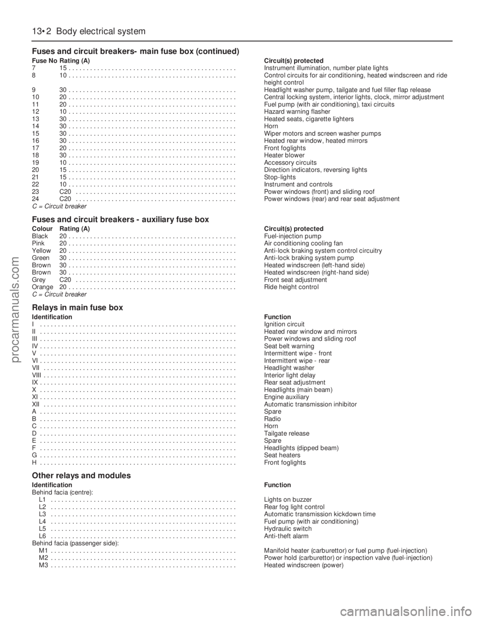
Fuses and circuit breakers- main fuse box (continued)
Fuse NoRating (A)Circuit(s) protected
715 . . . . . . . . . . . . . . . . . . . . . . . . . . . . . . . . . . . . . . . . . . . . . . .Instrument illumination, number plate lights
810 . . . . . . . . . . . . . . . . . . . . . . . . . . . . . . . . . . . . . . . . . . . . . . .Control circuits for air conditioning, heated windscreen and ride
height control
930 . . . . . . . . . . . . . . . . . . . . . . . . . . . . . . . . . . . . . . . . . . . . . . .Headlight washer pump, tailgate and fuel filler flap release
1020 . . . . . . . . . . . . . . . . . . . . . . . . . . . . . . . . . . . . . . . . . . . . . . .Central locking system, interior lights, clock, mirror adjustment
1120 . . . . . . . . . . . . . . . . . . . . . . . . . . . . . . . . . . . . . . . . . . . . . . .Fuel pump (with air conditioning), taxi circuits
1210 . . . . . . . . . . . . . . . . . . . . . . . . . . . . . . . . . . . . . . . . . . . . . . .Hazard warning flasher
1330 . . . . . . . . . . . . . . . . . . . . . . . . . . . . . . . . . . . . . . . . . . . . . . .Heated seats, cigarette lighters
1430 . . . . . . . . . . . . . . . . . . . . . . . . . . . . . . . . . . . . . . . . . . . . . . .Horn
1530 . . . . . . . . . . . . . . . . . . . . . . . . . . . . . . . . . . . . . . . . . . . . . . .Wiper motors and screen washer pumps
1630 . . . . . . . . . . . . . . . . . . . . . . . . . . . . . . . . . . . . . . . . . . . . . . .Heated rear window, heated mirrors
1720 . . . . . . . . . . . . . . . . . . . . . . . . . . . . . . . . . . . . . . . . . . . . . . .Front foglights
1830 . . . . . . . . . . . . . . . . . . . . . . . . . . . . . . . . . . . . . . . . . . . . . . .Heater blower
1910 . . . . . . . . . . . . . . . . . . . . . . . . . . . . . . . . . . . . . . . . . . . . . . .Accessory circuits
2015 . . . . . . . . . . . . . . . . . . . . . . . . . . . . . . . . . . . . . . . . . . . . . . .Direction indicators, reversing lights
2115 . . . . . . . . . . . . . . . . . . . . . . . . . . . . . . . . . . . . . . . . . . . . . . .Stop-lights
2210 . . . . . . . . . . . . . . . . . . . . . . . . . . . . . . . . . . . . . . . . . . . . . . .Instrument and controls
23C20 . . . . . . . . . . . . . . . . . . . . . . . . . . . . . . . . . . . . . . . . . . . . .Power windows (front) and sliding roof
24C20 . . . . . . . . . . . . . . . . . . . . . . . . . . . . . . . . . . . . . . . . . . . . .Power windows (rear) and rear seat adjustment
C = Circuit breaker
Fuses and circuit breakers - auxiliary fuse box
Colour Rating (A)Circuit(s) protected
Black20 . . . . . . . . . . . . . . . . . . . . . . . . . . . . . . . . . . . . . . . . . . . . . . .Fuel-injection pump
Pink20 . . . . . . . . . . . . . . . . . . . . . . . . . . . . . . . . . . . . . . . . . . . . . . .Air conditioning cooling fan
Yellow20 . . . . . . . . . . . . . . . . . . . . . . . . . . . . . . . . . . . . . . . . . . . . . . .Anti-lock braking system control circuitry
Green30 . . . . . . . . . . . . . . . . . . . . . . . . . . . . . . . . . . . . . . . . . . . . . . .Anti-lock braking system pump
Brown30 . . . . . . . . . . . . . . . . . . . . . . . . . . . . . . . . . . . . . . . . . . . . . . .Heated windscreen (left-hand side)
Brown30 . . . . . . . . . . . . . . . . . . . . . . . . . . . . . . . . . . . . . . . . . . . . . . .Heated windscreen (right-hand side)
GreyC20 . . . . . . . . . . . . . . . . . . . . . . . . . . . . . . . . . . . . . . . . . . . . .Front seat adjustment
Orange20 . . . . . . . . . . . . . . . . . . . . . . . . . . . . . . . . . . . . . . . . . . . . . . .Ride height control
C = Circuit breaker
Relays in main fuse box
IdentificationFunction
I . . . . . . . . . . . . . . . . . . . . . . . . . . . . . . . . . . . . . . . . . . . . . . . . . . . . . . .Ignition circuit
II . . . . . . . . . . . . . . . . . . . . . . . . . . . . . . . . . . . . . . . . . . . . . . . . . . . . . . .Heated rear window and mirrors
III . . . . . . . . . . . . . . . . . . . . . . . . . . . . . . . . . . . . . . . . . . . . . . . . . . . . . . .Power windows and sliding roof
IV . . . . . . . . . . . . . . . . . . . . . . . . . . . . . . . . . . . . . . . . . . . . . . . . . . . . . . .Seat belt warning
V . . . . . . . . . . . . . . . . . . . . . . . . . . . . . . . . . . . . . . . . . . . . . . . . . . . . . . .Intermittent wipe - front
VI . . . . . . . . . . . . . . . . . . . . . . . . . . . . . . . . . . . . . . . . . . . . . . . . . . . . . . .Intermittent wipe - rear
VII . . . . . . . . . . . . . . . . . . . . . . . . . . . . . . . . . . . . . . . . . . . . . . . . . . . . . .Headlight washer
VIII . . . . . . . . . . . . . . . . . . . . . . . . . . . . . . . . . . . . . . . . . . . . . . . . . . . . . .Interior light delay
IX . . . . . . . . . . . . . . . . . . . . . . . . . . . . . . . . . . . . . . . . . . . . . . . . . . . . . . .Rear seat adjustment
X . . . . . . . . . . . . . . . . . . . . . . . . . . . . . . . . . . . . . . . . . . . . . . . . . . . . . . .Headlights (main beam)
XI . . . . . . . . . . . . . . . . . . . . . . . . . . . . . . . . . . . . . . . . . . . . . . . . . . . . . . .Engine auxiliary
XII . . . . . . . . . . . . . . . . . . . . . . . . . . . . . . . . . . . . . . . . . . . . . . . . . . . . . .Automatic transmission inhibitor
A . . . . . . . . . . . . . . . . . . . . . . . . . . . . . . . . . . . . . . . . . . . . . . . . . . . . . . .Spare
B . . . . . . . . . . . . . . . . . . . . . . . . . . . . . . . . . . . . . . . . . . . . . . . . . . . . . . .Radio
C . . . . . . . . . . . . . . . . . . . . . . . . . . . . . . . . . . . . . . . . . . . . . . . . . . . . . . .Horn
D . . . . . . . . . . . . . . . . . . . . . . . . . . . . . . . . . . . . . . . . . . . . . . . . . . . . . . .Tailgate release
E . . . . . . . . . . . . . . . . . . . . . . . . . . . . . . . . . . . . . . . . . . . . . . . . . . . . . . .Spare
F . . . . . . . . . . . . . . . . . . . . . . . . . . . . . . . . . . . . . . . . . . . . . . . . . . . . . . .Headlights (dipped beam)
G . . . . . . . . . . . . . . . . . . . . . . . . . . . . . . . . . . . . . . . . . . . . . . . . . . . . . . .Seat heaters
H . . . . . . . . . . . . . . . . . . . . . . . . . . . . . . . . . . . . . . . . . . . . . . . . . . . . . . .Front foglights
Other relays and modules
IdentificationFunction
Behind facia (centre):
L1 . . . . . . . . . . . . . . . . . . . . . . . . . . . . . . . . . . . . . . . . . . . . . . . . . . . .Lights on buzzer
L2 . . . . . . . . . . . . . . . . . . . . . . . . . . . . . . . . . . . . . . . . . . . . . . . . . . . .Rear fog light control
L3 . . . . . . . . . . . . . . . . . . . . . . . . . . . . . . . . . . . . . . . . . . . . . . . . . . . .Automatic transmission kickdown time
L4 . . . . . . . . . . . . . . . . . . . . . . . . . . . . . . . . . . . . . . . . . . . . . . . . . . . .Fuel pump (with air conditioning)
L5 . . . . . . . . . . . . . . . . . . . . . . . . . . . . . . . . . . . . . . . . . . . . . . . . . . . .Hydraulic switch
L6 . . . . . . . . . . . . . . . . . . . . . . . . . . . . . . . . . . . . . . . . . . . . . . . . . . . .Anti-theft alarm
Behind facia (passenger side):
M1 . . . . . . . . . . . . . . . . . . . . . . . . . . . . . . . . . . . . . . . . . . . . . . . . . . . .Manifold heater (carburettor) or fuel pump (fuel-injection)
M2 . . . . . . . . . . . . . . . . . . . . . . . . . . . . . . . . . . . . . . . . . . . . . . . . . . . .Power hold (carburettor) or inspection valve (fuel-injection)
M3 . . . . . . . . . . . . . . . . . . . . . . . . . . . . . . . . . . . . . . . . . . . . . . . . . . . .Heated windscreen (power)
procarmanuals.com
Page 181 of 255
the circuit between the relevant connector and
the battery is problem-free.
13Continue to check the remainder of the
circuit in the same fashion.
14When a point is reached at which no
voltage is present, the problem must lie
between that point and the previous test point
with voltage. Most problems can be traced to
a broken, corroded or loose connection.
Finding a short-circuit
15To check for a short-circuit, first disconnect
the load(s) from the circuit (loads are the
components which draw current from a circuit,
such as bulbs, motors, heating elements, etc).
16Remove the relevant fuse from the circuit,
and connect a circuit tester or voltmeter to the
fuse connections.
17Switch on the circuit, bearing in mind that
some circuits are live only when the ignition
switch is moved to a particular position.
18If voltage is present (indicated either by
the tester bulb lighting or a voltmeter reading),
this means that there is a short-circuit.
19If no voltage is present, but the fuse still
blows with the load(s) connected, this
indicates an internal fault in the load(s).
Finding an earth fault
20The battery negative terminal is connected
to “earth” - the metal of the engine/transmission
and the car body - and most systems are wired
so that they only receive a positive feed, the
current returning via the metal of the car body.
This means that the component mounting andthe body form part of that circuit. Loose or
corroded mountings can therefore cause a range
of electrical faults, ranging from total failure of a
circuit, to a puzzling partial fault. In particular,
lights may shine dimly (especially when another
circuit sharing the same earth is in operation),
motors (eg wiper motors or the radiator cooling
fan motor) may run slowly, and the operation of
one circuit may have an apparently-unrelated
effect on another. Note that on many vehicles,
earth straps are used between certain
components, such as the engine/transmission
and the body, usually where there is no metal-to-
metal contact between components, due to
flexible rubber mountings, etc.
21To check whether a component is properly
earthed, disconnect the battery, and connect
one lead of an ohmmeter to a known good
earth point. Connect the other lead to the wire
or earth connection being tested. The
resistance reading should be zero; if not,
check the connection as follows.
22If an earth connection is thought to be
faulty, dismantle the connection, and clean
back to bare metal both the bodyshell and the
wire terminal, or the component’s earth
connection mating surface. Be careful to
remove all traces of dirt and corrosion, then
use a knife to trim away any paint, so that a
clean metal-to-metal joint is made. On
reassembly, tighten the joint fasteners
securely; if a wire terminal is being refitted, use
serrated washers between the terminal and
the bodyshell, to ensure a clean and secure
connection. When the connection is remade,
prevent the onset of corrosion in the future byapplying a coat of petroleum jelly or silicone-
based grease, or by spraying on (at regular
intervals) a proprietary ignition sealer, or a
water-dispersant lubricant.
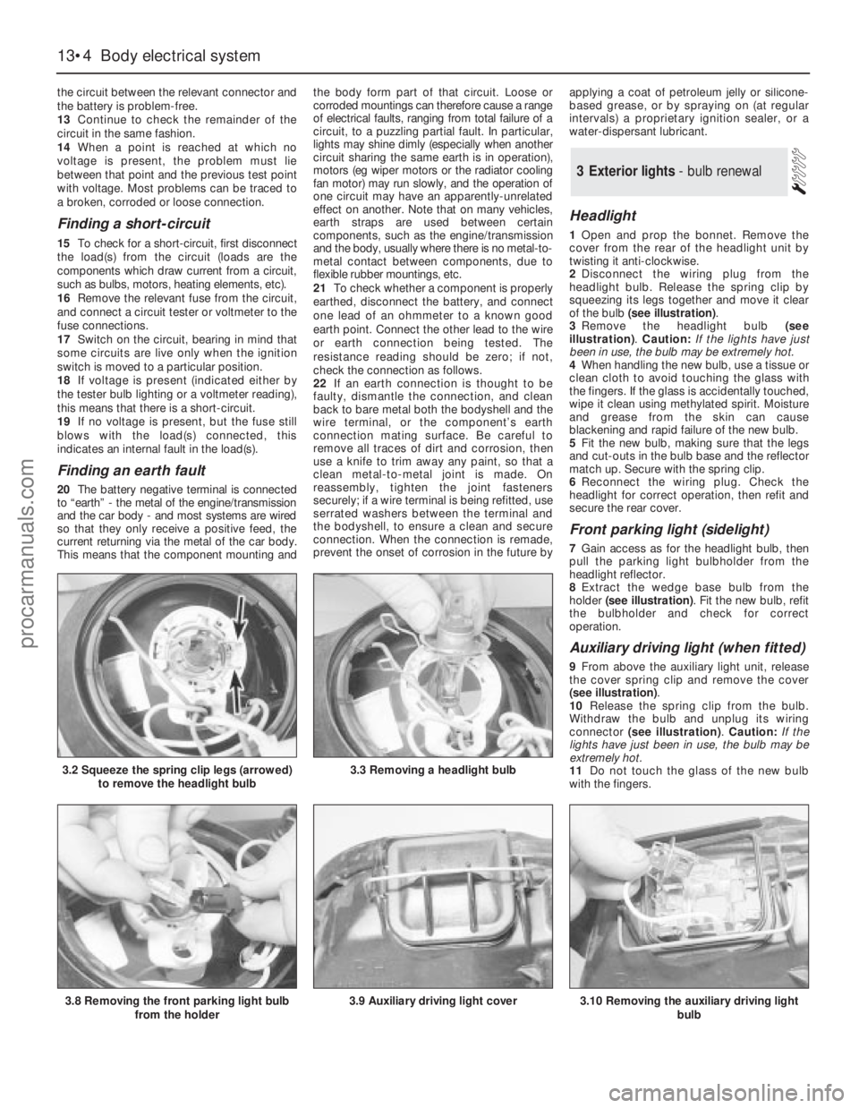
Headlight
1Open and prop the bonnet. Remove the
cover from the rear of the headlight unit by
twisting it anti-clockwise.
2Disconnect the wiring plug from the
headlight bulb. Release the spring clip by
squeezing its legs together and move it clear
of the bulb (see illustration).
3Remove the headlight bulb (see
illustration). Caution: If the lights have just
been in use, the bulb may be extremely hot.
4When handling the new bulb, use a tissue or
clean cloth to avoid touching the glass with
the fingers. If the glass is accidentally touched,
wipe it clean using methylated spirit. Moisture
and grease from the skin can cause
blackening and rapid failure of the new bulb.
5Fit the new bulb, making sure that the legs
and cut-outs in the bulb base and the reflector
match up. Secure with the spring clip.
6Reconnect the wiring plug. Check the
headlight for correct operation, then refit and
secure the rear cover.
Front parking light (sidelight)
7Gain access as for the headlight bulb, then
pull the parking light bulbholder from the
headlight reflector.
8Extract the wedge base bulb from the
holder (see illustration). Fit the new bulb, refit
the bulbholder and check for correct
operation.
Auxiliary driving light (when fitted)
9From above the auxiliary light unit, release
the cover spring clip and remove the cover
(see illustration).
10Release the spring clip from the bulb.
Withdraw the bulb and unplug its wiring
connector (see illustration). Caution: If the
lights have just been in use, the bulb may be
extremely hot.
11Do not touch the glass of the new bulb
with the fingers.
3Exterior lights - bulb renewal
13•4Body electrical system
3.2 Squeeze the spring clip legs (arrowed)
to remove the headlight bulb3.3 Removing a headlight bulb
3.8 Removing the front parking light bulb
from the holder3.9 Auxiliary driving light cover3.10 Removing the auxiliary driving light
bulb
procarmanuals.com
Page 187 of 255
1With the instrument cluster removed, a
particular gauge or other component can be
renewed by following the appropriate parts of
this Section.
2Remove all the light bulbs and holders from
the rear of the panel by twisting them anti-
clockwise.
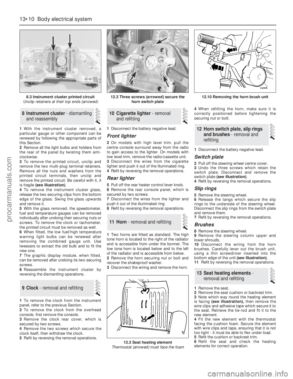
3To remove the printed circuit, unclip and
remove the two multi-plug terminal retainers.
Remove all the nuts and washers from the
printed circuit terminals, then unclip and
remove the printed circuit. Be careful with it, it
is fragile (see illustration).
4To remove the instrument cluster glass,
release the two securing clips from thebottom
edge of the glass. Swing the glass upwards
and remove it.
5With the glass removed, the speedometer,
fuel and temperature gauges can be removed
individually after undoing their securing nuts or
screws. To remove the clock or tachometer,
the printed circuit must be removed as well.
6When fitted, the low fuel/high temperature
warning light bulbs can be renewed after
removing the combined gauge unit. Use
tweezers to extract the old bulb and to fit the
new one.
7The graphic display module, when fitted,
can be removed after undoing its two securing
screws.
8Reassemble the instrument cluster by
reversing the dismantling operations.
1To remove the clock from the instrument
panel, refer to the previous Section.
2To remove the clock from the overhead
console, first remove the console.
3Remove the clock rear cover, which is
secured by two screws.
4Remove the two screws which secure the
clock itself, then withdraw the clock.
5Refit by reversing the removal operations.1Disconnect the battery negative lead.
Front lighter
2On models with high level trim, pull the
centre console surround away from the radio
to gain access to the lighter. On models with
low level trim, remove the radio/cassette unit.
3Disconnect the wires from the cigarette
lighter and push it out of the illuminated ring.
4Refit by reversing the removal operations.
Rear lighter
5Pull off the rear heater control lever knob.
6Remove the rear console panel, which is
secured by two screws.
7Disconnect the wires from the lighter and
push it out of the illuminated ring.
8Refit by reversing the removal operations.
1Two horns are fitted as standard. The high
tone horn is located to the right of the radiator
and is accessible from under the bonnet. The
low tone horn is located below and to the left
of the radiator and is accessible from below.
2Remove the horn securing nut or bolt and
recover the shakeproof washer.
3Disconnect the wiring and remove the horn.4When refitting the horn, make sure it is
correctly positioned before tightening the
securing nut or bolt.
1Disconnect the battery negative lead.
Switch plate
2Pull off the steering wheel centre cover.
3Undo the three screws which retain the
switch plate. Disconnect and remove the
switch plate (see illustration).
4Refit by reversing the removal operations.
Slip rings
5Remove the steering wheel.
6Release the tangs which secure the slip
rings to the underside of the steering wheel.
Disconnect the slip rings from the switch plate
and remove them.
7Refit by reversing the removal operations.
Brushes
8Remove the steering wheel.
9Remove the steering column upper and
lower shrouds.
10Disconnect the wiring from the horn
brushes. Carefully lever out the brush unit,
using a thin screwdriver inserted into the
bottom edge of the unit(see illustration).
11Refit by reversing the removal operations.
1Remove the seat.
2Remove the seat cushion or backrest trim.
3Note which way round the heating element
is facing (see illustration),then remove the
wire clips and adhesive tape which secure it to
the seat. Retrieve the tie-rod and fit it to the
new element.
4Fit the new element with the thermostat
facing the cushion foam. Secure the element
with wire clips and tape, ensuring that it is not
too tight - it must be able to flex under load.
5Refit the cushion or backrest trim.
6Refit the seat and check the heating
elements for correct operation.
13Seat heating elements -
removal and refitting
12Horn switch plate, slip rings
and brushes - removal and
refitting
11Horn - removal and refitting
10Cigarette lighter - removal
and refitting
9Clock - removal and refitting
8Instrument cluster - dismantling
and reassembly
13•10Body electrical system
8.3 Instrument cluster printed circuit
Unclip retainers at their top ends (arrowed)
13.3 Seat heating element
Thermostat (arrowed) must face the foam
12.3 Three screws (arrowed) secure the
horn switch plate12.10 Removing the horn brush unit
procarmanuals.com
Page 192 of 255
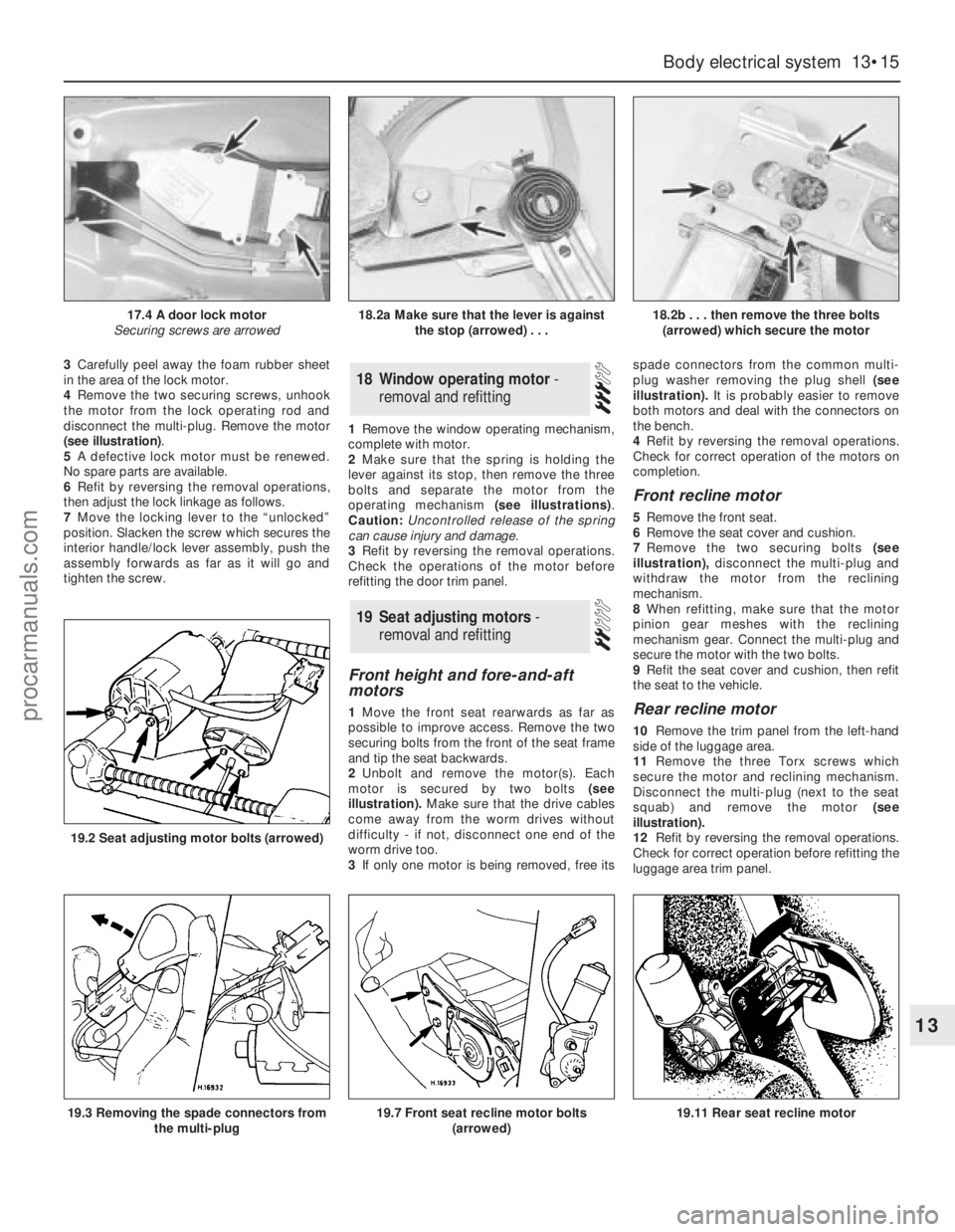
3Carefully peel away the foam rubber sheet
in the area of the lock motor.
4Remove the two securing screws, unhook
the motor from the lock operating rod and
disconnect the multi-plug. Remove the motor
(see illustration).
5A defective lock motor must be renewed.
No spare parts are available.
6Refit by reversing the removal operations,
then adjust the lock linkage as follows.
7Move the locking lever to the “unlocked”
position. Slacken the screw which secures the
interior handle/lock lever assembly, push the
assembly forwards as far as it will go and
tighten the screw.1Remove the window operating mechanism,
complete with motor.
2Make sure that the spring is holding the
lever against its stop, then remove the three
bolts and separate the motor from the
operating mechanism (see illustrations).
Caution: Uncontrolled release of the spring
can cause injury and damage.
3Refit by reversing the removal operations.
Check the operations of the motor before
refitting the door trim panel.
Front height and fore-and-aft
motors
1Move the front seat rearwards as far as
possible to improve access. Remove the two
securing bolts from the front of the seat frame
and tip the seat backwards.
2Unbolt and remove the motor(s). Each
motor is secured by two bolts (see
illustration).Make sure that the drive cables
come away from the worm drives without
difficulty - if not, disconnect one end of the
worm drive too.
3If only one motor is being removed, free itsspade connectors from the common multi-
plug washer removing the plug shell (see
illustration).It is probably easier to remove
both motors and deal with the connectors on
the bench.
4Refit by reversing the removal operations.
Check for correct operation of the motors on
completion.
Front recline motor
5Remove the front seat.
6Remove the seat cover and cushion.
7Remove the two securing bolts (see
illustration),disconnect the multi-plug and
withdraw the motor from the reclining
mechanism.
8When refitting, make sure that the motor
pinion gear meshes with the reclining
mechanism gear. Connect the multi-plug and
secure the motor with the two bolts.
9Refit the seat cover and cushion, then refit
the seat to the vehicle.
Rear recline motor
10Remove the trim panel from the left-hand
side of the luggage area.
11Remove the three Torx screws which
secure the motor and reclining mechanism.
Disconnect the multi-plug (next to the seat
squab) and remove the motor(see
illustration).
12Refit by reversing the removal operations.
Check for correct operation before refitting the
luggage area trim panel.
19Seat adjusting motors -
removal and refitting
18Window operating motor -
removal and refitting
Body electrical system 13•15
13
17.4 A door lock motor
Securing screws are arrowed18.2a Make sure that the lever is against
the stop (arrowed) . . .18.2b . . . then remove the three bolts
(arrowed) which secure the motor
19.3 Removing the spade connectors from
the multi-plug19.7 Front seat recline motor bolts
(arrowed)19.11 Rear seat recline motor
19.2 Seat adjusting motor bolts (arrowed)
procarmanuals.com
Page 193 of 255
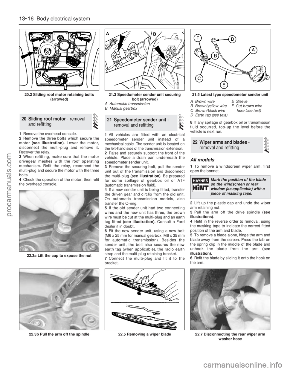
1Remove the overhead console.
2Remove the three bolts which secure the
motor (see illustration).Lower the motor,
disconnect the multi-plug and remove it.
Recover the relay.
3When refitting, make sure that the motor
drivegear meshes with the roof operating
mechanism. Refit the relay, reconnect the
multi-plug and secure the motor with the three
bolts.
4Check the operation of the motor, then refit
the overhead console.1All vehicles are fitted with an electrical
speedometer sender unit instead of a
mechanical cable. The sender unit is located on
the left-hand side of the transmission extension.
2Raise and securely support the front of the
vehicle. Place a drain pan underneath the
speedometer sender unit.
3Remove the securing bolt, pull the sender
unit out of the transmission and disconnect
the multi-plug (see illustration). Be prepared
for some spillage of gearbox oil or ATF
(automatic transmission fluid).
4If a new sender unit is being fitted, transfer
the driven gear and circlip from the old unit.
On automatic transmission models, also
transfer the O-ring.
5If the old sender unit had two connecting
wires and the new unit has three, the brown
wire must be cut at the multi-plug and an earth
tag fitted (see illustration).Consult a Ford
dealer if in doubt.
6Fit the new sender unit, using a new bolt
(M6 x 25 mm for manual gearbox, M6 x 35 mm
for automatic transmission). Besides the
sender unit, the bolt also secures the new
earth tag (when applicable), the radio earth
strap and the multi-plug retaining bracket.
7Connect the multi-plug and fit it to the
bracket.8If any spillage of gearbox oil or transmission
fluid occurred, top-up the level before the
vehicle is next run.
All models
1To remove a windscreen wiper arm, first
open the bonnet.
2Lift up the plastic cap and undo the wiper
arm retaining nut.
3Pull the arm off the drive spindle (see
illustrations).
4Refit in the reverse order to removal, using
the masking tape to indicate the correct fitted
position of the arm and blade.
5To remove a blade alone, hinge the arm and
blade away from the screen. Press the tab on
the spring clip in the middle of the blade and
unhook the blade from the arm (see
illustration).
6Refit the blade by sliding it onto the hook on
the arm.
22Wiper arms and blades -
removal and refitting
21Speedometer sender unit -
removal and refitting20Sliding roof motor - removal
and refitting
13•16Body electrical system
20.2 Sliding roof motor retaining bolts
(arrowed)
22.3b Pull the arm off the spindle
22.3a Lift the cap to expose the nut
22.5 Removing a wiper blade22.7 Disconnecting the rear wiper arm
washer hose
21.3 Speedometer sender unit securing
bolt (arrowed)
A Automatic transmission
B Manual gearbox21.5 Latest type speedometer sender unit
A Brown wire
B Brown/yellow wire
C Brown/black wire
D Earth tag (see text)E Sleeve
F Cut brown wire
here (see text)
Mark the position of the blade
on the windscreen or rear
window (as applicable) with a
piece of masking tape.
procarmanuals.com
Page 194 of 255
Estate
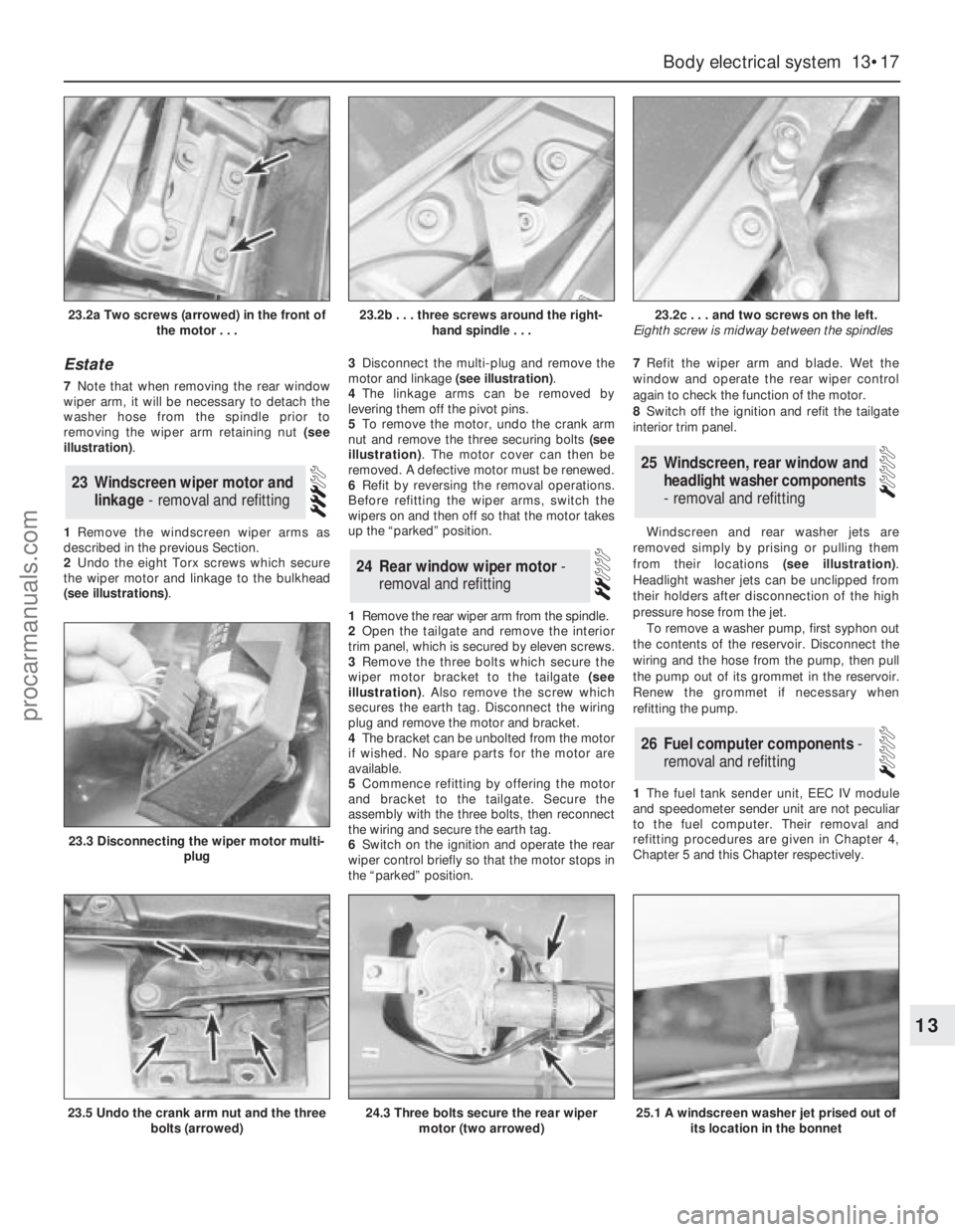
7Note that when removing the rear window
wiper arm, it will be necessary to detach the
washer hose from the spindle prior to
removing the wiper arm retaining nut (see
illustration).
1Remove the windscreen wiper arms as
described in the previous Section.
2Undo the eight Torx screws which secure
the wiper motor and linkage to the bulkhead
(see illustrations).3Disconnect the multi-plug and remove the
motor and linkage (see illustration).
4The linkage arms can be removed by
levering them off the pivot pins.
5To remove the motor, undo the crank arm
nut and remove the three securing bolts (see
illustration). The motor cover can then be
removed. A defective motor must be renewed.
6Refit by reversing the removal operations.
Before refitting the wiper arms, switch the
wipers on and then off so that the motor takes
up the “parked” position.
1Remove the rear wiper arm from the spindle.
2Open the tailgate and remove the interior
trim panel, which is secured by eleven screws.
3Remove the three bolts which secure the
wiper motor bracket to the tailgate (see
illustration). Also remove the screw which
secures the earth tag. Disconnect the wiring
plug and remove the motor and bracket.
4The bracket can be unbolted from the motor
if wished. No spare parts for the motor are
available.
5Commence refitting by offering the motor
and bracket to the tailgate. Secure the
assembly with the three bolts, then reconnect
the wiring and secure the earth tag.
6Switch on the ignition and operate the rear
wiper control briefly so that the motor stops in
the “parked” position.7Refit the wiper arm and blade. Wet the
window and operate the rear wiper control
again to check the function of the motor.
8Switch off the ignition and refit the tailgate
interior trim panel.
Windscreen and rear washer jets are
removed simply by prising or pulling them
from their locations (see illustration).
Headlight washer jets can be unclipped from
their holders after disconnection of the high
pressure hose from the jet.
To remove a washer pump, first syphon out
the contents of the reservoir. Disconnect the
wiring and the hose from the pump, then pull
the pump out of its grommet in the reservoir.
Renew the grommet if necessary when
refitting the pump.
1The fuel tank sender unit, EEC IV module
and speedometer sender unit are not peculiar
to the fuel computer. Their removal and
refitting procedures are given in Chapter 4,
Chapter 5 and this Chapter respectively.
26Fuel computer components -
removal and refitting
25Windscreen, rear window and
headlight washer components
- removal and refitting
24Rear window wiper motor -
removal and refitting
23Windscreen wiper motor and
linkage - removal and refitting
Body electrical system 13•17
13
23.2a Two screws (arrowed) in the front of
the motor . . .23.2b . . . three screws around the right-
hand spindle . . .23.2c . . . and two screws on the left.
Eighth screw is midway between the spindles
23.5 Undo the crank arm nut and the three
bolts (arrowed)
23.3 Disconnecting the wiper motor multi-
plug
24.3 Three bolts secure the rear wiper
motor (two arrowed)25.1 A windscreen washer jet prised out of
its location in the bonnet
procarmanuals.com
Page 196 of 255
17Refit by inserting the switch into the
grommet - use a new grommet if necessary -
and screwing on the retaining ring. Reconnect
the multi-plug and top-up the cooling system.
Washer fluid level switch
18Syphon the fluid out of the washer
reservoir until the level is below the switch.
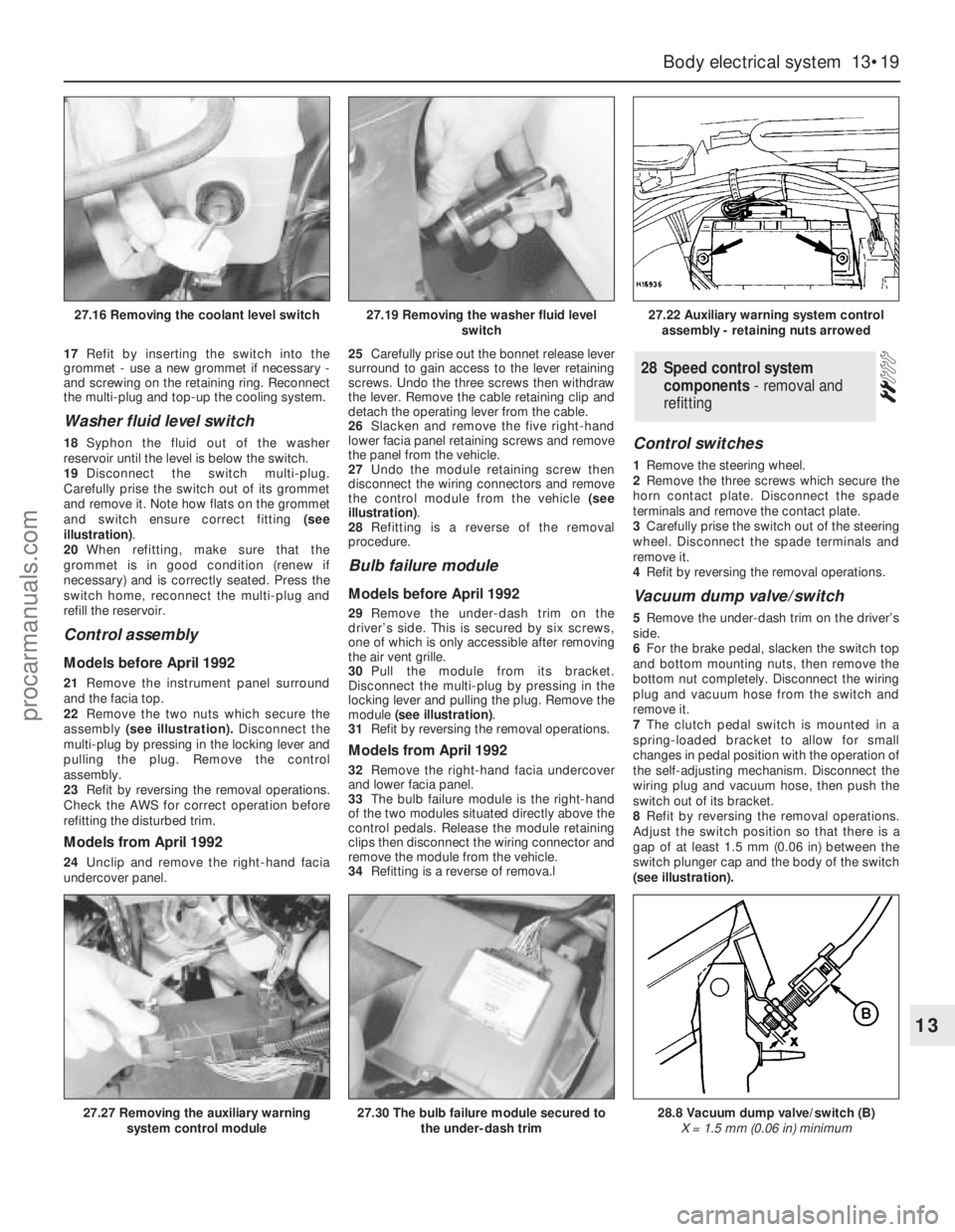
19Disconnect the switch multi-plug.
Carefully prise the switch out of its grommet
and remove it. Note how flats on the grommet
and switch ensure correct fitting (see
illustration).
20When refitting, make sure that the
grommet is in good condition (renew if
necessary) and is correctly seated. Press the
switch home, reconnect the multi-plug and
refill the reservoir.
Control assembly
Models before April 1992
21Remove the instrument panel surround
and the facia top.
22Remove the two nuts which secure the
assembly(see illustration).Disconnect the
multi-plug by pressing in the locking lever and
pulling the plug. Remove the control
assembly.
23Refit by reversing the removal operations.
Check the AWS for correct operation before
refitting the disturbed trim.
Models from April 1992
24Unclip and remove the right-hand facia
undercover panel.25Carefully prise out the bonnet release lever
surround to gain access to the lever retaining
screws. Undo the three screws then withdraw
the lever. Remove the cable retaining clip and
detach the operating lever from the cable.
26Slacken and remove the five right-hand
lower facia panel retaining screws and remove
the panel from the vehicle.
27Undo the module retaining screw then
disconnect the wiring connectors and remove
the control module from the vehicle (see
illustration).
28Refitting is a reverse of the removal
procedure.
Bulb failure module
Models before April 1992
29Remove the under-dash trim on the
driver’s side. This is secured by six screws,
one of which is only accessible after removing
the air vent grille.
30Pull the module from its bracket.
Disconnect the multi-plug by pressing in the
locking lever and pulling the plug. Remove the
module (see illustration).
31Refit by reversing the removal operations.
Models from April 1992
32Remove the right-hand facia undercover
and lower facia panel.
33The bulb failure module is the right-hand
of the two modules situated directly above the
control pedals. Release the module retaining
clips then disconnect the wiring connector and
remove the module from the vehicle.
34Refitting is a reverse of remova.l
Control switches
1Remove the steering wheel.
2Remove the three screws which secure the
horn contact plate. Disconnect the spade
terminals and remove the contact plate.
3Carefully prise the switch out of the steering
wheel. Disconnect the spade terminals and
remove it.
4Refit by reversing the removal operations.
Vacuum dump valve/switch
5Remove the under-dash trim on the driver’s
side.
6For the brake pedal, slacken the switch top
and bottom mounting nuts, then remove the
bottom nut completely. Disconnect the wiring
plug and vacuum hose from the switch and
remove it.
7The clutch pedal switch is mounted in a
spring-loaded bracket to allow for small
changes in pedal position with the operation of
the self-adjusting mechanism. Disconnect the
wiring plug and vacuum hose, then push the
switch out of its bracket.
8Refit by reversing the removal operations.
Adjust the switch position so that there is a
gap of at least 1.5 mm (0.06 in) between the
switch plunger cap and the body of the switch
(see illustration).
28Speed control system
components - removal and
refitting
Body electrical system 13•19
13
27.16 Removing the coolant level switch27.19 Removing the washer fluid level
switch27.22 Auxiliary warning system control
assembly - retaining nuts arrowed
27.27 Removing the auxiliary warning
system control module27.30 The bulb failure module secured to
the under-dash trim28.8 Vacuum dump valve/switch (B)
X = 1.5 mm (0.06 in) minimum
procarmanuals.com
Page 197 of 255
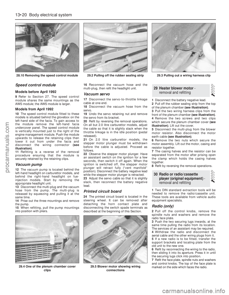
Speed control module
Models before April 1992
9Refer to Section 27. The speed control
module shares the same mountings as the
AWS module; the AWS module is larger.
Models from April 1992
10The speed control module fitted to these
models is situated behind the glovebox on the
left-hand side of the facia. To gain access to
the module remove the left-hand facia
undercover panel. The speed control module
is vertically mounted just to the right of the
engine management module. Push the module
upwards to release the retaining clips then
lower it out from under the facia and
disconnect the wiring connector (see
illustration).
11Refitting is a reverse of the removal
procedure ensuring that the module is
securely retained by the retaining clips.
Vacuum pump
12The vacuum pump is located behind the
left-hand headlight on carburettor models, and
behind the right-hand headlight on fue-
injection models. Start by removing the
appropriate headlight unit.
13Disconnect the multi-plug and the vacuum
hose from the pump. The multi-plug is
released by squeezing and pulling it at the
same time.
14Prise out the three mountings and remove
the pump.
15When refitting, pull the pump mountings
into position with pliers. 16Reconnect the vacuum hose and the
multi-plug, then refit the headlight unit.
Vacuum servo
17Disconnect the servo-to-throttle linkage
cable at one end.
18Disconnect the vacuum hose from the
servo.
19Undo the servo retaining nut and remove
the servo from its bracket.
20Refit by reversing the removal operations.
On all but 2.0 litre carburettor models, adjust
the cable so that it is slightly slack when the
throttle linkage is in the idle position (pedal
released).
21On 2.0 litre carburettor models, the
stepper motor plunger must be withdrawn
before the cable is adjusted. Proceed as
follows.
22Observe the stepper motor plunger. Have
an assistant switch on the ignition for a few
seconds, then switch it off again. When the
ignition is switched off, the stepper motor
plunger will retract fully (“vent manifold”
position). Disconnect the battery negative lead
while the stepper motor plunger is retracted.
23Adjust the servo cable so that it is slightly
slack, then reconnect the battery negative
lead.
Printed circuit board
24The printed circuit board is located in the
steering wheel. It can be removed after
detaching the horn contact plate and
disconnecting the switch spade terminals as
described at the beginning of this Section.1Disconnect the battery negative lead.
2Pull off the rubber sealing strip from the top
of the plenum chamber (see illustration).
3Pull the two wiring harness clips from the
front of the plenum chamber (see illustration).
4Remove the two screws and two clips
which secure the plenum chamber cover (see
illustration). Lift out the cover.
5Disconnect the multi-plug from the blower
motor resistor. Also disconnect the motor
earth cable (see illustration).
6Remove the two nuts which secure the
motor assembly. Lift out the motor, casing and
resistor together.
7The casing halves and the resistor can be
separated from the motor after prising open
the clamp which holds the casing halves
together.
8Refit by reversing the removal operations.
1Two DIN standard extraction tools will be
needed to remove the radio/cassette unit.
These tools are available from vehicle audio
equipment specialists.
Radio (only)
2Pull off the control knobs, remove the
spindle nuts and washers and remove the
radio face plate.
3Push the two securing lugs inwards, at the
same time pulling the radio from its location.
The services of an assistant may be required.
4Withdraw the radio and disconnect the
aerial cable and the other wiring plugs from it.
5If a new radio is to be fitted, transfer the
support brackets and locating plate from the
old unit to the new one.
6Refit by reconnecting the wiring to the radio,
then sliding it into its aperture. Press it in until
the securing lugs click into position.
7Refit the face plate, spindle nuts and washers
and control knobs. The top of the face plate is
marked on the side which faces the radio.
30Radio or radio/cassette
player (original equipment) -
removal and refitting
29Heater blower motor -
removal and refitting
13•20Body electrical system
28.10 Removing the speed control module
29.4 One of the plenum chamber cover
clips29.5 Blower motor showing wiring
connections
29.2 Pulling off the rubber sealing strip29.3 Pulling out a wiring harness clip
procarmanuals.com
Page 201 of 255
WD•0
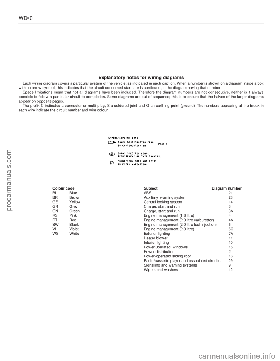
Explanatory notes for wiring diagrams
Each wiring diagram covers a particular system of the vehicle; as indicated in each caption. When a number is shown on a diagram inside a box
with an arrow symbol, this indicates that the circuit concerned starts, or is continued, in the diagram having that number.
Space limitations mean that not all diagrams have been included. Therefore the diagram numbers are not consecutive, neither is it always
possible to follow a particular circuit to completion. Some diagrams are out of sequence; this is to ensure that the halves of the larger diagrams
appear on opposite pages.
The prefix C indicates a connector or multi-plug, S a soldered joint and G an earthing point (ground). The numbers appearing at the break in
each wire indicate the circuit number and wire colour.
Colour code
BLBlue
BRBrown
GEYellow
GRGrey
GNGreen
RSPink
RT Red
SWBlack
VIViolet
WSWhiteSubjectDiagram number
ABS21
Auxiliary warning system23
Central locking system14
Charge, start and run3
Charge, start and run3A
Engine management (1.8 litre)4
Engine management (2.0 litre carburettor)4A
Engine management (2.0 litre fuel-injection)5
Engine management (2.8 litre)5C
Exterior lighting7A
Heater blower11
Interior lighting10
Power 0perated windows15
Power distribution2
Power-operated sliding roof16
Radio/cassette player and associated circuits29
Signalling and warning systems9
Wipers and washers12
procarmanuals.com