brake rotor FORD GRANADA 1985 Service Repair Manual
[x] Cancel search | Manufacturer: FORD, Model Year: 1985, Model line: GRANADA, Model: FORD GRANADA 1985Pages: 255, PDF Size: 14.98 MB
Page 3 of 255
1•2
Every 12 000 miles (20 000 km) or
12 months – whichever comes sooner
m mCheck operation of latches, check straps and locks; lubricate if
necessary (Section 19)
m mCheck condition and tension of auxiliary drivebelt(s); adjust or
renew as necessary (Section 21)
m mCheck tightness of battery terminals, clean and neutralise
corrosion if necessary (Section 22)
m mCheck engine valve clearances (Section 23) m
mCheck tightness of inlet manifold bolts (V6 only) (Section 24) m
mRenew spark plugs (Section 20) m
mClean air conditioning condenser fins (when applicable)
(Section 25)
m mCheck air conditioning refrigerant charge (when applicable)
(Section 26)
m mCheck manual gearbox oil level (Section 18) m
mCheck final drive oil level (Section 27) m
mLubricate automatic transmission selector/kickdown linkage
(Section 28)
m mCheck security and condition of steering and suspension
components, gaiters and boots (Section 29)
m mCheck condition and security of driveshaft joints (Section 30) m
mInspect underbody and panels for corrosion or other damage
(Section 31)
m mInspect brake pipes and hoses (Section 32) m
mClean idle speed control linkage at throttle (when applicable)
(Section 33)
m mRoad test and check operation of ABS (Section 34)m
mCheck automatic transmission fluid level (engine hot)
(Section 17)
m mCheck engine for satisfactory hot starting (Section 37)m
mCheck that automatic choke is fully off with engine hot (not fuel-
injection models) (Section 36)
m mCheck power steering fluid level (when applicable) (Section 35)
Every 24 000 miles (40 000 km) or
2 years - whichever comes sooner
m
mRenew air cleaner element (Section 38) m
mClean and inspect distributor cap, rotor arm, HT leads and coil
tower (Section 39)
m mAdjust automatic transmission brake bands (Section 40)m
mRenew fuel filter (fuel-injection models only) (Section 41) m
mRenew crankcase ventilation vent valve (carburettor models)
(Section 42)
Every 36 000 miles (60 000 km) or
3 years - whichever comes sooner
m
mRenew brake hydraulic system seals and hoses if necessary
(Section 43)
m mRenew brake hydraulic fluid (Section 44) m
mRenew camshaft drivebelt on SOHC models - recommended as
a precautionary measure (Section 45)
Every 2 years - regardless of mileage
m
mRenew coolant (Section 46)
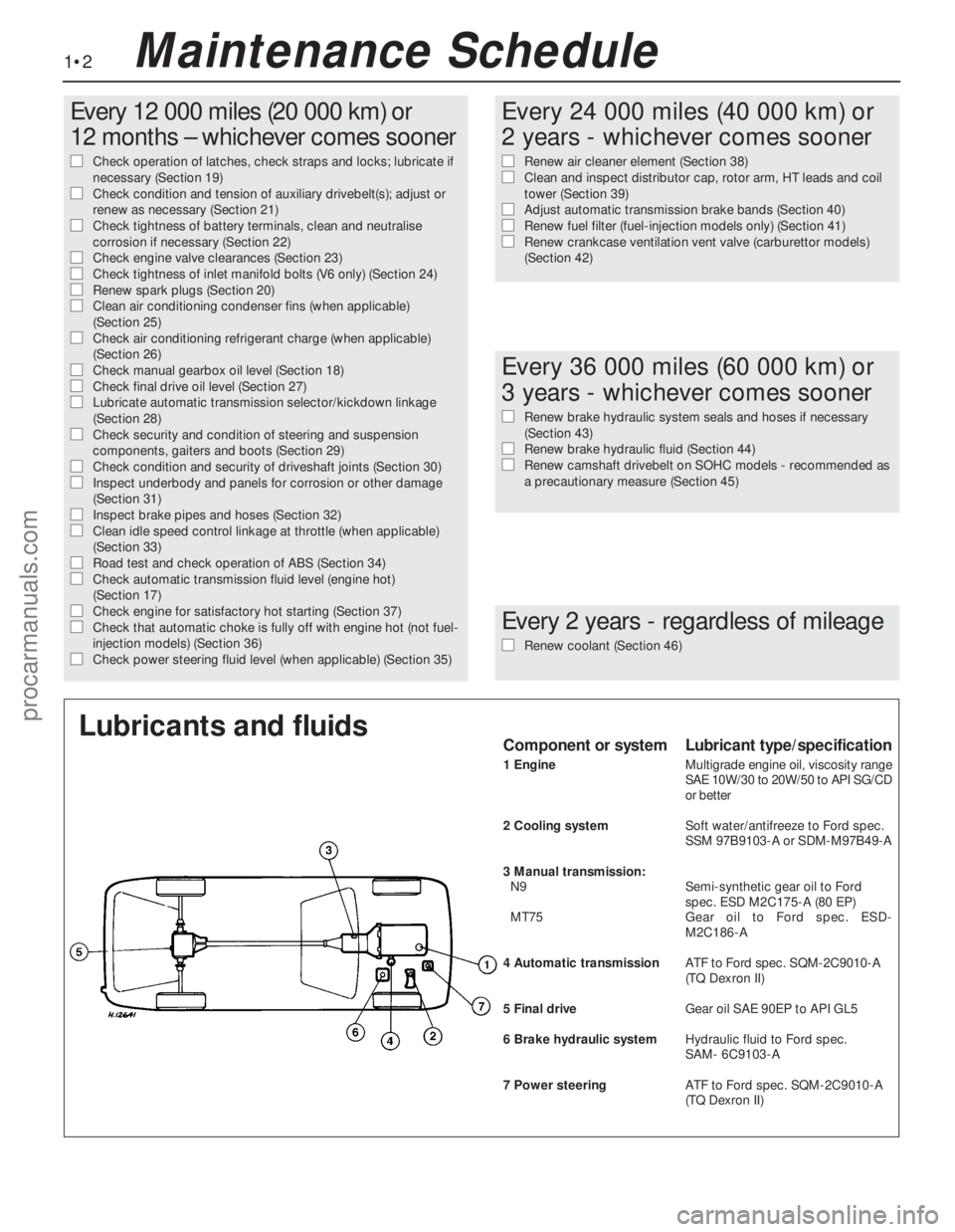
Lubricants and fluidsComponent or systemLubricant type/specification
1 EngineMultigrade engine oil, viscosity range
SAE 10W/30 to 20W/50 to API SG/CD
or better
2 Cooling systemSoft water/antifreeze to Ford spec.
SSM 97B9103-A or SDM-M97B49-A
3 Manual transmission:
N9Semi-synthetic gear oil to Ford
spec. ESD M2C175-A (80 EP)
MT75Gear oil to Ford spec. ESD-
M2C186-A
4 Automatic transmissionATF to Ford spec. SQM-2C9010-A
(TQ Dexron II)
5 Final driveGear oil SAE 90EP to APIGL5
6 Brake hydraulic systemHydraulic fluid to Ford spec.
SAM- 6C9103-A
7 Power steeringATFto Ford spec. SQM-2C9010-A
(TQDexron II)
Maintenance Schedule
procarmanuals.com
Page 20 of 255
the previous sub Section.
27Refitting is a reversal of removal, ensuring
that the rotor arm is pushed fully home on the
rotor shaft. Make sure that the HT leads are
fitted to their correct cylinders. Note that the
rotor arm will only fit in one position.
Note: A brake band torque wrench - Ford tool
No 17-005, or equivalent - will be required for
this job.
1Raise and support the front of the vehicle.
2Disconnect the downshift (kickdown) cable
from the transmission when so equipped.
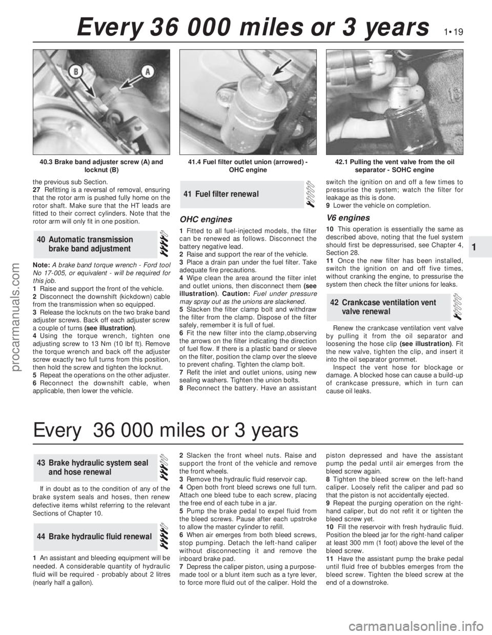
3Release the locknuts on the two brake band
adjuster screws. Back off each adjuster screw
a couple of turns (see illustration).
4Using the torque wrench, tighten one
adjusting screw to 13 Nm (10 lbf ft). Remove
the torque wrench and back off the adjuster
screw exactly two full turns from this position,
then hold the screw and tighten the locknut.
5Repeat the operations on the other adjuster.
6Reconnect the downshift cable, when
applicable, then lower the vehicle.
OHC engines
1Fitted to all fuel-injected models, the filter
can be renewed as follows. Disconnect the
battery negative lead.
2Raise and support the rear of the vehicle.
3Place a drain pan under the fuel filter. Take
adequate fire precautions.
4Wipe clean the area around the filter inlet
and outlet unions, then disconnect them (see
illustration). Caution: Fuel under pressure
may spray out as the unions are slackened.
5Slacken the filter clamp bolt and withdraw
the filter from the clamp. Dispose of the filter
safely, remember it is full of fuel.
6Fit the new filter into the clamp,observing
the arrows on the filter indicating the direction
of fuel flow. If there is a plastic band or sleeve
on the filter, position the clamp over the sleeve
to prevent chafing. Tighten the clamp bolt.
7Refit the inlet and outlet unions, using new
sealing washers. Tighten the union bolts.
8Reconnect the battery. Have an assistantswitch the ignition on and off a few times to
pressurise the system; watch the filter for
leakage as this is done.
9Lower the vehicle on completion.
V6 engines
10This operation is essentially the same as
described above, noting that the fuel system
should first be depressurised, see Chapter 4,
Section 28.
11Once the new filter has been installed,
switch the ignition on and off five times,
without cranking the engine, to pressurise the
system then check the filter unions for leaks.
Renew the crankcase ventilation vent valve
by pulling it from the oil separator and
loosening the hose clip (see illustration). Fit
the new valve, tighten the clip, and insert it
into the oil separator grommet.
Inspect the vent hose for blockage or
damage. A blocked hose can cause a build-up
of crankcase pressure, which in turn can
cause oil leaks.
42Crankcase ventilation vent
valve renewal
41Fuel filter renewal
40Automatic transmission
brake band adjustment
1•19
1
Every 36 000 miles or 3 years
41.4 Fuel filter outlet union (arrowed) -
OHC engine42.1 Pulling the vent valve from the oil
separator - SOHC engine40.3 Brake band adjuster screw (A) and
locknut (B)
If in doubt as to the condition of any of the
brake system seals and hoses, then renew
defective items whilst referring to the relevant
Sections of Chapter 10.
1An assistant andbleeding equipment will be
needed. A considerable quantity of hydraulic
fluid will be required - probably about 2 litres
(nearly half a gallon).2Slacken the front wheel nuts. Raise and
support the front of the vehicle andremove
the front wheels.
3Remove the hydraulic fluid reservoir cap.
4Open both front bleed screws one full turn.
Attach one bleed tube to each screw, placing
the free end of each tube in a jar.
5Pump the brake pedal to expel fluid from
the bleed screws. Pause after each upstroke
to allow the master cylinder to refill.
6When air emerges from both bleed screws,
stop pumping. Detach the left-hand caliper
without disconnecting it and remove the
inboard brake pad.
7Depress the caliper piston, using a purpose-
made tool or a blunt item such as a tyre lever,
to force more fluid out of the caliper. Hold thepiston depressed and have the assistant
pump the pedal until air emerges from the
bleed screw again.
8Tighten the bleed screw on the left-hand
caliper. Loosely refit the caliper and pad so
that the piston is not accidentally ejected.
9Repeat the purging operation on the right-
hand caliper, but do not refit it or tighten the
bleed screw yet.
10Fill the reservoir with fresh hydraulic fluid.
Position the bleed jar for the right-hand caliper
at least 300 mm (1 foot) above the level of the
bleed screw.
11Have the assistant pump the brake pedal
until fluid free of bubbles emerges from the
bleed screw. Tighten the bleed screw at the
end of a downstroke.
44Brake hydraulic fluid renewal
43Brake hydraulic system seal
and hose renewal
Every 36 000 miles or 3 years
procarmanuals.com
Page 54 of 255
6Disconnect the breather hose from the
camshaft cover, and unbolt the hose bracket
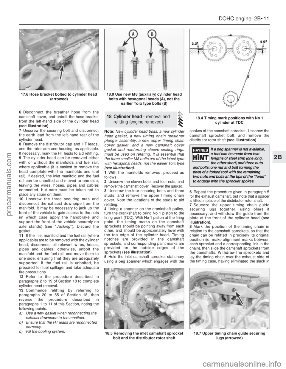
from the left-hand side of the cylinder head
(see illustration).
7Unscrew the securing bolt and disconnect
the earth lead from the left-hand rear of the
cylinder head.
8Remove the distributor cap and HT leads,
and the rotor arm and housing, as applicable.
If necessary, mark the HT leads to aid refitting.
9The cylinder head can be removed either
with or without the manifolds and fuel rail,
where applicable (it is easiest to remove the
head complete with the manifolds and fuel
rail). If desired, the inlet manifold and the fuel
rail can be unbolted and moved to one side,
leaving the wires, hoses, pipes and cables
connected, but care must be taken not to
place any strain on them.
10Unscrew the three securing nuts and
disconnect the exhaust downpipe from the
manifold. It may be necessary to jack up the
front of the vehicle to gain access to the nuts
(in which case apply the handbrake and
support the front of the vehicle securely on
axle stands) (see “Jacking”). Discard the
gasket.
11If the inlet manifold and the fuel rail (where
applicable) are to be removed with the cylinder
head, disconnect all relevant wires, hoses,
pipes and cables, otherwise, unbolt the
manifold and the fuel rail, and move them to
one side, ensuring that they are adequately
supported. If the fuel rail is unbolted, be
prepared for fuel spillage, and take adequate
fire precautions.
12Refer to the procedure described in
paragraphs 2 to 19 of Section 18 to complete
cylinder head removal.
13Commence refitting by referring to
paragraphs 20 to 55 of Section 18, then
reverse the procedure described in
paragraphs 1 to 11 of this Section, noting the
following points.
a)Use a new gasket when reconnecting the
exhaust downpipe to the manifold.
b)Ensure that the HT leads are reconnected
correctly.
c)Fill the cooling system.Note: New cylinder head bolts, a new cylinder
head gasket, a new timing chain tensioner
plunger assembly, a new upper timing chain
cover gasket, and a new camshaft cover
gasket and reinforcing sleeve sealing rings
must be used on refitting. It is essential that
the three smaller M8 bolts are of the latest type
with hexagonal heads, not the earlier Torx type
(see illustration).
1With the manifolds removed, proceed as
follows.
2Unscrew the eleven bolts and four nuts, and
remove the camshaft cover. Recover the gasket.
3Unscrew the four securing bolts and three
studs, and remove the upper timing chain
cover. Note the locations of the studs to aid
refitting.
4Using a spanner on the crankshaft pulley,
turn the crankshaft to bring No 1 piston to the
firing point (TDC). With No 1 piston at the firing
point, the timing marks on the camshaft
sprockets should be pointing away from each
other, and should be approximately level with
the top edge of the cylinder head. Timing
notches are provided in the camshaft
sprockets, and corresponding paint marks are
provided on the outside edges of the
sprockets (see illustration).
5Hold the inlet camshaft sprocket stationary
using a peg spanner which engages with thespokes of the camshaft sprocket. Unscrew the
camshaft sprocket bolt, and remove the
distributor rotor shaft (see illustration).
6Repeat the procedure given in paragraph 5
for the exhaust camshaft, but note that a spacer
is fitted in place of the distributor rotor shaft.
7Squeeze the upper timing chain guide
securing lugs together, using pliers if
necessary, and withdraw the guide from the
plate at the front of the cylinder head (see
illustration).
8Mark the position of the timing chain in
relation to the camshaft sprockets, so that the
chain can be refitted in precisely its original
position (ie, make alignment marks between
each sprocket and a corresponding link in the
chain), then slide the camshaft sprockets from
the camshafts. Withdraw the sprockets and
lay the timing chain over the exhaust side of
the timing case, having eliminated the slack in18Cylinder head - removal and
refitting (engine removed)
DOHCengine 2B•11
2B
17.6 Hose bracket bolted to cylinder head
(arrowed)18.0 Use new M8 (auxiliary) cylinder head
bolts with hexagonal heads (A), not the
earlier Torx type bolts (B)
18.4 Timing mark positions with No 1
cylinder at TDC
18.5 Removing the inlet camshaft sprocket
bolt and the distributor rotor shaft18.7 Upper timing chain guide securing
lugs (arrowed)
If a peg spanner is not available,
a tool can be made from two
lengths of steel strip (one long,
the other short) and three nuts
and bolts; one nut and bolt forming the
pivot of a forked tool with the remaining
two nuts and bolts at the tips of the “forks”
to engage with the sprocket spokes.
procarmanuals.com
Page 58 of 255
d)Disconnect the breather hose from the
camshaft cover.
e)Remove the distributor cap and HT leads,
and the rotor arm and housing. If
necessary, mark the HT leads to aid
refitting.
2Proceed as described in paragraphs 2 to 15
inclusive of Section 18.
3Examine the surfaces of the camshaft
journals and lobes and the contact surfaces of
the cam followers for wear. If wear is
excessive, considerable noise would have
been noticed from the top of the engine when
running, and new camshafts and followers
must be fitted. It is unlikely that this level of
wear will occur unless a considerable mileage
has been covered. Note that the cam followers
cannot be dismantled for renewal of individual
components.
4Check the camshaft bearing surfaces in the
cylinder head and the bearing caps for wear. If
excessive wear is evident, the only course of
action available is to renew the cylinder head
complete with bearing caps.
5Check the cam follower bores in the
cylinder head for wear. If excessive wear is
evident, the cylinder head must be renewed.
6Check the cam follower oil grooves and the
oil ports in the cylinder head for obstructions.
7Refit the cam followers and the camshafts as
described in paragraphs 27 to 55 of Section 18.
8If the engine is in the vehicle, reverse the
operations given in paragraph 1.
Refer to Part A, Section 15 of this Chapter,
noting the following points.
a)If the engine is in the car, refer to Chapter
6 when removing and refitting the clutch,
where applicable.
b)The flywheel/driveplate securing bolts
must be renewed on refitting; the new
bolts are supplied ready-coated with
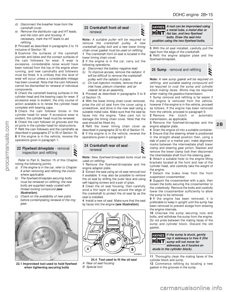
thread-locking compound (see
illustration).
c)Check on the availability of new parts
before contemplating renewal of the ring
gear.Note: A suitable puller will be required to
remove the crankshaft pulley. A new
crankshaft pulley bolt and a new lower timing
chain cover gasket must be used on refitting.
1The crankshaft front oil seal is located in the
lower timing chain cover.
2If the engine is in the car, carry out the
following operations.
a)Disconnect the battery negative lead.
b)To improve access, remove the radiator. It
will be difficult to remove the crankshaft
pulley with the radiator in place.
c)On fuel-injection models, remove the air
inlet hose, plenum chamber, and air
cleaner lid as an assembly.
3Proceed as described in paragraphs 3 to 8
of Section 15.
4With the lower timing chain cover removed,
prise the old oil seal from the cover using a
screwdriver, and drive in the new seal using a
suitable metal tube. Make sure that the seal lip
faces into the engine. Take care not to
damage the timing chain cover. Note that the
seal should be fitted dry.
5Refit the lower timing chain cover as
described in paragraphs 32 to 40 of Section 15.
6If the engine is in the vehicle, reverse the
operations given in paragraph 2.
Note: New flywheel/driveplate bolts must be
used on refitting.
1Remove the flywheel/driveplate and the
engine adapter plate.
2Extract the seal using an oil seal removal tool
if available. It may also be possible to remove
the oil seal by drilling the outer face and using
self-tapping screws and a pair of grips.
3Clean the oil seal housing, then carefully
wind a thin layer of tape around the edge of
the crankshaft to protect the oil seal lip as the
seal is installed.
4Install a new oil seal. Make sure that the seal
lip faces into the engine (see illustration).5With the oil seal installed, carefully pull the
tape from the edge of the crankshaft.
6Refit the engine adapter plate and the
flywheel/driveplate.
Note: A new sump gasket will be required on
refitting, and suitable sealing compound will
be required to coat the sump and cylinder
block mating faces. Shims may be required
when mating the gearbox/transmission.
1Sump removal and refitting is far easier if
the engine is removed from the vehicle,
however if the engine is in the vehicle, proceed
as follows. If the engine has been removed
from the vehicle, proceed to paragraph 9.
2Remove the clutch or automatic
transmission, as applicable.
3Remove the flywheel/driveplate and the
engine adapter plate.
4Drain the engine oil into a suitable container.
5Ensure that the steering wheel is positioned
in the straight-ahead position then, using a
dab of paint or a marker pen, make alignment
marks between the intermediate shaft lower
clamp and steering gear pinion. Slacken and
remove the lower clamp bolt then disconnect
the intermediate shaft from the steering gear.
6Attach a suitable hoist to the engine lifting
brackets located at the front and rear of the
cylinder head, and carefully take the weight of
the engine.
7Detach the brake lines from the front
suspension crossmember.
8Support the crossmember with a jack, then
loosen the bolts securing the crossmember to
the underbody. Remove the bolts and carefully
lower the crossmember sufficiently to allow
the sump to be removed.
9If the engine has been removed, it is
preferable to keep it upright until the sump has
been removed to prevent sludge from entering
the engine internals.
10Unscrew the sump securing nuts and
bolts, and withdraw the sump from the engine.
Do not prise between the mating faces of the
sump and cylinder block. Discard the old
gasket.
11Thoroughly clean the mating faces of the
cylinder block and sump.
12Commence refitting by locating a new
gasket in the grooves in the sump.
25Sump - removal and refitting
24Crankshaft rear oil seal -
renewal
23Crankshaft front oil seal -
renewal
22Flywheel/driveplate - removal
inspection and refitting
DOHCengine 2B•15
2B
22.1 Improvised tool used to hold flywheel
when tightening securing bolts
24.4 Tool used to fit the oil seal
A Rear oil seal housing
B Special tool
A tool can be improvised using
a metal tube, a metal disc or
flat bar, and two flywheel
bolts.Draw the seal into
position using the two flywheel bolts.
If the sump is stuck, gently
tap it sideways to free it (the
sump will not move far
sideways, as it locates on
studs in the cylinder block).
procarmanuals.com
Page 71 of 255
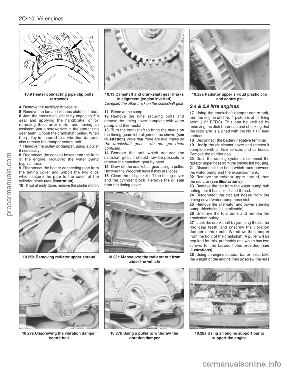
4Remove the auxiliary drivebelts.
5Remove the fan and viscous clutch if fitted).
6Jam the crankshaft, either by engaging 5th
gear and applying the handbrake, or by
removing the starter motor and having an
assistant jam a screwdriver in the starter ring
gear teeth. Unbolt the crankshaft pulley. When
the pulley is secured to a vibration damper,
also remove the damper central bolt.
7Remove the pulley or damper, using a puller
if necessary.
8Disconnect the coolant hoses from the front
of the engine, including the water pump
bypass hose.
9Disconnect the heater connecting pipe from
the timing cover and unbolt the two clips
which secure the pipe to the cover of the
cylinder block (see illustration).
10If not already done, remove the starter motor.11Remove the sump.
12Remove the nine securing bolts and
remove the timing cover complete with water
pump and thermostat.
13Turn the crankshaft to bring the marks on
the timing gears into alignment as shown (see
illustration). Note that there are two marks on
the crankshaft gear - do not get them
confused.
14Remove the bolt which secures the
camshaft gear. It should now be possible to
remove the camshaft gear by hand.
15Draw off the crankshaft gear using a puller.
Recover the Woodruff keys if they are loose.
16Clean the old gasket off the timing cover
and the cylinder block. Remove the oil seal
from the timing cover.2.4 & 2.9 litre engines
17Using the crankshaft damper centre bolt,
turn the engine until No 1 piston is at its firing
point (12°BTDC). This can be verified by
removing the distributor cap and checking that
the rotor arm is aligned with the No 1 HT lead
contact.
18Disconnect the battery negative terminal.
19Unclip the air cleaner cover and remove it
complete with air flow sensors and air hoses.
Remove the oil filler cap.
20Drain the cooling system, disconnect the
radiator upper hose from the thermostat housing.
21Disconnect the hose which runs between
the water pump and the expansion tank.
22Remove the radiator upper shroud, then
the radiator (see illustrations).
23Remove the fan from the water pump hub
noting that it has a left-hand thread.
24Disconnect the coolant hoses from the
timing cover/water pump hose stubs.
25Remove the alternator and power steering
pump drivebelts (as applicable)
26Unscrew the four bolts and remove the
crankshaft pulley.
27Lock the crankshaft by jamming the starter
ring gear teeth, and unscrew the vibration
damper centre bolt. Withdraw the damper
from the front of the crankshaft. A puller will be
required for this, preferably one which has two
screws for the tapped holes provided (see
illustrations).
28Using an engine support bar or hoist, take
the weight of the engine then unscrew the nuts
2C•10V6 engines
10.9 Heater connecting pipe clip bolts
(arrowed)
10.27a Unscrewing the vibration damper
centre bolt
10.22b Removing radiator upper shroud10.22c Manoeuvre the radiator out from
under the vehicle
10.27b Using a puller to withdraw the
vibration damper10.28a Using an engine support bar to
support the engine
10.13 Camshaft and crankshaft gear marks
in alignment (engine inverted)
Disregard the other mark on the crankshaft gear10.22a Radiator upper shroud plastic clip
and centre pin
procarmanuals.com
Page 151 of 255
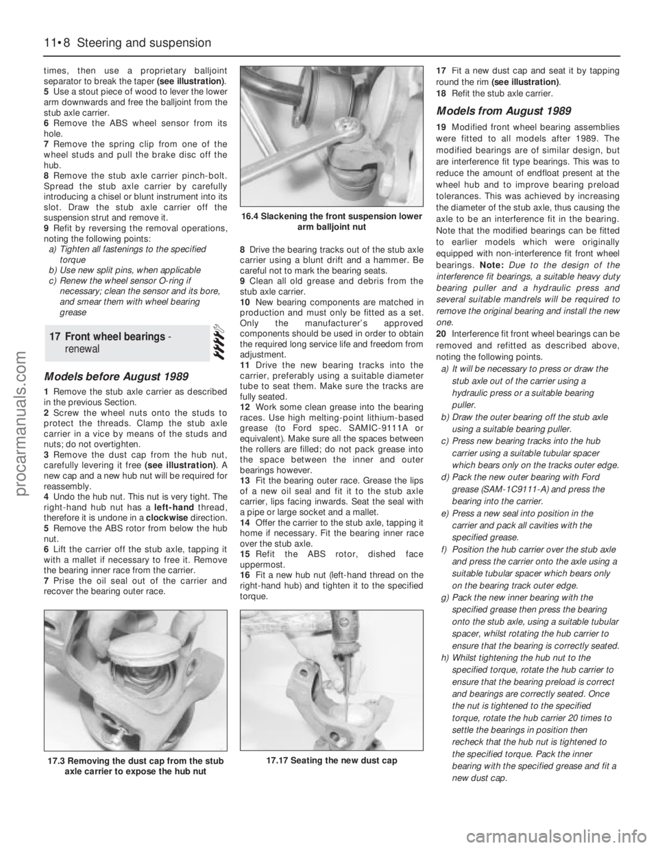
times, then use a proprietary balljoint
separator to break the taper (see illustration).
5Use a stout piece of wood to lever the lower
arm downwards and free the balljoint from the
stub axle carrier.
6Remove the ABS wheel sensor from its
hole.
7Remove the spring clip from one of the
wheel studs and pull the brake disc off the
hub.
8Remove the stub axle carrier pinch-bolt.
Spread the stub axle carrier by carefully
introducing a chisel or blunt instrument into its
slot. Draw the stub axle carrier off the
suspension strut and remove it.
9Refit by reversing the removal operations,
noting the following points:
a)Tighten all fastenings to the specified
torque
b)Use new split pins, when applicable
c)Renew the wheel sensor O-ring if
necessary; clean the sensor and its bore,
and smear them with wheel bearing
grease
Models before August 1989
1Remove the stub axle carrier as described
in the previous Section.
2Screw the wheel nuts onto the studs to
protect the threads. Clamp the stub axle
carrier in a vice by means of the studs and
nuts; do not overtighten.
3Remove the dust cap from the hub nut,
carefully levering it free (see illustration). A
new cap and a new hub nut will be required for
reassembly.
4Undo the hub nut. This nut is very tight. The
right-hand hub nut has a left-handthread,
therefore it is undone in a clockwisedirection.
5Remove the ABS rotor from below the hub
nut.
6Lift the carrier off the stub axle, tapping it
with a mallet if necessary to free it. Remove
the bearing inner race from the carrier.
7Prise the oil seal out of the carrier and
recover the bearing outer race.8Drive the bearing tracks out of the stub axle
carrier using a blunt drift and a hammer. Be
careful not to mark the bearing seats.
9Clean all old grease and debris from the
stub axle carrier.
10New bearing components are matched in
production and must only be fitted as a set.
Only the manufacturer’s approved
components should be used in order to obtain
the required long service life and freedom from
adjustment.
11Drive the new bearing tracks into the
carrier, preferably using a suitable diameter
tube to seat them. Make sure the tracks are
fully seated.
12Work some clean grease into the bearing
races. Use high melting-point lithium-based
grease (to Ford spec. SAMIC-9111A or
equivalent). Make sure all the spaces between
the rollers are filled; do not pack grease into
the space between the inner and outer
bearings however.
13Fit the bearing outer race. Grease the lips
of a new oil seal and fit it to the stub axle
carrier, lips facing inwards. Seat the seal with
a pipe or large socket and a mallet.
14Offer the carrier to the stub axle, tapping it
home if necessary. Fit the bearing inner race
over the stub axle.
15Refit the ABS rotor, dished face
uppermost.
16Fit a new hub nut (left-hand thread on the
right-hand hub) and tighten it to the specified
torque.17Fit a new dust cap and seat it by tapping
round the rim (see illustration).
18Refit the stub axle carrier.
Models from August 1989
19Modified front wheel bearing assemblies
were fitted to all models after 1989. The
modified bearings are of similar design, but
are interference fit type bearings. This was to
reduce the amount of endfloat present at the
wheel hub and to improve bearing preload
tolerances. This was achieved by increasing
the diameter of the stub axle, thus causing the
axle to be an interference fit in the bearing.
Note that the modified bearings can be fitted
to earlier models which were originally
equipped with non-interference fit front wheel
bearings. Note: Due to the design of the
interference fit bearings, a suitable heavy duty
bearing puller and a hydraulic press and
several suitable mandrels will be required to
remove the originalbearing and install the new
one.
20Interference fit front wheel bearings can be
removed and refitted as described above,
noting the following points.
a)It will be necessary to press or draw the
stub axle out of the carrier using a
hydraulic press or a suitable bearing
puller.
b)Draw the outer bearing off the stub axle
using a suitable bearing puller.
c)Press new bearing tracks into the hub
carrier using a suitable tubular spacer
which bears only on the tracks outer edge.
d)Pack the new outer bearing with Ford
grease (SAM-1C9111-A) and press the
bearing into the carrier.
e)Press a new seal into position in the
carrier and pack all cavities with the
specified grease.
f)Position the hub carrier over the stub axle
and press the carrier onto the axle using a
suitable tubular spacer which bears only
on the bearing track outer edge.
g)Pack the new inner bearing with the
specified grease then press the bearing
onto the stub axle, using a suitable tubular
spacer, whilst rotating the hub carrier to
ensure that the bearing is correctly seated.
h)Whilst tightening the hub nut to the
specified torque, rotate the hub carrier to
ensure that the bearing preload is correct
and bearings are correctly seated. Once
the nut is tightened to the specified
torque, rotate the hub carrier 20 times to
settle the bearings in position then
recheck that the hub nut is tightened to
the specified torque. Pack the inner
bearing with the specified grease and fit a
new dust cap.
17Front wheel bearings -
renewal
11•8Steering and suspension
16.4 Slackening the front suspension lower
arm balljoint nut
17.17 Seating the new dust cap17.3 Removing the dust cap from the stub
axle carrier to expose the hub nut
procarmanuals.com
Page 249 of 255
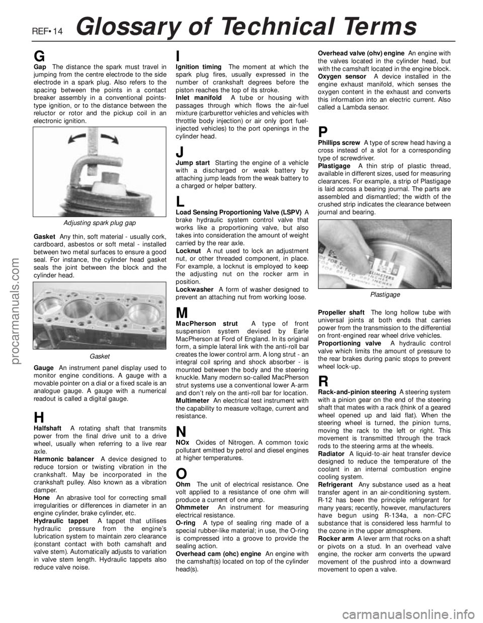
REF•14Glossary of Technical Terms
GGapThe distance the spark must travel in
jumping from the centre electrode to the side
electrode in a spark plug. Also refers to the
spacing between the points in a contact
breaker assembly in a conventional points-
type ignition, or to the distance between the
reluctor or rotor and the pickup coil in an
electronic ignition.
GasketAny thin, soft material - usually cork,
cardboard, asbestos or soft metal - installed
between two metal surfaces to ensure a good
seal. For instance, the cylinder head gasket
seals the joint between the block and the
cylinder head.
GaugeAn instrument panel display used to
monitor engine conditions. A gauge with a
movable pointer on a dial or a fixed scale is an
analogue gauge. A gauge with a numerical
readout is called a digital gauge.
HHalfshaftA rotating shaft that transmits
power from the final drive unit to a drive
wheel, usually when referring to a live rear
axle.
Harmonic balancerA device designed to
reduce torsion or twisting vibration in the
crankshaft. May be incorporated in the
crankshaft pulley. Also known as a vibration
damper.
HoneAn abrasive tool for correcting small
irregularities or differences in diameter in an
engine cylinder, brake cylinder, etc.
Hydraulic tappetA tappet that utilises
hydraulic pressure from the engine’s
lubrication system to maintain zero clearance
(constant contact with both camshaft and
valve stem). Automatically adjusts to variation
in valve stem length. Hydraulic tappets also
reduce valve noise.
IIgnition timingThe moment at which the
spark plug fires, usually expressed in the
number of crankshaft degrees before the
piston reaches the top of its stroke.
Inlet manifoldA tube or housing with
passages through which flows the air-fuel
mixture (carburettor vehicles and vehicles with
throttle body injection) or air only (port fuel-
injected vehicles) to the port openings in the
cylinder head.
JJump startStarting the engine of a vehicle
with a discharged or weak battery by
attaching jump leads from the weak battery to
a charged or helper battery.
LLoad Sensing Proportioning Valve (LSPV)A
brake hydraulic system control valve that
works like a proportioning valve, but also
takes into consideration the amount of weight
carried by the rear axle.
LocknutA nut used to lock an adjustment
nut, or other threaded component, in place.
For example, a locknut is employed to keep
the adjusting nut on the rocker arm in
position.
LockwasherA form of washer designed to
prevent an attaching nut from working loose.
MMacPherson strutA type of front
suspension system devised by Earle
MacPherson at Ford of England. In its original
form, a simple lateral link with the anti-roll bar
creates the lower control arm. A long strut - an
integral coil spring and shock absorber - is
mounted between the body and the steering
knuckle. Many modern so-called MacPherson
strut systems use a conventional lower A-arm
and don’t rely on the anti-roll bar for location.
MultimeterAn electrical test instrument with
the capability to measure voltage, current and
resistance.
NNOxOxides of Nitrogen. A common toxic
pollutant emitted by petrol and diesel engines
at higher temperatures.
OOhmThe unit of electrical resistance. One
volt applied to a resistance of one ohm will
produce a current of one amp.
OhmmeterAn instrument for measuring
electrical resistance.
O-ringA type of sealing ring made of a
special rubber-like material; in use, the O-ring
is compressed into a groove to provide the
sealing action.
Overhead cam (ohc) engineAn engine with
the camshaft(s) located on top of the cylinder
head(s).Overhead valve (ohv) engineAn engine with
the valves located in the cylinder head, but
with the camshaft located in the engine block.
Oxygen sensorA device installed in the
engine exhaust manifold, which senses the
oxygen content in the exhaust and converts
this information into an electric current. Also
called a Lambda sensor.
PPhillips screwA type of screw head having a
cross instead of a slot for a corresponding
type of screwdriver.
PlastigageA thin strip of plastic thread,
available in different sizes, used for measuring
clearances. For example, a strip of Plastigage
is laid across a bearing journal. The parts are
assembled and dismantled; the width of the
crushed strip indicates the clearance between
journal and bearing.
Propeller shaftThe long hollow tube with
universal joints at both ends that carries
power from the transmission to the differential
on front-engined rear wheel drive vehicles.
Proportioning valveA hydraulic control
valve which limits the amount of pressure to
the rear brakes during panic stops to prevent
wheel lock-up.
RRack-and-pinion steeringA steering system
with a pinion gear on the end of the steering
shaft that mates with a rack (think of a geared
wheel opened up and laid flat). When the
steering wheel is turned, the pinion turns,
moving the rack to the left or right. This
movement is transmitted through the track
rods to the steering arms at the wheels.
RadiatorA liquid-to-air heat transfer device
designed to reduce the temperature of the
coolant in an internal combustion engine
cooling system.
RefrigerantAny substance used as a heat
transfer agent in an air-conditioning system.
R-12 has been the principle refrigerant for
many years; recently, however, manufacturers
have begun using R-134a, a non-CFC
substance that is considered less harmful to
the ozone in the upper atmosphere.
Rocker armA lever arm that rocks on a shaft
or pivots on a stud. In an overhead valve
engine, the rocker arm converts the upward
movement of the pushrod into a downward
movement to open a valve.
Adjusting spark plug gap
Plastigage
Gasket
procarmanuals.com