headlight bulb FORD GRANADA 1985 Service Repair Manual
[x] Cancel search | Manufacturer: FORD, Model Year: 1985, Model line: GRANADA, Model: FORD GRANADA 1985Pages: 255, PDF Size: 14.98 MB
Page 121 of 255
1Disconnect the battery negative (earth) lead.
2Disconnect the battery positive leads. These
may be protected by a plastic cover. Do not
allow the spanner to bridge the positive and
negative terminals.
3Release the battery hold-down clamp. Lift
out the battery. Keep it upright and be careful
not to drop it - it is heavy.
4Commence by placing the battery in its tray,
making sure it is the right way round. Secure it
with the hold-down clamp.
5Clean the battery terminals if necessary
then reconnect them. Connect the positive
lead first, then the negative lead.
1Should it appear that the alternator is not
charging the battery, check first that the
drivebelt is intact and in good condition and
that its tension is correct. Also check the
condition and security of the alternator
electrical connections and the battery leads.
2Accurate assessment of alternator output
requires special equipment and a degree of
skill. A rough idea of whether output is
adequate can be gained by using a voltmeter
(range 0 to 15 or 0 to 20 volts) as follows.
3Connect the voltmeter across the battery
terminals. Switch on the headlights and note
the voltage reading: it should be between 12
and 13 volts.
4Start the engine and run it at a fast idle
(approx 1500 rpm). Read the voltmeter: it
should indicate 13 to 14 volts.
5With the engine still running at a fast idle,
switch on as many electrical consumers as
possible (heated rear window, heater blower
etc). The voltage at the battery should be
maintained at 13 to 14 volts. Increase the
engine speed slightly if necessary to keep the
voltage up.
6If alternator output is low or zero, check the
brushes. If the brushes are OK, seek expert
advice.7Occasionally the condition may arise where
the alternator output is excessive. Clues to this
condition are constantly blowing bulbs;
brightness of lights vary considerably with
engine speed; overheating of alternator and
battery, possible with steam or fumes coming
from the battery. This condition is almost
certainly due to a defective voltage regulator,
but expert advice should be sought.
8Note that the alternator voltage regulator
can be renewed without removing the
alternator from the vehicle. The procedure is
part of brush renewal.
1Disconnect the battery negative lead.
2Disconnect the multi-plug from the rear of
the alternator. It may be secured by a wire clip.
3Slacken the alternator adjusting and pivot
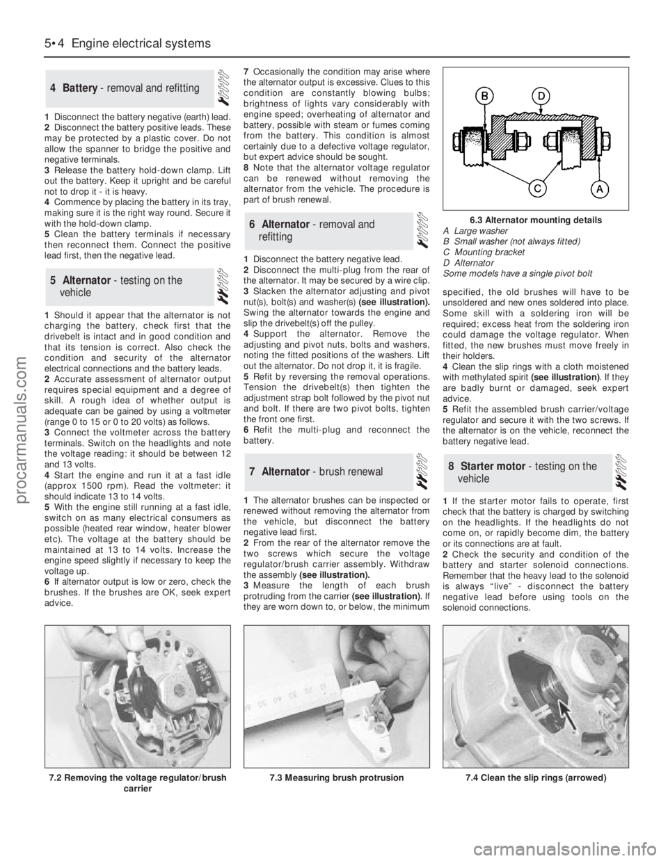
nut(s), bolt(s)and washer(s)(see illustration).
Swing the alternator towards the engine and
slip the drivebelt(s) off the pulley.
4Support the alternator. Remove the
adjusting and pivot nuts, bolts and washers,
noting the fitted positions of the washers. Lift
out the alternator. Do not drop it, it is fragile.
5Refit by reversing the removal operations.
Tension the drivebelt(s) then tighten the
adjustment strap bolt followed by the pivot nut
and bolt. If there are two pivot bolts, tighten
the front one first.
6Refit the multi-plug and reconnect the
battery.
1The alternator brushes can be inspected or
renewed without removing the alternator from
the vehicle, but disconnect the battery
negative lead first.
2From the rear of the alternator remove the
two screws which secure the voltage
regulator/brush carrier assembly. Withdraw
the assembly (see illustration).
3Measure the length of each brush
protruding from the carrier (see illustration). If
they are worn down to, or below, the minimumspecified, the old brushes will have to be
unsoldered and new ones soldered into place.
Some skill with a soldering iron will be
required; excess heat from the soldering iron
could damage the voltage regulator. When
fitted, the new brushes must move freely in
their holders.
4Clean the slip rings with a cloth moistened
with methylated spirit (see illustration). If they
are badly burnt or damaged, seek expert
advice.
5Refit the assembled brush carrier/voltage
regulator and secure it with the two screws. If
the alternator is on the vehicle, reconnect the
battery negative lead.
1If the starter motor fails to operate, first
check that the battery is charged by switching
on the headlights. If the headlights do not
come on, or rapidly become dim, the battery
or its connections are at fault.
2Check the security and condition of the
battery and starter solenoid connections.
Remember that the heavy lead to the solenoid
is always “live” - disconnect the battery
negative lead before using tools on the
solenoid connections.
8Starter motor - testing on the
vehicle7Alternator - brush renewal
6Alternator - removal and
refitting
5Alternator - testing on the
vehicle
4Battery - removal and refitting
5•4Engine electrical systems
7.3 Measuring brush protrusion7.4 Clean the slip rings (arrowed)
6.3 Alternator mounting details
A Large washer
B Small washer (not always fitted)
C Mounting bracket
D Alternator
Some models have a single pivot bolt
7.2 Removing the voltage regulator/brush
carrier
procarmanuals.com
Page 178 of 255
Chapter 13
Body electrical system
Anti-theft alarm system components - removal and refitting . . . . . .36
Auxiliary warning system components - testing, removal and
refitting . . . . . . . . . . . . . . . . . . . . . . . . . . . . . . . . . . . . . . . . . . . . .27
Central locking motor - removal and refitting . . . . . . . . . . . . . . . . . .17
Cigarette lighter - removal and refitting . . . . . . . . . . . . . . . . . . . . . .10
Clock - removal and refitting . . . . . . . . . . . . . . . . . . . . . . . . . . . . . . .9
Electrical fault-finding - general information . . . . . . . . . . . . . . . . . . .2
Exterior lights - bulb renewal . . . . . . . . . . . . . . . . . . . . . . . . . . . . . . .3
Exterior light units - removal and refitting . . . . . . . . . . . . . . . . . . . . .4
Fuel computer components - removal and refitting . . . . . . . . . . . . .26
Fuses, relays and control units - removal and refitting . . . . . . . . . .16
General information . . . . . . . . . . . . . . . . . . . . . . . . . . . . . . . . . . . . . .1
Headlight beam alignment . . . . . . . . . . . . . . . . . . . . . . . . . . . . . . . . .5
Heater blower motor - removal and refitting . . . . . . . . . . . . . . . . . .29
Horn - removal and refitting . . . . . . . . . . . . . . . . . . . . . . . . . . . . . . .11
Horn switch plate, slip rings and brushes - removal and refitting . .12
Ignition/starter switch - removal and refitting . . . . . . . . . . . . . . . . . .14
Instrument cluster - dismantling and reassembly . . . . . . . . . . . . . . .8
Instrument cluster - removal and refitting . . . . . . . . . . . . . . . . . . . . .7
Interior lights - bulb renewal . . . . . . . . . . . . . . . . . . . . . . . . . . . . . . . .6Joystick fader control - removal and refitting . . . . . . . . . . . . . . . . . .33
Loudspeakers (original equipment) - removal and refitting . . . . . . .31
Radio aerial pre-amplifier (original equipment) - removal and
refitting . . . . . . . . . . . . . . . . . . . . . . . . . . . . . . . . . . . . . . . . . . . . .32
Radio or radio/cassette player (original equipment) - removal and
refitting . . . . . . . . . . . . . . . . . . . . . . . . . . . . . . . . . . . . . . . . . . . . .30
Rear entertainment console - removal and refitting . . . . . . . . . . . . .34
Rear headphone relay - removal and refitting . . . . . . . . . . . . . . . . .35
Rear window wiper motor - removal and refitting . . . . . . . . . . . . . .24
Seat adjusting motors - removal and refitting . . . . . . . . . . . . . . . . .19
Seat heating elements - removal and refitting . . . . . . . . . . . . . . . . .13
Sliding roof motor - removal and refitting . . . . . . . . . . . . . . . . . . . .20
Speed control system components - removal and refitting . . . . . . .28
Speedometer sender unit - removal and refitting . . . . . . . . . . . . . . .21
Switches - removal and refitting . . . . . . . . . . . . . . . . . . . . . . . . . . . .15
Window operating motor - removal and refitting . . . . . . . . . . . . . . .18
Windscreen, rear window and headlight washer components -
removal and refitting . . . . . . . . . . . . . . . . . . . . . . . . . . . . . . . . . . .25
Windscreen wiper motor and linkage - removal and refitting . . . . .23
Wiper arms and blades - removal and refitting . . . . . . . . . . . . . . . .22
General
System type . . . . . . . . . . . . . . . . . . . . . . . . . . . . . . . . . . . . . . . . . . . . . . 12 volt, negative earth
Light bulbs (typical)Fitting Wattage
Headlights . . . . . . . . . . . . . . . . . . . . . . . . . . . . . . . . . . . . . . . . . . . . . . . . H4 60/55
Auxiliary driving lights and front foglights . . . . . . . . . . . . . . . . . . . . . . . . H3 55
Side/parking lights . . . . . . . . . . . . . . . . . . . . . . . . . . . . . . . . . . . . . . . . . Glass base 5
Direction indicators, reversing light and rear foglight . . . . . . . . . . . . . . . Bayonet 21
Stop and tail lights . . . . . . . . . . . . . . . . . . . . . . . . . . . . . . . . . . . . . . . . . Bayonet 21/5
Door open/kerb illumination lights, luggage area light . . . . . . . . . . . . . . Bayonet 5
Number plate lights, reading light and footwell lights . . . . . . . . . . . . . . Glass base 5
Engine bay light . . . . . . . . . . . . . . . . . . . . . . . . . . . . . . . . . . . . . . . . . . . Bayonet 10
Interior lights . . . . . . . . . . . . . . . . . . . . . . . . . . . . . . . . . . . . . . . . . . . . . . Festoon 10
Vanity mirror light . . . . . . . . . . . . . . . . . . . . . . . . . . . . . . . . . . . . . . . . . . Festoon 3
Glovebox light . . . . . . . . . . . . . . . . . . . . . . . . . . . . . . . . . . . . . . . . . . . . . Glass base 3
Ashtray light . . . . . . . . . . . . . . . . . . . . . . . . . . . . . . . . . . . . . . . . . . . . . . Glass base 1.2
Instrument illumination, pilot and warning lights . . . . . . . . . . . . . . . . . . Glass base 1.2/2.5
Heater control light . . . . . . . . . . . . . . . . . . . . . . . . . . . . . . . . . . . . . . . . . Glass base 1
Automatic transmission selector light and clock light . . . . . . . . . . . . . . Bayonet 1.4
Fuses and circuit breakers- main fuse box
Fuse No Rating (A) Circuit(s) protected
1 20 . . . . . . . . . . . . . . . . . . . . . . . . . . . . . . . . . . . . . . . . . . . . . . . LH main beam, LH auxiliary driving light
2 20 . . . . . . . . . . . . . . . . . . . . . . . . . . . . . . . . . . . . . . . . . . . . . . . RH main beam, LH auxiliary driving light
3 10 . . . . . . . . . . . . . . . . . . . . . . . . . . . . . . . . . . . . . . . . . . . . . . . LH dipped beam
4 10 . . . . . . . . . . . . . . . . . . . . . . . . . . . . . . . . . . . . . . . . . . . . . . . RH dipped beam
5 10 . . . . . . . . . . . . . . . . . . . . . . . . . . . . . . . . . . . . . . . . . . . . . . . LH side and tail lights
6 10 . . . . . . . . . . . . . . . . . . . . . . . . . . . . . . . . . . . . . . . . . . . . . . . RH side and tail lights
13•1
Easy,suitable for
novice with little
experienceFairly easy,suitable
for beginner with
some experienceFairly difficult,
suitable for competent
DIY mechanicDifficult,suitable for
experienced DIY
mechanicVery difficult,
suitable for expert
DIY or professional
Degrees of difficulty
Specifications Contents
13
procarmanuals.com
Page 181 of 255
the circuit between the relevant connector and
the battery is problem-free.
13Continue to check the remainder of the
circuit in the same fashion.
14When a point is reached at which no
voltage is present, the problem must lie
between that point and the previous test point
with voltage. Most problems can be traced to
a broken, corroded or loose connection.
Finding a short-circuit
15To check for a short-circuit, first disconnect
the load(s) from the circuit (loads are the
components which draw current from a circuit,
such as bulbs, motors, heating elements, etc).
16Remove the relevant fuse from the circuit,
and connect a circuit tester or voltmeter to the
fuse connections.
17Switch on the circuit, bearing in mind that
some circuits are live only when the ignition
switch is moved to a particular position.
18If voltage is present (indicated either by
the tester bulb lighting or a voltmeter reading),
this means that there is a short-circuit.
19If no voltage is present, but the fuse still
blows with the load(s) connected, this
indicates an internal fault in the load(s).
Finding an earth fault
20The battery negative terminal is connected
to “earth” - the metal of the engine/transmission
and the car body - and most systems are wired
so that they only receive a positive feed, the
current returning via the metal of the car body.
This means that the component mounting andthe body form part of that circuit. Loose or
corroded mountings can therefore cause a range
of electrical faults, ranging from total failure of a
circuit, to a puzzling partial fault. In particular,
lights may shine dimly (especially when another
circuit sharing the same earth is in operation),
motors (eg wiper motors or the radiator cooling
fan motor) may run slowly, and the operation of
one circuit may have an apparently-unrelated
effect on another. Note that on many vehicles,
earth straps are used between certain
components, such as the engine/transmission
and the body, usually where there is no metal-to-
metal contact between components, due to
flexible rubber mountings, etc.
21To check whether a component is properly
earthed, disconnect the battery, and connect
one lead of an ohmmeter to a known good
earth point. Connect the other lead to the wire
or earth connection being tested. The
resistance reading should be zero; if not,
check the connection as follows.
22If an earth connection is thought to be
faulty, dismantle the connection, and clean
back to bare metal both the bodyshell and the
wire terminal, or the component’s earth
connection mating surface. Be careful to
remove all traces of dirt and corrosion, then
use a knife to trim away any paint, so that a
clean metal-to-metal joint is made. On
reassembly, tighten the joint fasteners
securely; if a wire terminal is being refitted, use
serrated washers between the terminal and
the bodyshell, to ensure a clean and secure
connection. When the connection is remade,
prevent the onset of corrosion in the future byapplying a coat of petroleum jelly or silicone-
based grease, or by spraying on (at regular
intervals) a proprietary ignition sealer, or a
water-dispersant lubricant.
Headlight
1Open and prop the bonnet. Remove the
cover from the rear of the headlight unit by
twisting it anti-clockwise.
2Disconnect the wiring plug from the
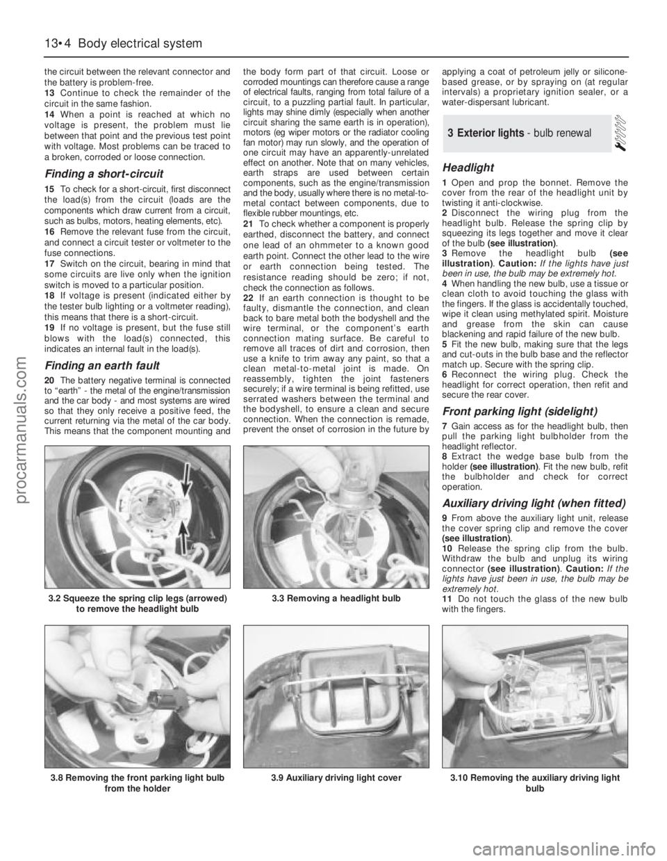
headlight bulb. Release the spring clip by
squeezing its legs together and move it clear
of the bulb (see illustration).
3Remove the headlight bulb (see
illustration). Caution: If the lights have just
been in use, the bulb may be extremely hot.
4When handling the new bulb, use a tissue or
clean cloth to avoid touching the glass with
the fingers. If the glass is accidentally touched,
wipe it clean using methylated spirit. Moisture
and grease from the skin can cause
blackening and rapid failure of the new bulb.
5Fit the new bulb, making sure that the legs
and cut-outs in the bulb base and the reflector
match up. Secure with the spring clip.
6Reconnect the wiring plug. Check the
headlight for correct operation, then refit and
secure the rear cover.
Front parking light (sidelight)
7Gain access as for the headlight bulb, then
pull the parking light bulbholder from the
headlight reflector.
8Extract the wedge base bulb from the
holder (see illustration). Fit the new bulb, refit
the bulbholder and check for correct
operation.
Auxiliary driving light (when fitted)
9From above the auxiliary light unit, release
the cover spring clip and remove the cover
(see illustration).
10Release the spring clip from the bulb.
Withdraw the bulb and unplug its wiring
connector (see illustration). Caution: If the
lights have just been in use, the bulb may be
extremely hot.
11Do not touch the glass of the new bulb
with the fingers.
3Exterior lights - bulb renewal
13•4Body electrical system
3.2 Squeeze the spring clip legs (arrowed)
to remove the headlight bulb3.3 Removing a headlight bulb
3.8 Removing the front parking light bulb
from the holder3.9 Auxiliary driving light cover3.10 Removing the auxiliary driving light
bulb
procarmanuals.com
Page 183 of 255
1For removal and refitting of the front
foglights, front direction indicators, direction
indicator repeaters and the number plate
lights, refer to the previous Section.
Headlight
2Unhook the direction indicator light unit
retaining spring. Withdraw the direction
indicator unit and allow it to hang.
3Pull out the rubber moulding from between
the base of the headlight and the bumper.
(This moulding may in fact be stuck to the
headlight surround.)
4Release the headlight surround retaininglugs, prising them carefully with a screwdriver.
Work from the outside towards the centre of
the vehicle. Remove the surround by pulling it
forwards and then sideways.
5Remove the radiator grille, secured by two
screws.
6Disconnect the headlight wiring connector.
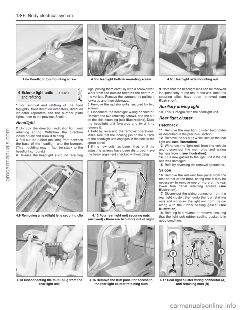
Remove the two retaining screws, and the nut
on the side mounting (see illustrations). Draw
the headlight unit forwards and twist it to
remove it.
7Refit by reversing the removal operations.
Make sure that the locating pin on the outside
of the headlight unit engages in the hole in the
apron panel.
8If the new unit has been fitted, or if the
adjusting screws have been disturbed, have
the beam alignment checked without delay.9Note that the headlight lens can be renewed
independently of the rest of the unit, once the
securing clips have been removed (see
illustration).
Auxiliary driving light
10This is integral with the headlight unit.
Rear light cluster
Hatchback
11Remove the rear light cluster bulbholder
as described in the previous Section.
12Remove the six nuts which secure the rear
light unit (see illustration).
13Withdraw the light unit from the vehicle
and disconnect the multi-plug and wiring
harness from it (see illustration).
14Fit a new gasket to the light unit if the old
one was damaged.
15Refit by reversing the removal operations.
Saloon
16Remove the relevant trim panel from the
rear corner of the boot, noting that it may be
necessary to remove one or more of the rear
lower trim panel retaining screws (see
illustration).
17Disconnect the wiring connector from the
rear light cluster, then undo the four retaining
nuts and withdraw the light unit from the car
along with the rubber sealing gasket (see
illustration).
18Refitting is a reverse of removal ensuring
that the light unit rubber sealing gasket is in
good condition.
4Exterior light units - removal
and refitting
13•6Body electrical system
4.6a Headlight top mounting screw
4.13 Disconnecting the multi-plug from the
rear light unit
4.9 Removing a headlight lens securing clip4.12 Four rear light unit securing nuts
(arrowed) - there are two more out of sight
4.16 Remove the trim panel for access to
the rear light cluster retaining nuts4.17 Rear light cluster wiring connector (A)
and retaining nuts (B)
4.6b Headlight bottom mounting screw4.6c Headlight side mounting nut
procarmanuals.com
Page 184 of 255
Estate
19This procedure is the same as described
above for the Saloon models noting that it is
necessary to remove the luggage
compartment side trim panel to gain access to
the light cluster retaining nuts.
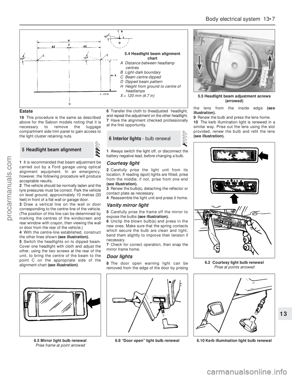
1It is recommended that beam adjustment be
carried out by a Ford garage using optical
alignment equipment. In an emergency,
however, the following procedure will produce
acceptable results.
2The vehicle should be normally laden and the
tyre pressures must be correct. Park the vehicle
on level ground, approximately 10 metres (33
feet) in front of a flat wall or garage door.
3Draw a vertical line on the wall or door
corresponding to the centre-line of the vehicle.
(The position of this line can be determined by
marking the centres of the windscreen and
rear window with crayon, then viewing the wall
or door from the rear of the vehicle.)
4With the centre-line established, construct
the other lines shown (see illustration).
5Switch the headlights on to dipped beam.
Cover one headlight with cloth and adjust the
other, using the two screws at the rear of the
unit, to bring the centre of the beam to the
point C on the appropriate side of the
alignment chart (see illustration).6Transfer the cloth to theadjusted headlight,
and repeat the adjustment on the other headlight.
7Have the alignment checked professionally
at the first opportunity.
1Always switch the light off, or disconnect the
battery negative lead, before changing a bulb.
Courtesy light
2Carefully prise the light unit from its
location. If reading (spot) lights are fitted, prise
from the middle; if not, prise from one end
(seeillustration).
3Renew the bulb(s), detaching the reflector or
contact plate as necessary.
4Reassemble the light unit and press it home.
Vanity mirror light
5Carefully prise the frame off the mirror to
expose the bulbs(see illustration).
6Unclip the blown bulb(s) and press in the
new ones. Make sure that the spring contacts
which secure the bulb are clean and tight;
bend them slightly to improve their tension if
necessary.
7Check for correct operation, then snap the
mirror frame home.
Door lights
8The door open warning light can be
removed from the edge of the door by prisingthe lens from the inside edge (see
illustration).
9Renew the bulb and press the lens home.
10The kerb illumination light is renewed in a
similar way. Prise out the lens using the slot
provided, renew the bulb and refit the lens
(seeillustration).
6Interior lights - bulb renewal
5Headlight beam alignment
Body electrical system 13•7
13
5.5 Headlight beam adjustment screws
(arrowed)
6.2 Courtesy light bulb renewal
Prise at points arrowed
6.8 “Door open” light bulb renewal6.5 Mirror light bulb renewal
Prise frame at point arrowed
5.4 Headlight beam alignment
chart
A Distance between headlamp
centres
B Light-dark boundary
C Beam centre dipped
D Dipped beam pattern
H Height from ground to centre of
headlamps
X = 120 mm (4.7 in)
6.10 Kerb illumination light bulb renewal
procarmanuals.com
Page 254 of 255
Q
Quarter window moulding - 12•10
R
Radiator - 3•3, 12•9
Radio fader light - 13•8
Radio or radio/cassette player - 13•20, 13•21
Rear light cluster - 13•5, 13•6
Recline motor - 13•15
Regulator mechanism - 12•9
Relays - 13•13
Respraying - 12•3
Reversing light switch - 7B•3, 13•12, 13•13
Ride height control - 11•12, 11•13
Road test - 1•16
Rocker shaft - 2C•12
Rotor arm - 5•5
Routine maintenance and servicing- 1•1et
seq
Rust holes or gashes in bodywork - 12•2
S
Safety first! - 0•5
Scalding - 0•5
Scratches in bodywork - 12•2
Screw threads and fastenings - REF•4
Seals and hoses - 1•19
Seat air cushion - 12•17
Seat belts - 0•12, 1•10, 12•17, 12•18
Seats - 0•12, 12•17, 12•18, 13•10, 13•13,
13•15
Selector rod - 7B•4
Servo - 10•12, 10•13, 13•20
Shock absorbers - 0•12, 0•13, 11•12
Short-circuit - 13•4
Side mouldings - 12•10
Sidelight - 13•4
Sliding roof - 12•5, 13•12, 13•16
Spare parts - 0•8
Spark plugs - 1•12, 5•5
Speakers - 13•21, 13•22
Speed control system components - 13•19,
13•20
Speedometer sender unit - 13•16
Spoiler - 12•11
Springs - 0•13, 11•11
Starter inhibitor/reversing light switch -
7B•3, 13•13
Starter motor - 5•4, 5•5
Starter motor noisy or excessively-rough in
engagement - REF•6
Starter motor turns engine slowly - REF•6
Steering and suspension - 0•12, 0•13, 1•15,
1•16, 11•1et seq,REF•10
Steering column- 0•11, 11•5
Steering gear - 11•3
Steering intermediate shaft and flexible
coupling - 11•6Steering play - REF•10
Steering rack bellows - 11•4
Steering stiff - REF•10
Steering wheel - 0•11, 11•4, 11•5
Steering wheel and column -
Stop-light switch - 13•12
Strut - 11•9, 11•10
Stub axle carrier - 11•7
Sump - 2A•9, 2A•16, 2B•15, 2C•9, 2C•19
Switch illumination lights - 13•8
Switches - 13•9, 13•11, 13•12, 13•13,
13•18, 13•19
T
Tailgate - 12•4, 12•7, 13•12, 13•18
Tailgate wash/wipe inoperative, or
unsatisfactory in operation - REF•11
Tailgate window mouldings - 12•10
Tappets - 2C•13
Temperature gauge gives false reading -
REF•11
Temperature gauge sender - 3•7
Thermostat - 3•3
Throttle body - 4•15
Throttle cable - 4•7
Throttle kicker - 4•13
Throttle pedal - 4•6
Throttle position sensor - 4•15
Timing belt - 2A•8, 2A•14, 2A•18
Timing chain - 2B•8, 2B•10, 2C•9, 2C•17
Tools and working facilities- REF•1et seq
Towing - 0•7
Track rod end - 11•6
Transmission fluid brown, or has burned
smell - REF•9
Transmission slips, shifts roughly, is noisy,
or has no drive in forward or reverse
gears - REF•9
Transmission will not downshift (kickdown)
with accelerator pedal fully depressed -
REF•9
Tyre wear - REF•10
Tyres - 0•14, 1•7
U
Ultrasonic sensor - 13•23
Underbody inspection - 1•15
Unleaded fuel - 4•23
V
Vacuum dump valve/switch - 13•19
Vacuum hoses - 2C•7
Vacuum line modification - 7B•4
Vacuum pull-down adjustment - 4•13
Vacuum pump - 13•20
Vacuum servo - 10•12, 10•13, 13•20
Valve block and pump assembly - 10•13
Valve clearances - 1•13, 2A•20, 2C•21Valve grinding - 2A•14
Vane airflow meter(s) - 4•16
Vanity mirror light - 13•7
Vapour separator - 4•7
Vehicle identification - 0•9, 0•12
Vehicle pulls to one side - REF•9, REF•10
Vehicle speed sensor - 5•12
Vibration damper (MT75type gearbox) - 8•4
Viscous-coupled fan - 3•5
W
Wandering or general instability - REF•10
Warning light bulbs - 13•18
Wash/wipe inoperative, or unsatisfactory in
operation - REF•11
Wash/wipe switch - 13•12
Washer fluid - 1•7, 13•19
Washer jets inoperative - REF•11
Washer pump fails to operate - REF•11
Washer pump runs for some time before
fluid is emitted from jets - REF•11
Water pump - 3•5
Water pump/alternator drivebelt - 3•7
Weatherstrip - 12•7
Weber 2V carburettor - 4•9, 4•10
Weber 2V TLD carburettor - 4•11, 4•12,
4•13
Wheel alignment - 11•7
Wheel bearings - 0•13, 11•8, 11•11
Wheel changing - 0•7
Wheel sensors - 10•12
Wheel stud - 11•11
Wheel wobble and vibration - REF•10
Wheels - 0•14, 1•10
Wheels locking under normal braking -
REF•10
Window frame mouldings - 12•10
Window glass - 12•8
Window glass fails to move - REF•11
Window glass slow to move - REF•11
Window glass will only move in one
direction - REF•11
Window operating motor - 13•15
Window operating switch - 13•12
Windscreen - 0•11, 12•9
Windscreen mouldings - 12•10
Windscreen, rear window and headlight
washer components - 13•17
Wiper arms and blades - 13•16
Wiper blades - 1•9
Wiper blades fail to clean the glass
effectively - REF•11
Wiper blades sweep over too large or too
small an area of the glass - REF•11
Wiper motor - 13•17
Wipers fail to operate, or operate very
slowly - REF•11
Wiring diagrams- WD•0 et seq
Working facilities - REF•3
IND•3Index
procarmanuals.com