manual radio set FORD GRANADA 1985 Service Repair Manual
[x] Cancel search | Manufacturer: FORD, Model Year: 1985, Model line: GRANADA, Model: FORD GRANADA 1985Pages: 255, PDF Size: 14.98 MB
Page 178 of 255
Chapter 13
Body electrical system
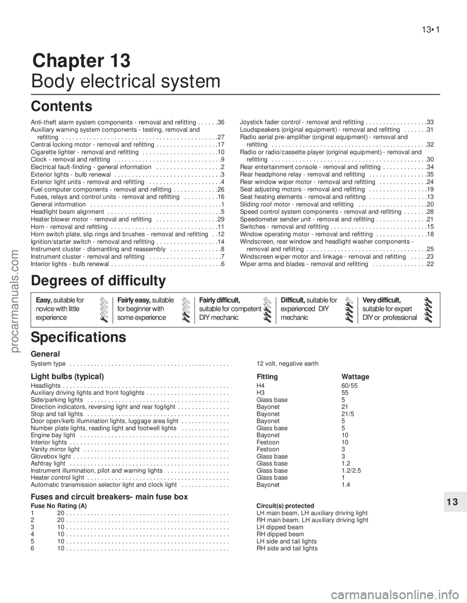
Anti-theft alarm system components - removal and refitting . . . . . .36
Auxiliary warning system components - testing, removal and
refitting . . . . . . . . . . . . . . . . . . . . . . . . . . . . . . . . . . . . . . . . . . . . .27
Central locking motor - removal and refitting . . . . . . . . . . . . . . . . . .17
Cigarette lighter - removal and refitting . . . . . . . . . . . . . . . . . . . . . .10
Clock - removal and refitting . . . . . . . . . . . . . . . . . . . . . . . . . . . . . . .9
Electrical fault-finding - general information . . . . . . . . . . . . . . . . . . .2
Exterior lights - bulb renewal . . . . . . . . . . . . . . . . . . . . . . . . . . . . . . .3
Exterior light units - removal and refitting . . . . . . . . . . . . . . . . . . . . .4
Fuel computer components - removal and refitting . . . . . . . . . . . . .26
Fuses, relays and control units - removal and refitting . . . . . . . . . .16
General information . . . . . . . . . . . . . . . . . . . . . . . . . . . . . . . . . . . . . .1
Headlight beam alignment . . . . . . . . . . . . . . . . . . . . . . . . . . . . . . . . .5
Heater blower motor - removal and refitting . . . . . . . . . . . . . . . . . .29
Horn - removal and refitting . . . . . . . . . . . . . . . . . . . . . . . . . . . . . . .11
Horn switch plate, slip rings and brushes - removal and refitting . .12
Ignition/starter switch - removal and refitting . . . . . . . . . . . . . . . . . .14
Instrument cluster - dismantling and reassembly . . . . . . . . . . . . . . .8
Instrument cluster - removal and refitting . . . . . . . . . . . . . . . . . . . . .7
Interior lights - bulb renewal . . . . . . . . . . . . . . . . . . . . . . . . . . . . . . . .6Joystick fader control - removal and refitting . . . . . . . . . . . . . . . . . .33
Loudspeakers (original equipment) - removal and refitting . . . . . . .31
Radio aerial pre-amplifier (original equipment) - removal and
refitting . . . . . . . . . . . . . . . . . . . . . . . . . . . . . . . . . . . . . . . . . . . . .32
Radio or radio/cassette player (original equipment) - removal and
refitting . . . . . . . . . . . . . . . . . . . . . . . . . . . . . . . . . . . . . . . . . . . . .30
Rear entertainment console - removal and refitting . . . . . . . . . . . . .34
Rear headphone relay - removal and refitting . . . . . . . . . . . . . . . . .35
Rear window wiper motor - removal and refitting . . . . . . . . . . . . . .24
Seat adjusting motors - removal and refitting . . . . . . . . . . . . . . . . .19
Seat heating elements - removal and refitting . . . . . . . . . . . . . . . . .13
Sliding roof motor - removal and refitting . . . . . . . . . . . . . . . . . . . .20
Speed control system components - removal and refitting . . . . . . .28
Speedometer sender unit - removal and refitting . . . . . . . . . . . . . . .21
Switches - removal and refitting . . . . . . . . . . . . . . . . . . . . . . . . . . . .15
Window operating motor - removal and refitting . . . . . . . . . . . . . . .18
Windscreen, rear window and headlight washer components -
removal and refitting . . . . . . . . . . . . . . . . . . . . . . . . . . . . . . . . . . .25
Windscreen wiper motor and linkage - removal and refitting . . . . .23
Wiper arms and blades - removal and refitting . . . . . . . . . . . . . . . .22
General
System type . . . . . . . . . . . . . . . . . . . . . . . . . . . . . . . . . . . . . . . . . . . . . . 12 volt, negative earth
Light bulbs (typical)Fitting Wattage
Headlights . . . . . . . . . . . . . . . . . . . . . . . . . . . . . . . . . . . . . . . . . . . . . . . . H4 60/55
Auxiliary driving lights and front foglights . . . . . . . . . . . . . . . . . . . . . . . . H3 55
Side/parking lights . . . . . . . . . . . . . . . . . . . . . . . . . . . . . . . . . . . . . . . . . Glass base 5
Direction indicators, reversing light and rear foglight . . . . . . . . . . . . . . . Bayonet 21
Stop and tail lights . . . . . . . . . . . . . . . . . . . . . . . . . . . . . . . . . . . . . . . . . Bayonet 21/5
Door open/kerb illumination lights, luggage area light . . . . . . . . . . . . . . Bayonet 5
Number plate lights, reading light and footwell lights . . . . . . . . . . . . . . Glass base 5
Engine bay light . . . . . . . . . . . . . . . . . . . . . . . . . . . . . . . . . . . . . . . . . . . Bayonet 10
Interior lights . . . . . . . . . . . . . . . . . . . . . . . . . . . . . . . . . . . . . . . . . . . . . . Festoon 10
Vanity mirror light . . . . . . . . . . . . . . . . . . . . . . . . . . . . . . . . . . . . . . . . . . Festoon 3
Glovebox light . . . . . . . . . . . . . . . . . . . . . . . . . . . . . . . . . . . . . . . . . . . . . Glass base 3
Ashtray light . . . . . . . . . . . . . . . . . . . . . . . . . . . . . . . . . . . . . . . . . . . . . . Glass base 1.2
Instrument illumination, pilot and warning lights . . . . . . . . . . . . . . . . . . Glass base 1.2/2.5
Heater control light . . . . . . . . . . . . . . . . . . . . . . . . . . . . . . . . . . . . . . . . . Glass base 1
Automatic transmission selector light and clock light . . . . . . . . . . . . . . Bayonet 1.4
Fuses and circuit breakers- main fuse box
Fuse No Rating (A) Circuit(s) protected
1 20 . . . . . . . . . . . . . . . . . . . . . . . . . . . . . . . . . . . . . . . . . . . . . . . LH main beam, LH auxiliary driving light
2 20 . . . . . . . . . . . . . . . . . . . . . . . . . . . . . . . . . . . . . . . . . . . . . . . RH main beam, LH auxiliary driving light
3 10 . . . . . . . . . . . . . . . . . . . . . . . . . . . . . . . . . . . . . . . . . . . . . . . LH dipped beam
4 10 . . . . . . . . . . . . . . . . . . . . . . . . . . . . . . . . . . . . . . . . . . . . . . . RH dipped beam
5 10 . . . . . . . . . . . . . . . . . . . . . . . . . . . . . . . . . . . . . . . . . . . . . . . LH side and tail lights
6 10 . . . . . . . . . . . . . . . . . . . . . . . . . . . . . . . . . . . . . . . . . . . . . . . RH side and tail lights
13•1
Easy,suitable for
novice with little
experienceFairly easy,suitable
for beginner with
some experienceFairly difficult,
suitable for competent
DIY mechanicDifficult,suitable for
experienced DIY
mechanicVery difficult,
suitable for expert
DIY or professional
Degrees of difficulty
Specifications Contents
13
procarmanuals.com
Page 187 of 255
1With the instrument cluster removed, a
particular gauge or other component can be
renewed by following the appropriate parts of
this Section.
2Remove all the light bulbs and holders from
the rear of the panel by twisting them anti-
clockwise.
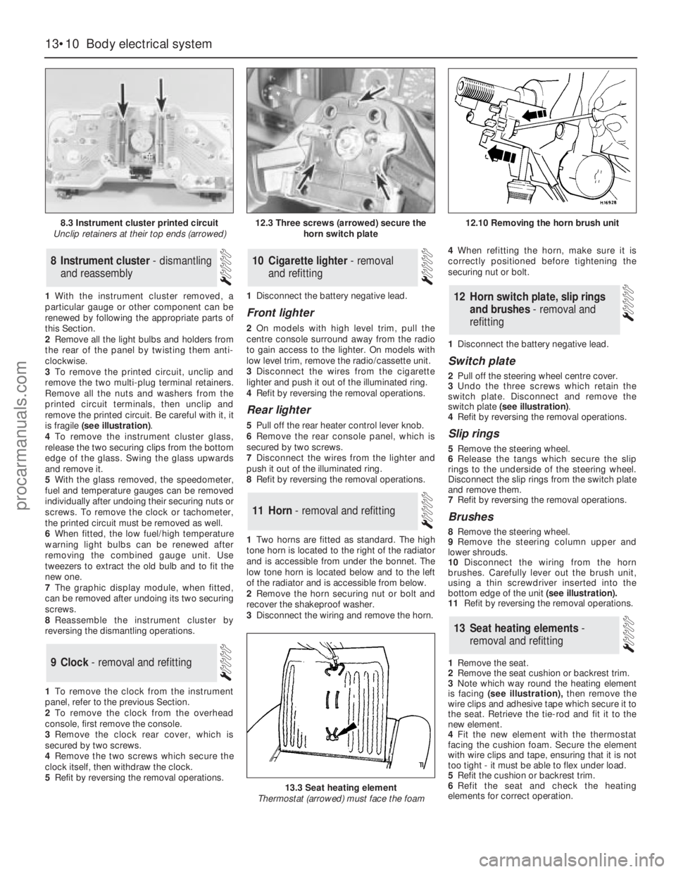
3To remove the printed circuit, unclip and
remove the two multi-plug terminal retainers.
Remove all the nuts and washers from the
printed circuit terminals, then unclip and
remove the printed circuit. Be careful with it, it
is fragile (see illustration).
4To remove the instrument cluster glass,
release the two securing clips from thebottom
edge of the glass. Swing the glass upwards
and remove it.
5With the glass removed, the speedometer,
fuel and temperature gauges can be removed
individually after undoing their securing nuts or
screws. To remove the clock or tachometer,
the printed circuit must be removed as well.
6When fitted, the low fuel/high temperature
warning light bulbs can be renewed after
removing the combined gauge unit. Use
tweezers to extract the old bulb and to fit the
new one.
7The graphic display module, when fitted,
can be removed after undoing its two securing
screws.
8Reassemble the instrument cluster by
reversing the dismantling operations.
1To remove the clock from the instrument
panel, refer to the previous Section.
2To remove the clock from the overhead
console, first remove the console.
3Remove the clock rear cover, which is
secured by two screws.
4Remove the two screws which secure the
clock itself, then withdraw the clock.
5Refit by reversing the removal operations.1Disconnect the battery negative lead.
Front lighter
2On models with high level trim, pull the
centre console surround away from the radio
to gain access to the lighter. On models with
low level trim, remove the radio/cassette unit.
3Disconnect the wires from the cigarette
lighter and push it out of the illuminated ring.
4Refit by reversing the removal operations.
Rear lighter
5Pull off the rear heater control lever knob.
6Remove the rear console panel, which is
secured by two screws.
7Disconnect the wires from the lighter and
push it out of the illuminated ring.
8Refit by reversing the removal operations.
1Two horns are fitted as standard. The high
tone horn is located to the right of the radiator
and is accessible from under the bonnet. The
low tone horn is located below and to the left
of the radiator and is accessible from below.
2Remove the horn securing nut or bolt and
recover the shakeproof washer.
3Disconnect the wiring and remove the horn.4When refitting the horn, make sure it is
correctly positioned before tightening the
securing nut or bolt.
1Disconnect the battery negative lead.
Switch plate
2Pull off the steering wheel centre cover.
3Undo the three screws which retain the
switch plate. Disconnect and remove the
switch plate (see illustration).
4Refit by reversing the removal operations.
Slip rings
5Remove the steering wheel.
6Release the tangs which secure the slip
rings to the underside of the steering wheel.
Disconnect the slip rings from the switch plate
and remove them.
7Refit by reversing the removal operations.
Brushes
8Remove the steering wheel.
9Remove the steering column upper and
lower shrouds.
10Disconnect the wiring from the horn
brushes. Carefully lever out the brush unit,
using a thin screwdriver inserted into the
bottom edge of the unit(see illustration).
11Refit by reversing the removal operations.
1Remove the seat.
2Remove the seat cushion or backrest trim.
3Note which way round the heating element
is facing (see illustration),then remove the
wire clips and adhesive tape which secure it to
the seat. Retrieve the tie-rod and fit it to the
new element.
4Fit the new element with the thermostat
facing the cushion foam. Secure the element
with wire clips and tape, ensuring that it is not
too tight - it must be able to flex under load.
5Refit the cushion or backrest trim.
6Refit the seat and check the heating
elements for correct operation.
13Seat heating elements -
removal and refitting
12Horn switch plate, slip rings
and brushes - removal and
refitting
11Horn - removal and refitting
10Cigarette lighter - removal
and refitting
9Clock - removal and refitting
8Instrument cluster - dismantling
and reassembly
13•10Body electrical system
8.3 Instrument cluster printed circuit
Unclip retainers at their top ends (arrowed)
13.3 Seat heating element
Thermostat (arrowed) must face the foam
12.3 Three screws (arrowed) secure the
horn switch plate12.10 Removing the horn brush unit
procarmanuals.com
Page 190 of 255
Heated rear window switch
Models before April 1992
50Remove the instrument panel surround,
which is secured by four screws.
51Carefully prise the switch from its location,
disconnect the multi-plug and remove it.
Models from April 1992
52Using a small flat-bladed screwdriver,
carefully prise the switch out of the centre
facia vent panel and disconnect the wiring
connector.
53On refitting, reconnect the wiring
connector and push the switch in until it clicks
into position.
Foglight switch(es)
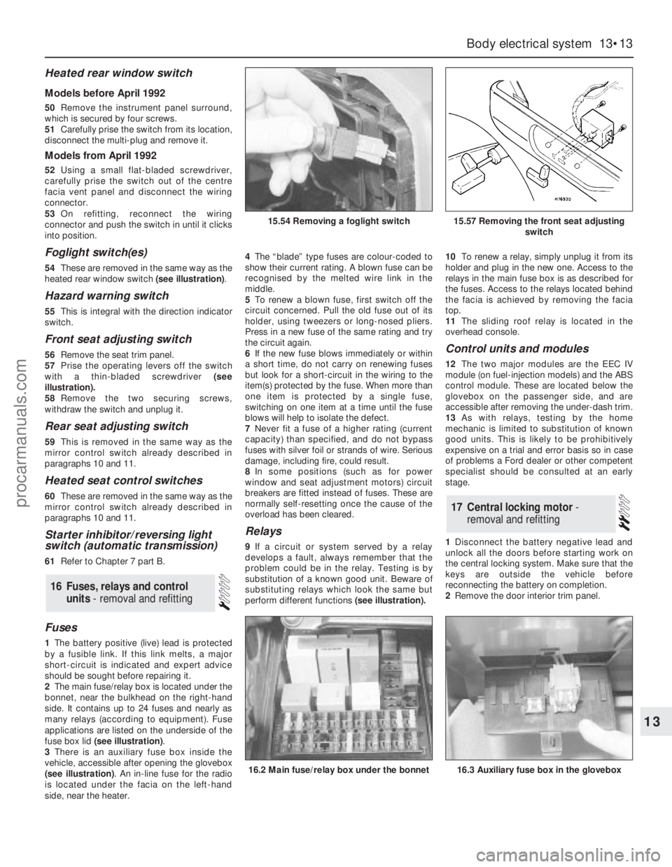
54These are removed in the same way as the
heated rear window switch (see illustration).
Hazard warning switch
55This is integral with the direction indicator
switch.
Front seat adjusting switch
56Remove the seat trim panel.
57Prise the operating levers off the switch
with a thin-bladed screwdriver (see
illustration).
58Remove the two securing screws,
withdraw the switch and unplug it.
Rear seat adjusting switch
59This is removed in the same way as the
mirror control switch already described in
paragraphs 10 and 11.
Heated seat control switches
60These are removed in the same way as the
mirror control switch already described in
paragraphs 10 and 11.
Starter inhibitor/reversing light
switch (automatic transmission)
61Refer to Chapter 7 part B.
Fuses
1The battery positive (live) lead is protected
by a fusible link. If this link melts, a major
short-circuit is indicated and expert advice
should be sought before repairing it.
2The main fuse/relay box is located under the
bonnet, near the bulkhead on the right-hand
side. It contains up to 24 fuses and nearly as
many relays (according to equipment). Fuse
applications are listed on the underside of the
fuse box lid (see illustration).
3There is an auxiliary fuse box inside the
vehicle, accessible after opening the glovebox
(see illustration). An in-line fuse for the radio
is located under the facia on the left-hand
side, near the heater.4The“blade” type fuses are colour-coded to
show their current rating. A blown fuse can be
recognised by the melted wire link in the
middle.
5To renew a blown fuse, first switch off the
circuit concerned. Pull the old fuse out of its
holder, using tweezers or long-nosed pliers.
Press in a new fuse of the same rating and try
the circuit again.
6If the new fuse blows immediately or within
a short time, do not carry on renewing fuses
but look for a short-circuit in the wiring to the
item(s) protected by the fuse. When more than
one item is protected by a single fuse,
switching on one item at a time until the fuse
blows will help to isolate the defect.
7Never fit a fuse of a higher rating (current
capacity) than specified, and do not bypass
fuses with silver foil or strands of wire. Serious
damage, including fire, could result.
8In some positions (such as for power
window and seat adjustment motors) circuit
breakers are fitted instead of fuses. These are
normally self-resetting once the cause of the
overload has been cleared.
Relays
9If a circuit or system served by a relay
develops a fault, always remember that the
problem could be in the relay. Testing is by
substitution of a known good unit. Beware of
substituting relays which look the same but
perform different functions(see illustration).10To renew a relay, simply unplug it from its
holder and plug in the new one. Access to the
relays in the main fuse box is as described for
the fuses. Access to the relays located behind
the facia is achieved by removing the facia
top.
11The sliding roof relay is located in the
overhead console.
Control units and modules
12The two major modules are the EEC IV
module (on fuel-injection models) and the ABS
control module. These are located below the
glovebox on the passenger side, and are
accessible after removing the under-dash trim.
13As with relays, testing by the home
mechanic is limited to substitution of known
good units. This is likely to be prohibitively
expensive on a trial and error basis so in case
of problems a Ford dealer or other competent
specialist should be consulted at an early
stage.
1Disconnect the battery negative lead and
unlock all the doors before starting work on
the central locking system. Make sure that the
keys are outside the vehicle before
reconnecting the battery on completion.
2Remove the door interior trim panel.
17Central locking motor -
removal and refitting
16Fuses, relays and control
units - removal and refitting
Body electrical system 13•13
13
15.54 Removing a foglight switch15.57 Removing the front seat adjusting
switch
16.2 Main fuse/relay box under the bonnet16.3 Auxiliary fuse box in the glovebox
procarmanuals.com
Page 197 of 255
Speed control module
Models before April 1992
9Refer to Section 27. The speed control
module shares the same mountings as the
AWS module; the AWS module is larger.
Models from April 1992
10The speed control module fitted to these
models is situated behind the glovebox on the
left-hand side of the facia. To gain access to
the module remove the left-hand facia
undercover panel. The speed control module
is vertically mounted just to the right of the
engine management module. Push the module
upwards to release the retaining clips then
lower it out from under the facia and
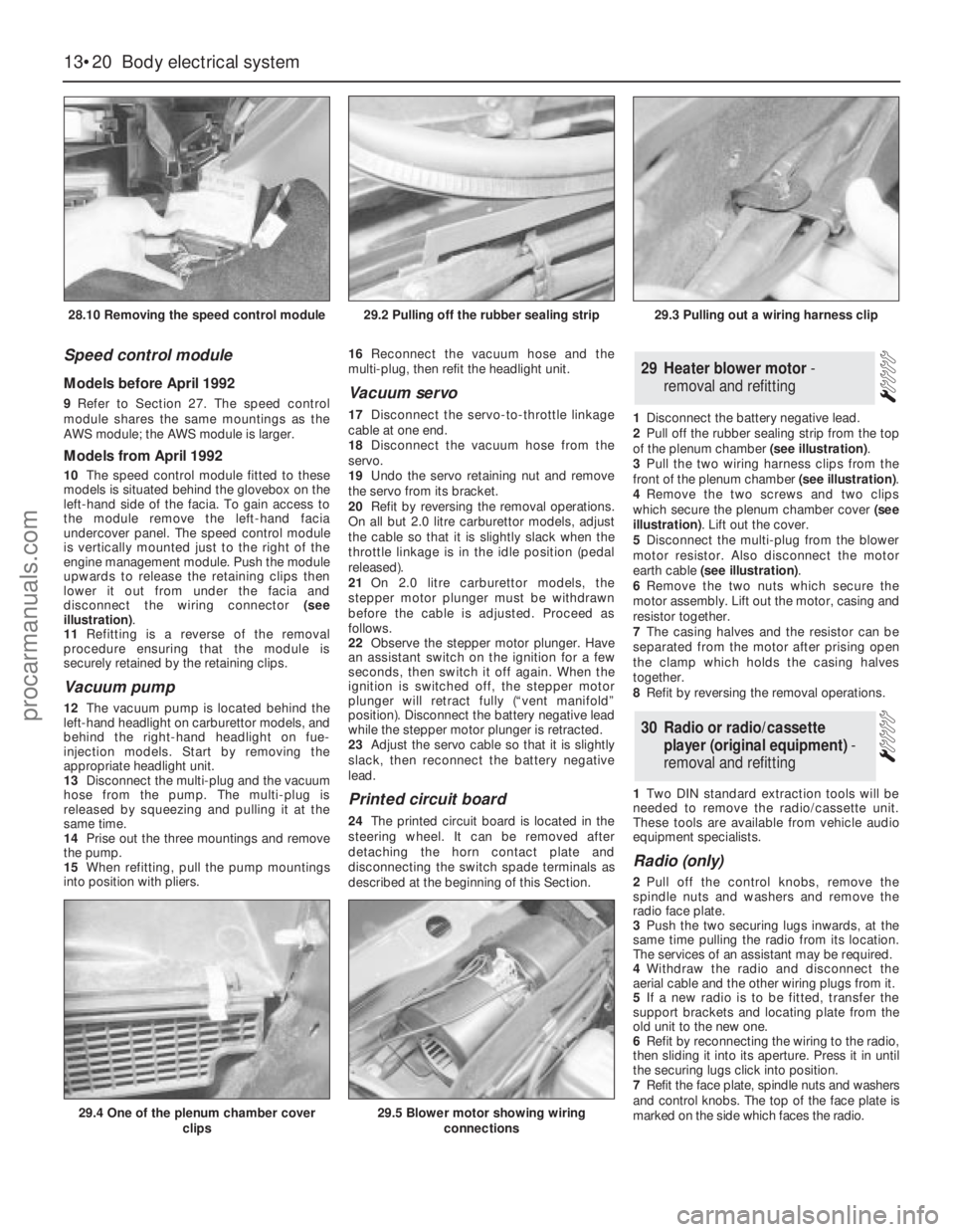
disconnect the wiring connector (see
illustration).
11Refitting is a reverse of the removal
procedure ensuring that the module is
securely retained by the retaining clips.
Vacuum pump
12The vacuum pump is located behind the
left-hand headlight on carburettor models, and
behind the right-hand headlight on fue-
injection models. Start by removing the
appropriate headlight unit.
13Disconnect the multi-plug and the vacuum
hose from the pump. The multi-plug is
released by squeezing and pulling it at the
same time.
14Prise out the three mountings and remove
the pump.
15When refitting, pull the pump mountings
into position with pliers. 16Reconnect the vacuum hose and the
multi-plug, then refit the headlight unit.
Vacuum servo
17Disconnect the servo-to-throttle linkage
cable at one end.
18Disconnect the vacuum hose from the
servo.
19Undo the servo retaining nut and remove
the servo from its bracket.
20Refit by reversing the removal operations.
On all but 2.0 litre carburettor models, adjust
the cable so that it is slightly slack when the
throttle linkage is in the idle position (pedal
released).
21On 2.0 litre carburettor models, the
stepper motor plunger must be withdrawn
before the cable is adjusted. Proceed as
follows.
22Observe the stepper motor plunger. Have
an assistant switch on the ignition for a few
seconds, then switch it off again. When the
ignition is switched off, the stepper motor
plunger will retract fully (“vent manifold”
position). Disconnect the battery negative lead
while the stepper motor plunger is retracted.
23Adjust the servo cable so that it is slightly
slack, then reconnect the battery negative
lead.
Printed circuit board
24The printed circuit board is located in the
steering wheel. It can be removed after
detaching the horn contact plate and
disconnecting the switch spade terminals as
described at the beginning of this Section.1Disconnect the battery negative lead.
2Pull off the rubber sealing strip from the top
of the plenum chamber (see illustration).
3Pull the two wiring harness clips from the
front of the plenum chamber (see illustration).
4Remove the two screws and two clips
which secure the plenum chamber cover (see
illustration). Lift out the cover.
5Disconnect the multi-plug from the blower
motor resistor. Also disconnect the motor
earth cable (see illustration).
6Remove the two nuts which secure the
motor assembly. Lift out the motor, casing and
resistor together.
7The casing halves and the resistor can be
separated from the motor after prising open
the clamp which holds the casing halves
together.
8Refit by reversing the removal operations.
1Two DIN standard extraction tools will be
needed to remove the radio/cassette unit.
These tools are available from vehicle audio
equipment specialists.
Radio (only)
2Pull off the control knobs, remove the
spindle nuts and washers and remove the
radio face plate.
3Push the two securing lugs inwards, at the
same time pulling the radio from its location.
The services of an assistant may be required.
4Withdraw the radio and disconnect the
aerial cable and the other wiring plugs from it.
5If a new radio is to be fitted, transfer the
support brackets and locating plate from the
old unit to the new one.
6Refit by reconnecting the wiring to the radio,
then sliding it into its aperture. Press it in until
the securing lugs click into position.
7Refit the face plate, spindle nuts and washers
and control knobs. The top of the face plate is
marked on the side which faces the radio.
30Radio or radio/cassette
player (original equipment) -
removal and refitting
29Heater blower motor -
removal and refitting
13•20Body electrical system
28.10 Removing the speed control module
29.4 One of the plenum chamber cover
clips29.5 Blower motor showing wiring
connections
29.2 Pulling off the rubber sealing strip29.3 Pulling out a wiring harness clip
procarmanuals.com
Page 198 of 255
8If a new unit has been fitted, trim it by tuning
in a weak medium wave station (around 1500
kHz/200 m) and turning the trimmer screw in
either direction until the best reception is
obtained. On the radio originally fitted, the
trimmer screw is on the front face of the unit;
for other types of radio, consult the
manufacturer’s instructions. Electronic units
are normally self-trimming.
Radio/cassette unit
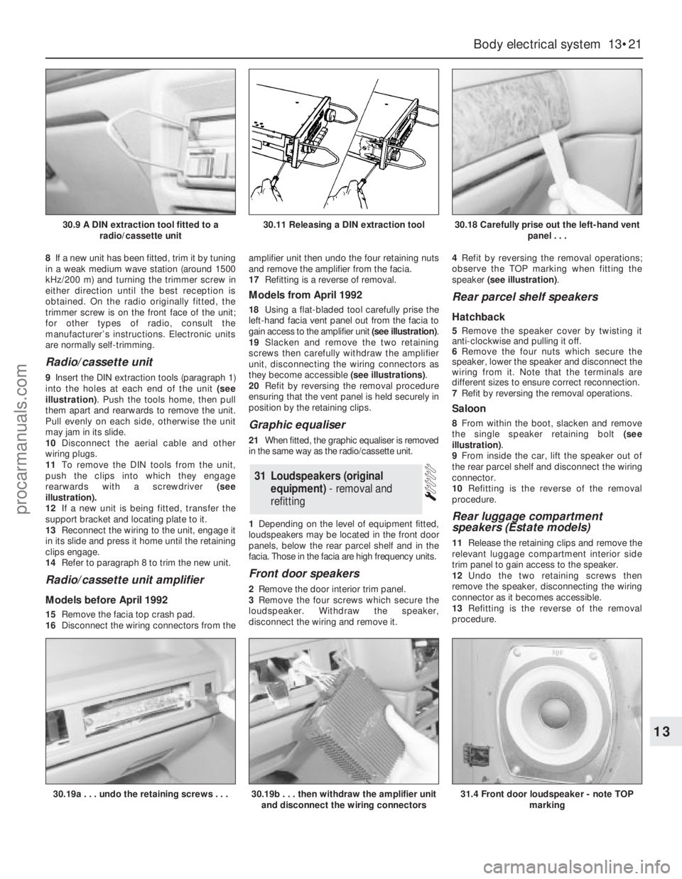
9Insert the DIN extraction tools (paragraph 1)
into the holes at each end of the unit (see
illustration). Push the tools home, then pull
them apart and rearwards to remove the unit.
Pull evenly on each side, otherwise the unit
may jam in its slide.
10Disconnect the aerial cable and other
wiring plugs.
11To remove the DIN tools from the unit,
push the clips into which they engage
rearwards with a screwdriver (see
illustration).
12If a new unit is being fitted, transfer the
support bracket and locating plate to it.
13Reconnect the wiring to the unit, engage it
in its slide and press it home until the retaining
clips engage.
14Refer to paragraph 8 to trim the new unit.
Radio/cassette unit amplifier
Models before April 1992
15Remove the facia top crash pad.
16Disconnect the wiring connectors from theamplifier unit then undo the four retaining nuts
and remove the amplifier from the facia.
17Refitting is a reverse of removal.
Models from April 1992
18Using a flat-bladed tool carefully prise the
left-hand facia vent panel out from the facia to
gain access to the amplifier unit (see illustration).
19Slacken and remove the two retaining
screws then carefully withdraw the amplifier
unit, disconnecting the wiring connectors as
they become accessible (see illustrations).
20Refit by reversing the removal procedure
ensuring that the vent panel is held securely in
position by the retaining clips.
Graphic equaliser
21When fitted, the graphic equaliser is removed
in the same way as the radio/cassette unit.
1Depending on the level of equipment fitted,
loudspeakers may be located in the front door
panels, below the rear parcel shelf and in the
facia. Those in the facia are high frequency units.
Front door speakers
2Remove the door interior trim panel.
3Remove the four screws which secure the
loudspeaker. Withdraw the speaker,
disconnect the wiring and remove it.4Refit by reversing the removal operations;
observe the TOP marking when fitting the
speaker (see illustration).
Rear parcel shelf speakers
Hatchback
5Remove the speaker cover by twisting it
anti-clockwise and pulling it off.
6Remove the four nuts which secure the
speaker, lower the speaker and disconnect the
wiring from it. Note that the terminals are
different sizes to ensure correct reconnection.
7Refit by reversing the removal operations.
Saloon
8From within the boot, slacken and remove
the single speaker retaining bolt (see
illustration).
9From inside the car, lift the speaker out of
the rear parcel shelf and disconnect the wiring
connector.
10Refitting is the reverse of the removal
procedure.
Rear luggage compartment
speakers (Estate models)
11Release the retaining clips and remove the
relevant luggage compartment interior side
trim panel to gain access to the speaker.
12Undo the two retaining screws then
remove the speaker, disconnecting the wiring
connector as it becomes accessible.
13Refitting is the reverse of the removal
procedure.
31Loudspeakers (original
equipment) - removal and
refitting
Body electrical system 13•21
13
30.9 A DIN extraction tool fitted to a
radio/cassette unit30.11 Releasing a DIN extraction tool30.18 Carefully prise out the left-hand vent
panel . . .
30.19a . . . undo the retaining screws . . .30.19b . . . then withdraw the amplifier unit
and disconnect the wiring connectors31.4 Front door loudspeaker - note TOP
marking
procarmanuals.com
Page 199 of 255
High frequency units
14Remove the instrument panel surround
and the facia top.
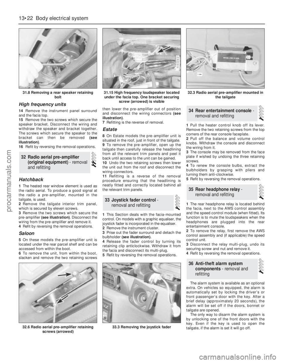
15Remove the two screws which secure the
speaker bracket. Disconnect the wiring and
withdraw the speaker and bracket together.
The screws which secure the speaker to the
bracket can then be removed (see
illustration).
16Refit by reversing the removal operations.
Hatchback
1The heated rear window element is used as
the radio aerial. To produce a good signal at
the radio a pre-amplifier, mounted in the
tailgate, is used.
2Remove the tailgate interior trim panel,
which is secured by eleven screws.
3Remove the two screws which secure the
pre-amplifier (see illustration). Disconnect the
wiring from the pre-amplifier and remove it.
4Refit by reversing the removal operations.
Saloon
5On these models the pre-amplifier unit is
located under the rear parcel shelf and can be
accessed from within the boot.
6To remove the unit, from within the boot,
slacken and remove the two retaining screwsthen lower the pre-amplifier out of position
and disconnect the wiring connectors (see
illustration).
7Refitting is the reverse of removal.
Estate
8On Estate models the pre-amplifier unit is
situated in the roof, just in front of the tailgate.
9To remove the pre-amplifier, open up the
tailgate then carefully release the headlining
from all the relevant trim panels and peel it
back until access to the unit can be gained.
10Undo the two retaining screws then lower
the unit out from the roof and disconnect the
wiring connectors.
11Refitting is a reverse of the removal
procedure ensuring that the headlining is
neatly fitted and correctly located behind all
the relevant trim panels.
1This Section deals with the facia-mounted
control. On models with a graphic equaliser, the
joystick fader is incorporated in the equaliser.
2Remove the instrument cluster.
3Prise out the fader surround and detach the
bulbholder (see illustration).
4Release the fader control by turning its
retaining clip anticlockwise. Withdraw it from
the facia and disconnect its multi-plug.
5Refit by reversing the removal operations.1Pull the heater control knob off its lever.
Remove the two retaining screws from the top
corners of the rear console faceplate.
2Pull off the balance and volume control
knobs. Withdraw the console and disconnect
the wiring from it.
3The console may be removed from the face
plate if wished by undoing the three retaining
screws.
4To renew the console bulbs, extract the
bulbholders by grasping with pliers and
turning them anti-clockwise.
5Refit by reversing the removal operations.
1The rear headphone relay is located behind
the facia, next to the AWS control assembly
and the speed control module (when fitted). Its
function is to mute the loudspeakers when the
headphones are plugged into the rear
entertainment console.
2To remove the relay, first remove the AWS
control assembly and (if applicable) the speed
control unit.
3Disconnect the relay multi-plug, undo its
securing screw and nut and remove it.
4Refit by reversing the removal operations.
The alarm system is available as an optional
extra. On vehicles so equipped, the alarm is
automatically set by locking the driver’s or
front passenger’s door with the key. After a
brief delay (approximately 20 seconds), the
alarm will be set off if the doors, bonnet or
tailgate are opened.
The only way to disarm the alarm system is
by unlocking one of the front doors with the
key. Even if the key is used to open the
tailgate, if the alarm is set it will go off.
36Anti-theft alarm system
components - removal and
refitting
35Rear headphone relay -
removal and refitting
34Rear entertainment console -
removal and refitting
33Joystick fader control -
removal and refitting
32Radio aerial pre-amplifier
(original equipment) - removal
and refitting
13•22Body electrical system
31.8 Removing a rear speaker retaining
bolt
32.6 Radio aerial pre-amplifier retaining
screws (arrowed)33.3 Removing the joystick fader
31.15 High frequency loudspeaker located
under the facia top. One bracket securing
screw (arrowed) is visible32.3 Radio aerial pre-amplifier mounted in
the tailgate
procarmanuals.com
Page 201 of 255
WD•0
Explanatory notes for wiring diagrams
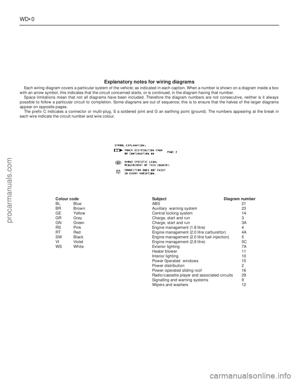
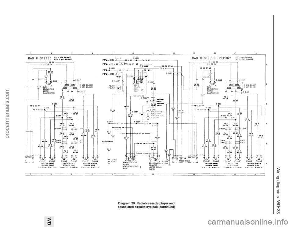
Each wiring diagram covers a particular system of the vehicle; as indicated in each caption. When a number is shown on a diagram inside a box
with an arrow symbol, this indicates that the circuit concerned starts, or is continued, in the diagram having that number.
Space limitations mean that not all diagrams have been included. Therefore the diagram numbers are not consecutive, neither is it always
possible to follow a particular circuit to completion. Some diagrams are out of sequence; this is to ensure that the halves of the larger diagrams
appear on opposite pages.
The prefix C indicates a connector or multi-plug, S a soldered joint and G an earthing point (ground). The numbers appearing at the break in
each wire indicate the circuit number and wire colour.
Colour code
BLBlue
BRBrown
GEYellow
GRGrey
GNGreen
RSPink
RT Red
SWBlack
VIViolet
WSWhiteSubjectDiagram number
ABS21
Auxiliary warning system23
Central locking system14
Charge, start and run3
Charge, start and run3A
Engine management (1.8 litre)4
Engine management (2.0 litre carburettor)4A
Engine management (2.0 litre fuel-injection)5
Engine management (2.8 litre)5C
Exterior lighting7A
Heater blower11
Interior lighting10
Power 0perated windows15
Power distribution2
Power-operated sliding roof16
Radio/cassette player and associated circuits29
Signalling and warning systems9
Wipers and washers12
procarmanuals.com
Page 233 of 255
WD•32Wiring diagrams
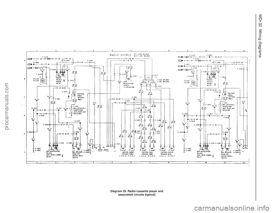
Diagram 29. Radio/cassette player and
associated circuits (typical)
procarmanuals.com
Page 234 of 255
Wiring diagrams WD•33
WD
Diagram 29. Radio/cassette player and
associated circuits (typical) (continued)
procarmanuals.com
Page 254 of 255
Q
Quarter window moulding - 12•10
R
Radiator - 3•3, 12•9
Radio fader light - 13•8
Radio or radio/cassette player - 13•20, 13•21
Rear light cluster - 13•5, 13•6
Recline motor - 13•15
Regulator mechanism - 12•9
Relays - 13•13
Respraying - 12•3
Reversing light switch - 7B•3, 13•12, 13•13
Ride height control - 11•12, 11•13
Road test - 1•16
Rocker shaft - 2C•12
Rotor arm - 5•5
Routine maintenance and servicing- 1•1et
seq
Rust holes or gashes in bodywork - 12•2
S
Safety first! - 0•5
Scalding - 0•5
Scratches in bodywork - 12•2
Screw threads and fastenings - REF•4
Seals and hoses - 1•19
Seat air cushion - 12•17
Seat belts - 0•12, 1•10, 12•17, 12•18
Seats - 0•12, 12•17, 12•18, 13•10, 13•13,
13•15
Selector rod - 7B•4
Servo - 10•12, 10•13, 13•20
Shock absorbers - 0•12, 0•13, 11•12
Short-circuit - 13•4
Side mouldings - 12•10
Sidelight - 13•4
Sliding roof - 12•5, 13•12, 13•16
Spare parts - 0•8
Spark plugs - 1•12, 5•5
Speakers - 13•21, 13•22
Speed control system components - 13•19,
13•20
Speedometer sender unit - 13•16
Spoiler - 12•11
Springs - 0•13, 11•11
Starter inhibitor/reversing light switch -
7B•3, 13•13
Starter motor - 5•4, 5•5
Starter motor noisy or excessively-rough in
engagement - REF•6
Starter motor turns engine slowly - REF•6
Steering and suspension - 0•12, 0•13, 1•15,
1•16, 11•1et seq,REF•10
Steering column- 0•11, 11•5
Steering gear - 11•3
Steering intermediate shaft and flexible
coupling - 11•6Steering play - REF•10
Steering rack bellows - 11•4
Steering stiff - REF•10
Steering wheel - 0•11, 11•4, 11•5
Steering wheel and column -
Stop-light switch - 13•12
Strut - 11•9, 11•10
Stub axle carrier - 11•7
Sump - 2A•9, 2A•16, 2B•15, 2C•9, 2C•19
Switch illumination lights - 13•8
Switches - 13•9, 13•11, 13•12, 13•13,
13•18, 13•19
T
Tailgate - 12•4, 12•7, 13•12, 13•18
Tailgate wash/wipe inoperative, or
unsatisfactory in operation - REF•11
Tailgate window mouldings - 12•10
Tappets - 2C•13
Temperature gauge gives false reading -
REF•11
Temperature gauge sender - 3•7
Thermostat - 3•3
Throttle body - 4•15
Throttle cable - 4•7
Throttle kicker - 4•13
Throttle pedal - 4•6
Throttle position sensor - 4•15
Timing belt - 2A•8, 2A•14, 2A•18
Timing chain - 2B•8, 2B•10, 2C•9, 2C•17
Tools and working facilities- REF•1et seq
Towing - 0•7
Track rod end - 11•6
Transmission fluid brown, or has burned
smell - REF•9
Transmission slips, shifts roughly, is noisy,
or has no drive in forward or reverse
gears - REF•9
Transmission will not downshift (kickdown)
with accelerator pedal fully depressed -
REF•9
Tyre wear - REF•10
Tyres - 0•14, 1•7
U
Ultrasonic sensor - 13•23
Underbody inspection - 1•15
Unleaded fuel - 4•23
V
Vacuum dump valve/switch - 13•19
Vacuum hoses - 2C•7
Vacuum line modification - 7B•4
Vacuum pull-down adjustment - 4•13
Vacuum pump - 13•20
Vacuum servo - 10•12, 10•13, 13•20
Valve block and pump assembly - 10•13
Valve clearances - 1•13, 2A•20, 2C•21Valve grinding - 2A•14
Vane airflow meter(s) - 4•16
Vanity mirror light - 13•7
Vapour separator - 4•7
Vehicle identification - 0•9, 0•12
Vehicle pulls to one side - REF•9, REF•10
Vehicle speed sensor - 5•12
Vibration damper (MT75type gearbox) - 8•4
Viscous-coupled fan - 3•5
W
Wandering or general instability - REF•10
Warning light bulbs - 13•18
Wash/wipe inoperative, or unsatisfactory in
operation - REF•11
Wash/wipe switch - 13•12
Washer fluid - 1•7, 13•19
Washer jets inoperative - REF•11
Washer pump fails to operate - REF•11
Washer pump runs for some time before
fluid is emitted from jets - REF•11
Water pump - 3•5
Water pump/alternator drivebelt - 3•7
Weatherstrip - 12•7
Weber 2V carburettor - 4•9, 4•10
Weber 2V TLD carburettor - 4•11, 4•12,
4•13
Wheel alignment - 11•7
Wheel bearings - 0•13, 11•8, 11•11
Wheel changing - 0•7
Wheel sensors - 10•12
Wheel stud - 11•11
Wheel wobble and vibration - REF•10
Wheels - 0•14, 1•10
Wheels locking under normal braking -
REF•10
Window frame mouldings - 12•10
Window glass - 12•8
Window glass fails to move - REF•11
Window glass slow to move - REF•11
Window glass will only move in one
direction - REF•11
Window operating motor - 13•15
Window operating switch - 13•12
Windscreen - 0•11, 12•9
Windscreen mouldings - 12•10
Windscreen, rear window and headlight
washer components - 13•17
Wiper arms and blades - 13•16
Wiper blades - 1•9
Wiper blades fail to clean the glass
effectively - REF•11
Wiper blades sweep over too large or too
small an area of the glass - REF•11
Wiper motor - 13•17
Wipers fail to operate, or operate very
slowly - REF•11
Wiring diagrams- WD•0 et seq
Working facilities - REF•3
IND•3Index
procarmanuals.com