steering wheel adjustment FORD GRANADA 1985 Service Repair Manual
[x] Cancel search | Manufacturer: FORD, Model Year: 1985, Model line: GRANADA, Model: FORD GRANADA 1985Pages: 255, PDF Size: 14.98 MB
Page 2 of 255
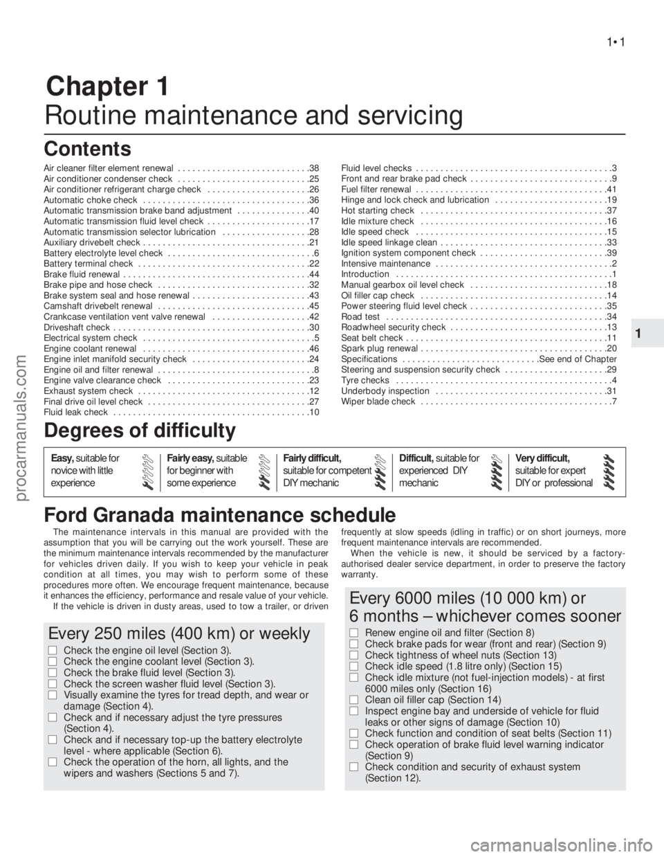
Chapter 1
Routine maintenance and servicing
Air cleaner filter element renewal . . . . . . . . . . . . . . . . . . . . . . . . . . .38
Air conditioner condenser check . . . . . . . . . . . . . . . . . . . . . . . . . . .25
Air conditioner refrigerant charge check . . . . . . . . . . . . . . . . . . . . .26
Automatic choke check . . . . . . . . . . . . . . . . . . . . . . . . . . . . . . . . . .36
Automatic transmission brake band adjustment . . . . . . . . . . . . . . .40
Automatic transmission fluid level check . . . . . . . . . . . . . . . . . . . . .17
Automatic transmission selector lubrication . . . . . . . . . . . . . . . . . .28
Auxiliary drivebelt check . . . . . . . . . . . . . . . . . . . . . . . . . . . . . . . . . .21
Battery electrolyte level check . . . . . . . . . . . . . . . . . . . . . . . . . . . . . .6
Battery terminal check . . . . . . . . . . . . . . . . . . . . . . . . . . . . . . . . . . .22
Brake fluid renewal . . . . . . . . . . . . . . . . . . . . . . . . . . . . . . . . . . . . . .44
Brake pipe and hose check . . . . . . . . . . . . . . . . . . . . . . . . . . . . . . .32
Brake system seal and hose renewal . . . . . . . . . . . . . . . . . . . . . . . .43
Camshaft drivebelt renewal . . . . . . . . . . . . . . . . . . . . . . . . . . . . . . .45
Crankcase ventilation vent valve renewal . . . . . . . . . . . . . . . . . . . .42
Driveshaft check . . . . . . . . . . . . . . . . . . . . . . . . . . . . . . . . . . . . . . . .30
Electrical system check . . . . . . . . . . . . . . . . . . . . . . . . . . . . . . . . . . .5
Engine coolant renewal . . . . . . . . . . . . . . . . . . . . . . . . . . . . . . . . . .46
Engine inlet manifold security check . . . . . . . . . . . . . . . . . . . . . . . .24
Engine oil and filter renewal . . . . . . . . . . . . . . . . . . . . . . . . . . . . . . . .8
Engine valve clearance check . . . . . . . . . . . . . . . . . . . . . . . . . . . . .23
Exhaust system check . . . . . . . . . . . . . . . . . . . . . . . . . . . . . . . . . . .12
Final drive oil level check . . . . . . . . . . . . . . . . . . . . . . . . . . . . . . . . .27
Fluid leak check . . . . . . . . . . . . . . . . . . . . . . . . . . . . . . . . . . . . . . . .10Fluid level checks . . . . . . . . . . . . . . . . . . . . . . . . . . . . . . . . . . . . . . . .3
Front and rear brake pad check . . . . . . . . . . . . . . . . . . . . . . . . . . . . .9
Fuel filter renewal . . . . . . . . . . . . . . . . . . . . . . . . . . . . . . . . . . . . . . .41
Hinge and lock check and lubrication . . . . . . . . . . . . . . . . . . . . . . .19
Hot starting check . . . . . . . . . . . . . . . . . . . . . . . . . . . . . . . . . . . . . .37
Idle mixture check . . . . . . . . . . . . . . . . . . . . . . . . . . . . . . . . . . . . . .16
Idle speed check . . . . . . . . . . . . . . . . . . . . . . . . . . . . . . . . . . . . . . .15
Idle speed linkage clean . . . . . . . . . . . . . . . . . . . . . . . . . . . . . . . . . .33
Ignition system component check . . . . . . . . . . . . . . . . . . . . . . . . . .39
Intensive maintenance . . . . . . . . . . . . . . . . . . . . . . . . . . . . . . . . . . . .2
Introduction . . . . . . . . . . . . . . . . . . . . . . . . . . . . . . . . . . . . . . . . . . . .1
Manual gearbox oil level check . . . . . . . . . . . . . . . . . . . . . . . . . . . .18
Oil filler cap check . . . . . . . . . . . . . . . . . . . . . . . . . . . . . . . . . . . . . .14
Power steering fluid level check . . . . . . . . . . . . . . . . . . . . . . . . . . . .35
Road test . . . . . . . . . . . . . . . . . . . . . . . . . . . . . . . . . . . . . . . . . . . . .34
Roadwheel security check . . . . . . . . . . . . . . . . . . . . . . . . . . . . . . . .13
Seat belt check . . . . . . . . . . . . . . . . . . . . . . . . . . . . . . . . . . . . . . . . .11
Spark plug renewal . . . . . . . . . . . . . . . . . . . . . . . . . . . . . . . . . . . . . .20
Specifications . . . . . . . . . . . . . . . . . . . . . . . . . . . .See end of Chapter
Steering and suspension security check . . . . . . . . . . . . . . . . . . . . .29
Tyre checks . . . . . . . . . . . . . . . . . . . . . . . . . . . . . . . . . . . . . . . . . . . .4
Underbody inspection . . . . . . . . . . . . . . . . . . . . . . . . . . . . . . . . . . .31
Wiper blade check . . . . . . . . . . . . . . . . . . . . . . . . . . . . . . . . . . . . . . .7
The maintenance intervals in this manual are provided with the
assumption that you will be carrying out the work yourself. These are
the minimum maintenance intervals recommended by the manufacturer
for vehicles driven daily. If you wish to keep your vehicle in peak
condition at all times, you may wish to perform some of these
procedures more often. We encourage frequent maintenance, because
it enhances the efficiency, performance and resale value of your vehicle.
If the vehicle is driven in dusty areas, used to tow a trailer, or drivenfrequently at slow speeds (idling in traffic) or on short journeys, more
frequent maintenance intervals are recommended.
When the vehicle is new, it should be serviced by a factory-
authorised dealer service department, in order to preserve the factory
warranty.
1•1
Easy,suitable for
novice with little
experienceFairly easy,suitable
for beginner with
some experienceFairly difficult,
suitable for competent
DIY mechanicDifficult,suitable for
experienced DIY
mechanicVery difficult,
suitable for expert
DIY or professional
Degrees of difficulty Contents
1
Every 250 miles (400 km) or weekly
m mCheck the engine oil level (Section 3).
m mCheck the engine coolant level (Section 3).
m mCheck the brake fluid level (Section 3).
m mCheck the screen washer fluid level (Section 3).
m mVisually examine the tyres for tread depth, and wear or
damage (Section 4).
m mCheck and if necessary adjust the tyre pressures
(Section 4).
m mCheck and if necessary top-up the battery electrolyte
level - where applicable (Section 6).
m mCheck the operation of the horn, all lights, and the
wipers and washers (Sections 5 and 7).
Every 6000 miles (10 000 km) or
6 months – whichever comes sooner
m mRenew engine oil and filter (Section 8)
m mCheck brake pads for wear (front and rear) (Section 9)
m mCheck tightness of wheel nuts (Section 13)
m mCheck idle speed (1.8 litre only) (Section 15)
m mCheck idle mixture (not fuel-injection models) - at first
6000 miles only (Section 16)
m mClean oil filler cap (Section 14)
m mInspect engine bay and underside of vehicle for fluid
leaks or other signs of damage (Section 10)
m mCheck function and condition of seat belts (Section 11)
m mCheck operation of brake fluid level warning indicator
(Section 9)
m mCheck condition and security of exhaust system
(Section 12).
Ford Granada maintenance schedule
procarmanuals.com
Page 17 of 255
Instruments and electrical
equipment
1Check the operation of all instruments and
electrical equipment.
2Make sure that all instruments read
correctly, and switch on all electrical
equipment in turn to check that it functions
properly.
Steering and suspension
3Check for any abnormalities in the steering,
suspension, handling or road “feel”.
4Drive the vehicle, and check that there are
no unusual vibrations or noises.
5Check that the steering feels positive, with
no excessive “sloppiness”, or roughness, and
check for any suspension noises when
cornering, or when driving over bumps.
Drivetrain
6Check the performance of the engine,
clutch, transmission and driveshafts.
7Listen for any unusual noises from the
engine, clutch and transmission.
8Make sure that the engine runs smoothly
when idling, and that there is no hesitation
when accelerating.
9Where applicable, check that the clutch
action is smooth and progressive, that the
drive is taken up smoothly, and that the pedal
travel is not excessive. Also listen for any
noises when the clutch pedal is depressed.
10Check that all gears can be engaged
smoothly, without noise, and that the gear
lever action is not abnormally vague or
“notchy”.
Check the operation and
performance of the braking system
11Make sure that the vehicle does not pull to
one side when braking, and that the wheels do
not lock prematurely when braking hard.
12Check that there is no vibration through
the steering when braking.
13Check that the handbrake operates
correctly, without excessive movement of the
lever, and that it holds the vehicle stationary
on a slope.
14Test the operation of the brake servo unit
as follows. With the engine off, depress the
footbrake four or five times to exhaust the
vacuum. Start the engine, holding the brake
pedal depressed. As the engine starts, there
should be a noticeable “give” in the brake
pedal as vacuum builds up. Allow the engine
to run for at least two minutes, and then
switch it off. If the brake pedal is depressed
now, it should be possible to detect a hiss
from the servo as the pedal is depressed. After
about four or five applications, no further
hissing should be heard, and the pedal should
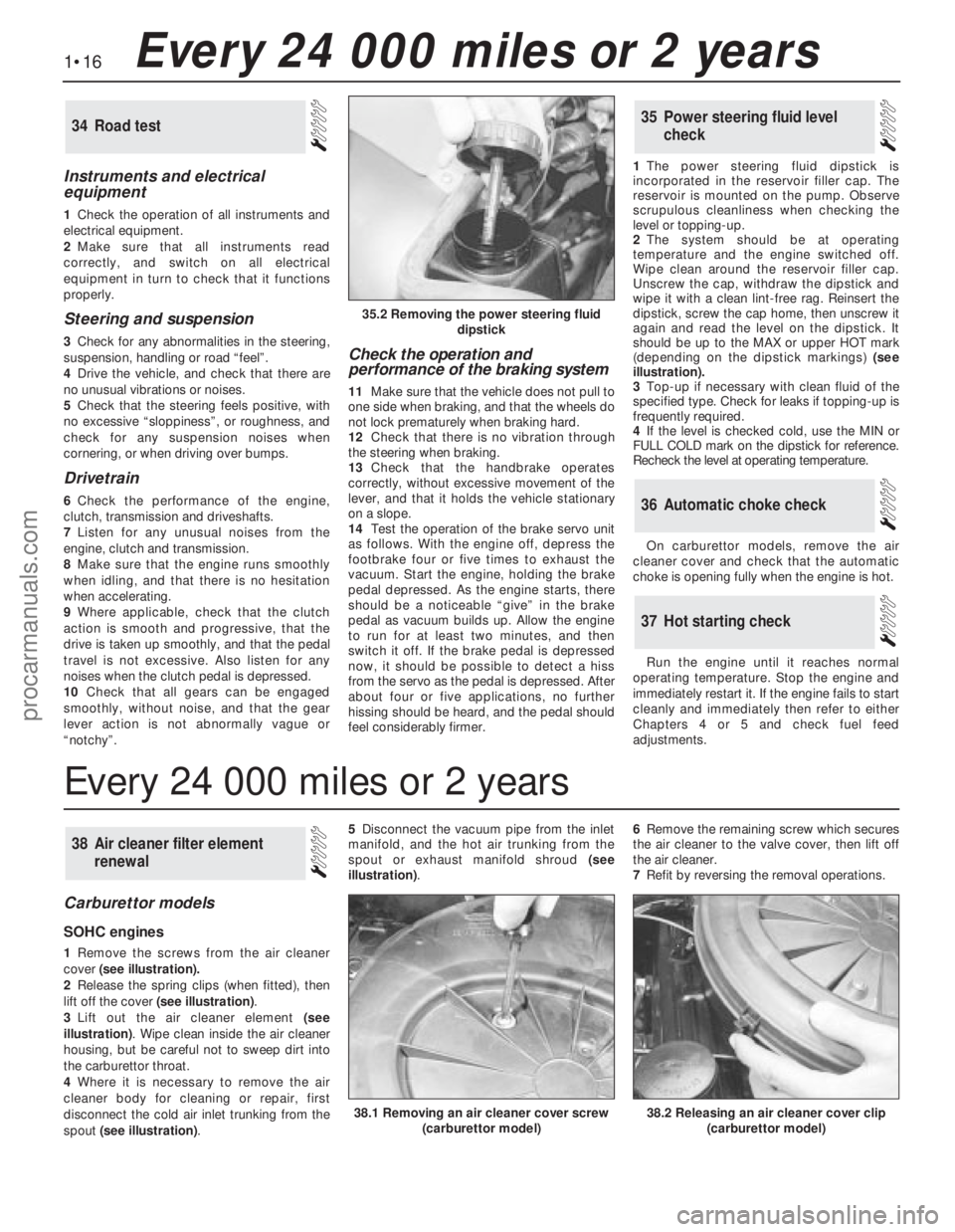
feel considerably firmer.1The power steering fluid dipstick is
incorporated in the reservoir filler cap. The
reservoir is mounted on the pump. Observe
scrupulous cleanliness when checking the
level or topping-up.
2The system should be at operating
temperature and the engine switched off.
Wipe clean around the reservoir filler cap.
Unscrew the cap, withdraw the dipstick and
wipe it with a clean lint-free rag. Reinsert the
dipstick, screw the cap home, then unscrew it
again and read the level on the dipstick. It
should be up to the MAX or upper HOT mark
(depending on the dipstick markings) (see
illustration).
3Top-up if necessary with clean fluid of the
specified type. Check for leaks if topping-up is
frequently required.
4If the level is checked cold, use the MIN or
FULL COLD mark on the dipstick for reference.
Recheck the level at operating temperature.
On carburettor models, remove the air
cleaner cover and check that the automatic
choke is opening fully when the engine is hot.
Run the engine until it reaches normal
operating temperature. Stop the engine and
immediately restart it. If the engine fails to start
cleanly and immediately then refer to either
Chapters 4 or 5 and check fuel feed
adjustments.
37Hot starting check
36Automatic choke check
35Power steering fluid level
check34Road test
Carburettor models
SOHC engines
1Remove the screws from the air cleaner
cover(see illustration).
2Release the spring clips (when fitted), then
lift off the cover (see illustration).
3Lift out the air cleaner element(see
illustration). Wipe clean inside the air cleaner
housing, but be careful not to sweep dirt into
the carburettor throat.
4Where it is necessary to remove the air
cleaner body for cleaning or repair, first
disconnect the cold air inlet trunking from the
spout (see illustration). 5Disconnect the vacuum pipe from the inlet
manifold, and the hot air trunking from the
spout or exhaust manifold shroud(see
illustration). 6Remove the remaining screw which secures
the air cleaner to the valve cover, then lift off
the air cleaner.
7Refit by reversing the removal operations.
38Air cleaner filter element
renewal
1•16Every 24 000 miles or 2 years
35.2 Removing the power steering fluid
dipstick
38.2 Releasing an air cleaner cover clip
(carburettor model)38.1 Removing an air cleaner cover screw
(carburettor model)
Every 24 000 miles or 2 years
procarmanuals.com
Page 50 of 255
21Working through the starter motor
aperture, unscrew the four torque converter-
to-driveplate nuts. It will be necessary to turn
the crankshaft using a spanner on the
crankshaft pulley bolt in order to gain access
to each nut in turn through the aperture.
22Where applicable, remove the bolt
securing the transmission fluid dipstick tube to
the left-hand side of the cylinder block.
23Unscrew the engine-to-transmission bolts,
noting the locations of the bolts, and the
positions of the earth strap and any wiring
clips attached to the bolts. Recover any shims
fitted between the sump and the transmission
when removing the lower engine-to-
transmission bolts.
24Unscrew the bolt from the engine adapter
plate and, where applicable, pull the blanking
plug from the adapter plate.
25Pull the engine and the transmission apart,
ensuring that the torque converter is held firmly
in place in the transmission housing, otherwise
it could fall out resulting in fluid spillage and
possible damage. It may be necessary to rock
the units slightly to separate them.
1Reverse the procedure described in
paragraphs 1 to 40 ofSection 5, noting the
following points.
2Before attempting to refit the engine, check
that the clutch friction disc is centralised.
3Check that the clutch release arm and
bearing are correctly fitted, and lightly grease
the input shaft splines.
4Check that the engine adapter plate is
correctly positioned on the locating dowels. If
necessary, a cable-tie can be used to
temporarily secure the adapter plate in
position on the cylinder block using one of the
engine-to-gearbox bolt holes.
5If shims were fitted between the sump and
the gearbox, refit them in their original
locations when mating the engine to the
gearbox. If the engine has been overhauled,
where applicable fit the relevant shims as
calculated during engine reassembly .
6Reconnect the clutch cable to the release arm,
ensuring that it is routed as noted during removal.
7Ensure that the roadwheels and the steering
wheel are in the straight-ahead position then
align the marks made on removal and reconnect
the intermediate shaft to the steering gearing.
Tighten the clamp bolt to the specified torque.
8Refit the exhaust downpipe.
9Fill the engine with the correct grade and
quantity of oil.
10Check the throttle cable adjustment. Where
necessary, also adjust the speed control cable
in the same way so that there is only a small
amount of slack present in the cable.
11Reconnect the coolant hoses to the water
pump housing.
12Fill the cooling system .
13Tighten all fixings to the specified torque,
where applicable.1Reverse the procedure described in Section 6,
noting the following points.
2Check that the engine adapter plate is
correctly positioned on the locating dowels. If
necessary, a cable-tie can be used to
temporarily secure the adapter plate in
position on the cylinder block using one of the
engine-to-transmission bolt holes.
3As the torque converter is only loosely
engaged in the transmission, care must be taken
to prevent the torque converter from falling out
forwards. When the torque converter hub is fully
engaged with the fluid pump drivegear in the
transmission, distance A (see illustration 2.20 in
Chapter 7B)must be as specified. Incorrect
installation of the torque converter will result in
damageto the transmission.
4If shims were fitted between the sump and
the transmission, refit them in their original
locations when mating the engine to the
transmission. If the engine has been
overhauled, where applicable fit the relevant
shims as calculated during engine reassembly.
5As the engine is installed, guide the torque
converter studs through the holes in the
driveplate. When the engine is positioned flush
with the engine adapter plate and the
transmission housing, check that the torque
converter is free to move axially a small
amount before refitting and tightening the
engine-to-transmission bolts.
6Do not tighten the torque converter-to-
driveplate nuts until the lower engine-to-
transmission bolts have been fitted and
tightened.
7Ensure that the roadwheels and the steering
wheel are in the straight-ahead position then
align the marks made on removal and
reconnect the intermediate shaft to the
steering gearing. Tighten the clamp bolt to the
specified torque.
8Refit the exhaust downpipe.
9Fill the engine with the correct grade and
quantity of oil.
10Check the throttle cable adjustment. Where
necessary, also adjust the speed control cable
in the same way so that there is only a small
amount of slack present in the cable.
11Reconnect the coolant hoses to the water
pump housing.
12Fill the cooling system.
13Tighten all fixings to the specified torque,
where applicable.
1Reverse the procedure described in Section 7,
noting the following points.
2Before attempting to reconnect the engine
to the gearbox, check that the clutch friction
disc is centralised.
3Check that the clutch release arm andbearing are correctly fitted, and lightly grease
the input shaft splines.
4Check that the engine adapter plate is
correctly positioned on the locating dowels. If
necessary, a cable-tie can be used to
temporarily secure the adapter plate in
position on the cylinder block using one of the
engine-to-gearbox bolt holes.
5If shims were fitted between the sump and
the gearbox, refit them in their original
locations when mating the engine to the
gearbox. If the engine has been overhauled,
where applicable fit the relevant shims as
calculated during engine reassembly.
6Ensure that the roadwheels and the steering
wheel are in the straight-ahead position then
align the marks made on removal and
reconnect the intermediate shaft to the
steering gearing. Tighten the clamp bolt to the
specified torque.
7Reconnect the clutch cable to the release
arm, ensuring that it is routed as noted during
removal.
8Refit the propeller shaft.
9Refit the exhaust system.
10Fill the engine with the correct grade and
quantity of oil.
11Check the throttle cable adjustment. Where
necessary, also adjust the speed control cable
in the same way so that there is only a small
amount of slack present in the cable.
12Reconnect the coolant hoses to the water
pump housing.
13Fill the cooling system.
14Check and if necessary top-up the
gearbox oil level.
15Tighten all fixings to the specified torque,
where applicable.
1Reverse the procedure described in Section 8,
noting the following points.
2Check that the engine adapter plate is
correctly positioned on the locating dowels. If
necessary, a cable-tie can be used to
temporarily secure the adapter plate in
position on the cylinder block using one of the
engine-to-transmission bolt holes.
3As the torque converter is only loosely
engaged in the transmission, care must be taken
to prevent the torque converter from falling out
forwards. When the torque converter hub is fully
engaged with the fluid pump drivegear in the
transmission, distance A (see illustration 2.20 in
Chapter 7B)must be as specified. Incorrect
installation of the torque converter will result in
damage to the transmission.
4If shims were fitted between the sump and
the transmission, refit them in their original
locations when mating the engine to the
transmission. If the engine has been
overhauled, where applicable fit the relevant
shims as calculated during engine reassembly.
5As the engine and transmission are mated
12Engine/automatic
transmission assembly -
reconnection and refitting
11Engine/manual gearbox
assembly - reconnection and
refitting
10Engine - refitting (automatic
transmission in vehicle)
9Engine - refitting (manual
gearbox in vehicle)
DOHCengine 2B•7
2B
procarmanuals.com
Page 51 of 255
together, guide the torque converter studs
through the holes in the driveplate. When the
engine is positioned flush with the engine
adapter plate and the transmission housing,
check that the torque converter is free to move
axially a small amount before refitting and
tightening the engine-to-transmission bolts.
6Do not tighten the torque converter-to-
driveplate nuts until the lower engine-to-
transmission bolts have been fitted and
tightened.
7Ensure that the roadwheels and the steering
wheel are in the straight-ahead position then
align the marks made on removal and
reconnect the intermediate shaft to the
steering gearing. Tighten the clamp bolt to the
specified torque.
8Reconnect the selector rod and adjust as
described in Chapter 7, PartB.
9Refit the propeller shaft.
10Refit the exhaust system.
11Fill the engine with the correct grade and
quantity of oil.
12Check the throttle cable adjustment. Where
necessary, also adjust the speed control cable
in the same way so that there is only a small
amount of slack present in the cable.
13Reconnect the coolant hoses to the water
pump housing.
14Fill the cooling system.
15Check and if necessary top-up the
transmission fluid level.
16Tighten all fixings to the specified torque,
where applicable.
Proceed as described in Part A, Section 23
of this Chapter but note that on certain
models, it may be necessary to unbolt the
engine mounting brackets from the cylinder
block to allow sufficient clearance to remove
the mountings.
1Refer to Part A, Section 8 of this Chapter,
paragraphs 1 to 8 inclusive.
2A selection of splined and Torx sockets will
be required to remove many of the bolts when
dismantling the engine.
3Before dismantling the main engine
components, the following externally mounted
ancillary components can be removed.
a)Inlet manifold (and carburettor, where
applicable).
b)Exhaust manifold.
c)Alternator.
d)Water pump, and thermostat.
e)Water pump/alternator drivebelt tensioner.
f)Distributor cap, HT leads and spark plugs.
g)Oil pressure warning lamp switch.
h)Crankshaft speed/position sensor.
i)Oil filter.
j)Dipstick.
k)Engine mounting brackets (if not already
done).
l)Crankcase ventilation pipe and hoses.m)Clutch.
n)Alternator mounting bracket.
o)Air conditioning compressor mounting
bracket (where applicable).
p)Engine lifting brackets.
Note: A puller will be required to remove the
crankshaft pulley. A new crankshaft pulley bolt,
a new timing chain tensioner plunger
assembly, new upper and lower timing chain
cover gaskets and a new camshaft cover
gasket and reinforcing sleeve sealing rings
must be used on refitting.
1If the engine is in the car, carry out thefollowing operations.
a)Disconnect the battery negative lead.
b)To improve access, remove the radiator. It
will be difficult to remove the crankshaft
pulley with the radiator in place.
c)On carburettor models, remove the air
cleaner.
d)On fuel-injection models, remove the air
inlet hose, plenum chamber and air
cleaner lid as an assembly.
e)Disconnect the breather hose from the
camshaft cover.
f)Remove the distributor cap and HT leads,
and the rotor arm and housing.
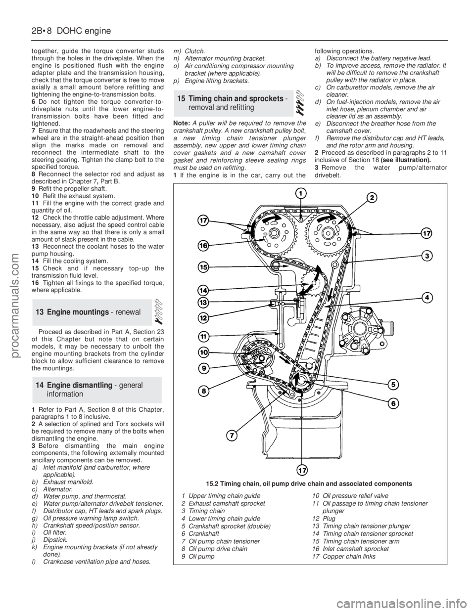
2Proceed as described in paragraphs 2 to 11
inclusive of Section 18 (see illustration).
3Remove the water pump/alternator
drivebelt.
15Timing chain and sprockets -
removal and refitting
14Engine dismantling - general
information
13Engine mountings - renewal
2B•8DOHCengine
1 Upper timing chain guide
2 Exhaust camshaft sprocket
3 Timing chain
4 Lower timing chain guide
5 Crankshaft sprocket (double)
6 Crankshaft
7 Oil pump chain tensioner
8 Oil pump drive chain
9 Oil pump10 Oil pressure relief valve
11 Oil passage to timing chain tensioner
plunger
12 Plug
13 Timing chain tensioner plunger
14 Timing chain tensioner sprocket
15 Timing chain tensioner arm
16 Inlet camshaft sprocket
17 Copper chain links
15.2 Timing chain, oil pump drive chain and associated components
procarmanuals.com
Page 140 of 255
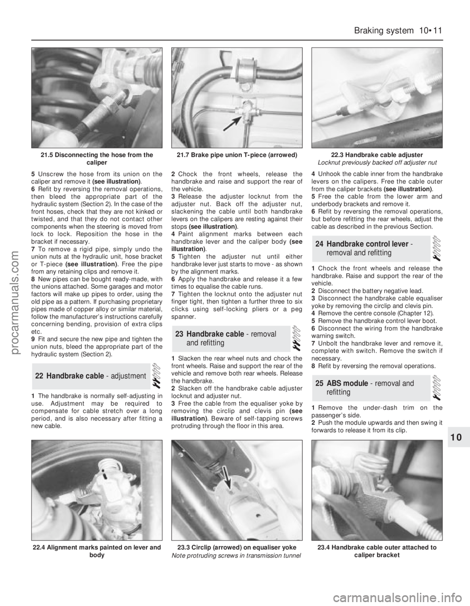
5Unscrew the hose from its union on the
caliper and remove it (see illustration).
6Refit by reversing the removal operations,
then bleed the appropriate part of the
hydraulic system (Section 2). In the case of the
front hoses, check that they are not kinked or
twisted, and that they do not contact other
components when the steering is moved from
lock to lock. Reposition the hose in the
bracket if necessary.
7To remove a rigid pipe, simply undo the
union nuts at the hydraulic unit, hose bracket
or T-piece (see illustration). Free the pipe
from any retaining clips and remove it.
8New pipes can be bought ready-made, with
the unions attached. Some garages and motor
factors will make up pipes to order, using the
old pipe as a pattern. If purchasing proprietary
pipes made of copper alloy or similar material,
follow the manufacturer’s instructions carefully
concerning bending, provision of extra clips
etc.
9Fit and secure the new pipe and tighten the
union nuts, bleed the appropriate part of the
hydraulic system (Section 2).
1The handbrake is normally self-adjusting in
use. Adjustment may be required to
compensate for cable stretch over a long
period, and is also necessary after fitting a
new cable.2Chock the front wheels, release the
handbrake and raise and support the rear of
the vehicle.
3Release the adjuster locknut from the
adjuster nut. Back off the adjuster nut,
slackening the cable until both handbrake
levers on the calipers are resting against their
stops (see illustration).
4Paint alignment marks between each
handbrake lever and the caliper body (see
illustration).
5Tighten the adjuster nut until either
handbrake lever just starts to move - as shown
by the alignment marks.
6Apply the handbrake and release it a few
times to equalise the cable runs.
7Tighten the locknut onto the adjuster nut
finger tight, then tighten a further three to six
clicks using self-locking pliers or a peg
spanner.
1Slacken the rear wheel nuts and chock the
front wheels. Raise and support the rear of the
vehicle and remove both rear wheels. Release
the handbrake.
2Slacken off the handbrake cable adjuster
locknut and adjuster nut.
3Free the cable from the equaliser yoke by
removing the circlip and clevis pin (see
illustration). Beware of self-tapping screws
protruding through the floor in this area.4Unhook the cable inner from the handbrake
levers on the calipers. Free the cable outer
from the caliper brackets (see illustration).
5Free the cable from the lower arm and
underbody brackets and remove it.
6Refit by reversing the removal operations,
but before refitting the rear wheels, adjust the
cable as described in the previous Section.
1Chock the front wheels and release the
handbrake. Raise and support the rear of the
vehicle.
2Disconnect the battery negative lead.
3Disconnect the handbrake cable equaliser
yoke by removing the circlip and clevis pin.
4Remove the centre console (Chapter 12).
5Remove the handbrake control lever boot.
6Disconnect the wiring from the handbrake
warning switch.
7Unbolt the handbrake lever and remove it,
complete with switch. Remove the switch if
necessary.
8Refit by reversing the removal operations.
1Remove the under-dash trim on the
passenger’s side.
2Push the module upwards and then swing it
forwards to release it from its clip.
25ABS module - removal and
refitting
24Handbrake control lever -
removal and refitting
23Handbrake cable - removal
and refitting
22Handbrake cable - adjustment
Braking system 10•11
10
21.5 Disconnecting the hose from the
caliper21.7 Brake pipe union T-piece (arrowed)22.3 Handbrake cable adjuster
Locknut previously backed off adjuster nut
22.4 Alignment marks painted on lever and
body23.3 Circlip (arrowed) on equaliser yoke
Note protruding screws in transmission tunnel23.4 Handbrake cable outer attached to
caliper bracket
procarmanuals.com
Page 146 of 255
The steering gear is of rack-and-pinion type.
Power assistance is standard on V6 models
and optional on others. The power-assisted
steering gear has a “variable ratio” effect
which increases the steering ratio about the
straight-ahead position: this provides quick
lock-to-lock action without the penalty of
over-responsiveness in open road driving.
The steering wheel is adjustable both up-
and-down and fore-and-aft. Both steering
column and shaft are designed to collapse
under impact. The steering shaft is connected
to the pinion by an intermediate shaft, which
has a universal joint at its upper end and a
flexible coupling at the lower end.
Front suspension is independent, of the
MacPherson strut type, with coil springs and
concentric telescopic shock absorbers. The
struts are attached to the tops of the stub axle
carriers, which are located at their lower ends
by balljoints incorporated in the lower
suspension arms. The lower suspension arms
pivot at their inner ends, where they are
attached to a central crossmember. The anti-
roll bar is attached to the rear of the arms and
serves to control fore-and-aft movement as
well as reducing roll.
Suspension geometry has been designed to
give good steering “feel”, resistance to pulling
caused by uneven braking effort or tyre
deflation, and (in the case of manual steering)
acceptably low steering wheel effort at parking
speeds. Only toe is adjustable in service.
The rear suspension is also independent. It
is of the semi-trailing arm type, with coil
springs and separate telescopic shock
absorbers. An optionally-available ride height
control system keeps the rear suspension
height constant, regardless of vehicle load.
Both front and rear wheel bearings are of a
special taper-roller type and require no
periodic adjustment in service.1Refer to Chapter 1, Section 35, to check the
power steering fluid level.
2If the fluid level falls so low that air enters
the pump, or after component renewal, the
system must be bled as follows.
3Remove the reservoir filler cap. Top-up with
clean fluid to the appropriate “cold” level. It is
important that the fluid is free of air bubbles,
so do not shake the container when topping-
up, and pour the fluid slowly.
4Disconnect the negative LT lead from the
ignition coil. Have an assistant crank the
engine on the starter in two second bursts, at
the same time turning the steering wheel from
lock to lock. Keep the reservoir topped up
whilst this is going on.
5When air bubbles no longer appear in the
fluid, stop the cranking. Reconnect the coil
negative lead and run the engine for a few
seconds, then stop it and check the level
again. Refit the filler cap.
6Run the vehicle for a few miles to warm up
the fluid and expel any remaining air, then stop
the engine and make a final fluid level check.
Manual steering
1Position the steering in the straight-ahead
position, then remove the ignition key so that
the steering is locked.
2Slacken the front wheel nuts. Raise and
support the front of the vehicle and remove
the front wheels.
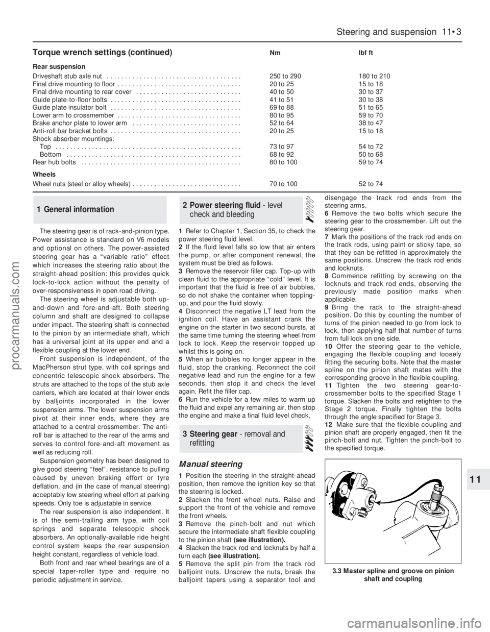
3Remove the pinch-bolt and nut which
secure the intermediate shaft flexible coupling
to the pinion shaft (see illustration).
4Slacken the track rod end locknuts by half a
turn each (see illustration).
5Remove the split pin from the track rod
balljoint nuts. Unscrew the nuts, break the
balljoint tapers using a separator tool anddisengage the track rod ends from the
steering arms.
6Remove the two bolts which secure the
steering gear to the crossmember. Lift out the
steering gear.
7Mark the positions of the track rod ends on
the track rods, using paint or sticky tape, so
that they can be refitted in approximately the
same positions. Unscrew the track rod ends
and locknuts.
8Commence refitting by screwing on the
locknuts and track rod ends, observing the
previously made position marks when
applicable.
9Bring the rack to the straight-ahead
position. Do this by counting the number of
turns of the pinion needed to go from lock to
lock, then applying half that number of turns
from full lock on one side.
10Offer the steering gear to the vehicle,
engaging the flexible coupling and loosely
fitting the securing bolts. Note that the master
spline on the pinion shaft mates with the
corresponding groove in the flexible coupling.
11Tighten the two steering gear-to-
crossmember bolts to the specified Stage 1
torque. Slacken the bolts and retighten to the
Stage 2 torque. Finally tighten the bolts
through the angle specified for Stage 3.
12Make sure that the flexible coupling and
pinion shaft are properly engaged, then fit the
pinch-bolt and nut. Tighten the pinch-bolt to
the specified torque.
3Steering gear - removal and
refitting
2Power steering fluid - level
check and bleeding1General information
Steering and suspension 11•3
11
3.3 Master spline and groove on pinion
shaft and coupling
Torque wrench settings (continued)Nmlbf ft
Rear suspension
Driveshaft stub axle nut . . . . . . . . . . . . . . . . . . . . . . . . . . . . . . . . . . . . .250 to 290180 to 210
Final drive mounting to floor . . . . . . . . . . . . . . . . . . . . . . . . . . . . . . . . . .20 to 2515 to 18
Final drive mounting to rear cover . . . . . . . . . . . . . . . . . . . . . . . . . . . . .40 to 5030 to 37
Guide plate-to-floor bolts . . . . . . . . . . . . . . . . . . . . . . . . . . . . . . . . . . . .41 to 5130 to 38
Guide plate insulator bolt . . . . . . . . . . . . . . . . . . . . . . . . . . . . . . . . . . . .69 to 8851 to 65
Lower arm to crossmember . . . . . . . . . . . . . . . . . . . . . . . . . . . . . . . . . .80 to 9559 to 70
Brake anchor plate to lower arm . . . . . . . . . . . . . . . . . . . . . . . . . . . . . .52 to 6438 to 47
Anti-roll bar bracket bolts . . . . . . . . . . . . . . . . . . . . . . . . . . . . . . . . . . . .20 to 2515 to 18
Shock absorber mountings:
Top . . . . . . . . . . . . . . . . . . . . . . . . . . . . . . . . . . . . . . . . . . . . . . . . . . .73 to 9754 to 72
Bottom . . . . . . . . . . . . . . . . . . . . . . . . . . . . . . . . . . . . . . . . . . . . . . . .68 to 9250 to 68
Rear hub bolts . . . . . . . . . . . . . . . . . . . . . . . . . . . . . . . . . . . . . . . . . . . .80 to 10059 to 74
Wheels
Wheel nuts (steel or alloy wheels) . . . . . . . . . . . . . . . . . . . . . . . . . . . . . .70 to 10052 to 74
procarmanuals.com
Page 148 of 255
reference to horn switch plate retaining
screws. Note that the wheel is retained by a
bolt, not a nut as on earlier models. To gain
access to the bolt, prise out the horn button
and disconnect the wiring connectors.
1This operation is for correcting small errors
in steering wheel centralisation - up to 60°. For
larger errors, remove the steering wheel and
make a rough correction by repositioning the
wheel on refitting.
2Drive the vehicle in a straight line on a level
surface. Note the angle by which the steering
wheel deviates from the desired straight-
ahead position.
3Raise the front of the vehicle by driving it
onto ramps, or with a jack and axle stands
(see “Jacking”).
4Slacken both track rod end locknuts. Also
slacken the steering rack bellows outer clips.
5Make alignment marks between each track
rod end and its rod, so that the amount of
rotation applied can be accurately determined.
6Turn both track rodsin the same direction
to correct the steering wheel position. As a
rough guide, 19°of track rod rotation will
change the steering wheel position by 1°. To
correct error at the steering wheel, rotate both
track rods anti-clockwise (viewed from the
left-hand side of the vehicle), and the reverse
to correct as anti-clockwise errors. Both track
rods must be rotated by the same amount.
7Tighten the bellows clips and the track rod
end locknuts when adjustment is correct.
Lower the vehicle.
1Disconnect the battery negative lead.
2Position the steering in the straight-ahead
position.
3Remove the steering wheel. This is not
essential, but will improve access.
4Working under the bonnet, disconnect the
intermediate shaft universal joint from the
steering column shaft.5Remove the steering column shrouds and
disconnect the switch multi-plugs. Do not
forget the ignition/starter switch.
6Disconnect the bonnet release cable from the
operating lever on the underside of the column.
7Prise out the driver’s side air vent. Remove
the under-dash insulation and trim panel on
the driver’s side, unclipping the bulb failure
module, where applicable.
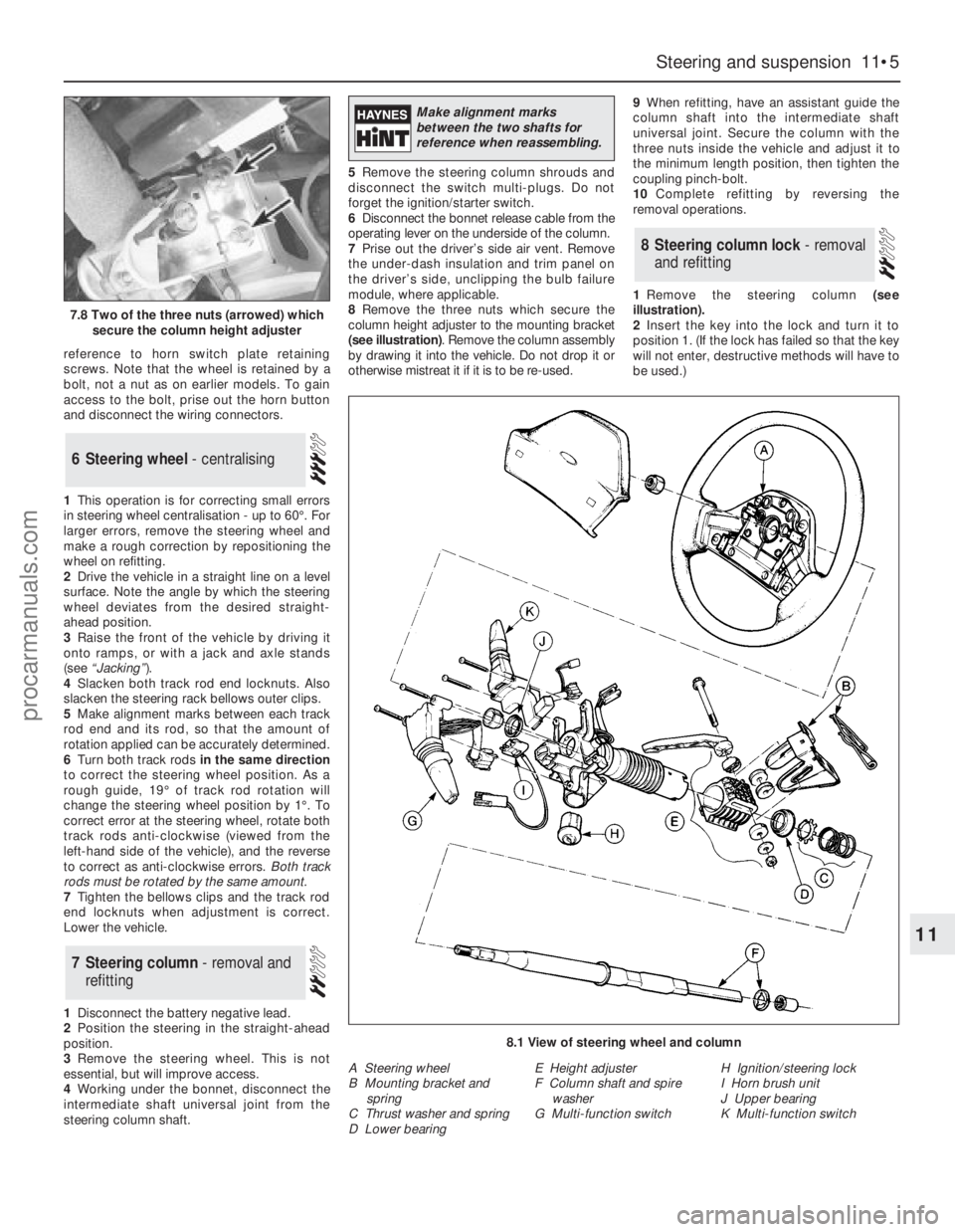
8Remove the three nuts which secure the
column height adjuster to the mounting bracket
(see illustration). Remove the column assembly
by drawing it into the vehicle. Do not drop it or
otherwise mistreat it if it is to be re-used.9When refitting, have an assistant guide the
column shaft into the intermediate shaft
universal joint. Secure the column with the
three nuts inside the vehicle and adjust it to
the minimum length position, then tighten the
coupling pinch-bolt.
10Complete refitting by reversing the
removal operations.
1Remove the steering column (see
illustration).
2Insert the key into the lock and turn it to
position 1. (If the lock has failed so that the key
will not enter, destructive methods will have to
be used.)
8Steering column lock - removal
and refitting
7Steering column - removal and
refitting
6Steering wheel - centralising
Steering and suspension 11•5
11
7.8 Two of the three nuts (arrowed) which
secure the column height adjuster
8.1 View of steering wheel and column
A Steering wheel
B Mounting bracket and
spring
C Thrust washer and spring
D Lower bearingE Height adjuster
F Column shaft and spire
washer
G Multi-function switchH Ignition/steering lock
I Horn brush unit
J Upper bearing
K Multi-function switch
Make alignment marks
between the two shafts for
reference when reassembling.
procarmanuals.com
Page 149 of 255
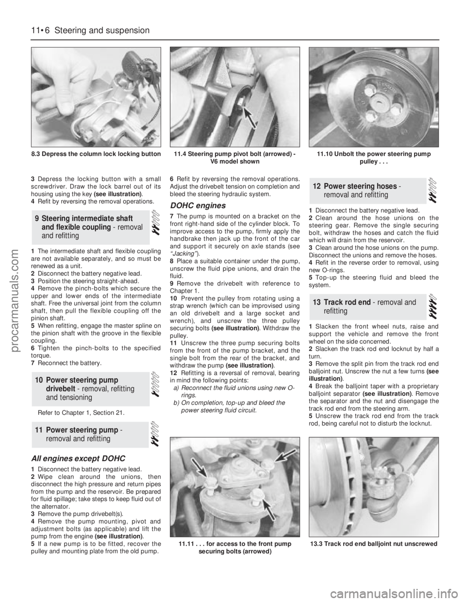
3Depress the locking button with a small
screwdriver. Draw the lock barrel out of its
housing using the key (see illustration).
4Refit by reversing the removal operations.
1The intermediate shaft and flexible coupling
are not available separately, and so must be
renewed as a unit.
2Disconnect the battery negative lead.
3Position the steering straight-ahead.
4Remove the pinch-bolts which secure the
upper and lower ends of the intermediate
shaft. Free the universal joint from the column
shaft, then pull the flexible coupling off the
pinion shaft.
5When refitting, engage the master spline on
the pinion shaft with the groove in the flexible
coupling.
6Tighten the pinch-bolts to the specified
torque.
7Reconnect the battery.
Refer to Chapter 1, Section 21.
All engines except DOHC
1Disconnect the battery negative lead.
2Wipe clean around the unions, then
disconnect the high pressure and return pipes
from the pump and the reservoir. Be prepared
for fluid spillage; take steps to keep fluid out of
the alternator.
3Remove the pump drivebelt(s).
4Remove the pump mounting, pivot and
adjustment bolts (as applicable) and lift the
pump from the engine (see illustration).
5If a new pump is to be fitted, recover the
pulley and mounting plate from the old pump.6Refit by reversing the removal operations.
Adjust the drivebelt tension on completion and
bleed the steering hydraulic system.
DOHC engines
7The pump is mounted on a bracket on the
front right-hand side of the cylinder block. To
improve access to the pump, firmly apply the
handbrake then jack up the front of the car
and support it securely on axle stands (see
“Jacking”).
8Place a suitable container under the pump,
unscrew the fluid pipe unions, and drain the
fluid.
9Remove the drivebelt with reference to
Chapter 1.
10Prevent the pulley from rotating using a
strap wrench (which can be improvised using
an old drivebelt and a large socket and
wrench), and unscrew the three pulley
securing bolts (see illustration). Withdraw the
pulley.
11Unscrew the three pump securing bolts
from the front of the pump bracket, and the
single bolt from the rear of the bracket, and
withdraw the pump (see illustration).
12Refitting is a reversal of removal, bearing
in mind the following points:
a)Reconnect the fluid unions using new O-
rings.
b)On completion, top-up and bleed the
power steering fluid circuit.1Disconnect the battery negative lead.
2Clean around the hose unions on the
steering gear. Remove the single securing
bolt, withdraw the hoses and catch the fluid
which will drain from the reservoir.
3Clean around the hose unions on the pump.
Disconnect the unions and remove the hoses.
4Refit in the reverse order to removal, using
new O-rings.
5Top-up the steering fluid and bleed the
system.
1Slacken the front wheel nuts, raise and
support the vehicle and remove the front
wheel on the side concerned.
2Slacken the track rod end locknut by half a
turn.
3Remove the split pin from the track rod end
balljoint nut. Unscrew the nut a few turns (see
illustration).
4Break the balljoint taper with a proprietary
balljoint separator (see illustration). Remove
the separator and the nut and disengage the
track rod end from the steering arm.
5Unscrew the track rod end from the track
rod, being careful not to disturb the locknut.
13Track rod end - removal and
refitting
12Power steering hoses -
removal and refitting
11Power steering pump -
removal and refitting
10Power steering pump
drivebelt - removal, refitting
and tensioning
9Steering intermediate shaft
and flexible coupling - removal
and refitting
11•6Steering and suspension
8.3 Depress the column lock locking button
11.11 . . . for access to the front pump
securing bolts (arrowed)13.3 Track rod end balljoint nut unscrewed
11.4 Steering pump pivot bolt (arrowed) -
V6 model shown11.10 Unbolt the power steering pump
pulley . . .
procarmanuals.com
Page 150 of 255
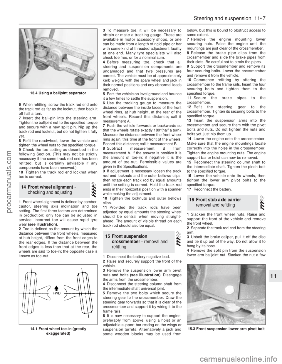
6When refitting, screw the track rod end onto
the track rod as far as the locknut, then back it
off half a turn.
7Insert the ball-pin into the steering arm.
Tighten the balljoint nut to the specified torque
and secure with a new split pin. Nip up the
track rod end locknut, but do not tighten it fully
yet.
8Refit the roadwheel, lower the vehicle and
tighten the wheel nuts to the specified torque.
9Check the toe setting as described in the
following Section. (This may not be strictly
necessary if the same track rod end has been
refitted, but is certainly advisable if any
components have been renewed.)
10Tighten the track rod end locknut when
toe is correct.
1Front wheel alignment is defined by camber,
castor, steering axis inclination and toe
setting. The first three factors are determined
in production; only toe can be adjusted in
service. Incorrect toe will cause rapid tyre
wear (see illustration).
2Toe is defined as the amount by which the
distance between the front wheels, measured
at hub height, differs from the front edges to
the rear edges. If the distance between the
front edges is less than that at the rear, the
wheels are said to toe-in; the opposite case is
known as toe-out.3To measure toe, it will be necessary to
obtain or make a tracking gauge. These are
available in motor accessory shops, or one
can be made from a length of rigid pipe or bar
with some kind of threaded adjustment facility
at one end. Many tyre specialists will also
check toe free, or for a nominal sum.
4Before measuring toe, check that all
steering and suspension components are
undamaged and that tyre pressures are
correct. The vehicle must be at approximately
kerb weight, with the spare wheel and jack in
their normal positions and any abnormal loads
removed.
5Park the vehicle on level ground and bounce
it a few times to settle the suspension.
6Use the tracking gauge to measure the
distance between the inside faces of the front
wheel rims, at hub height, at the rear of the
front wheels. Record this distance; call it
measurement A.
7Push the vehicle forwards or backwards so
that the wheels rotate exactly 180°(half a turn).
Measure the distance between the front wheel
rims again, this time at the front of the wheels.
Record this distance; call it measurement B.
8Subtract measurement B from
measurement A. If the answer is positive it is
the amount of toe-in; if negative it is the
amount of toe-out. Permissible values are
given in the Specifications.
9If adjustment is necessary loosen the track
rod end locknuts and the outer bellows clips,
then rotate each track rod by equal amounts
until the setting is correct. Hold the track rod
ends in their horizontal position with a spanner
while making the adjustment.
10Tighten the locknuts and outer bellows
clips.
11Provided the track rods have been
adjusted by equal amounts the steering wheel
should be central when moving straight-
ahead. The amount of visible thread on each
track rod should also be equal.
1Disconnect the battery negative lead.
2Raise and securely support the front of the
vehicle.
3Remove the suspension lower arm pivot
nuts and bolts (see illustration). Disengage
the arms from the crossmember.
4Disconnect the steering column shaft from
the intermediate shaft universal joint.
5Remove the two bolts which secure the
steering gear to the crossmember. Draw the
steering gear forwards so that it is clear of the
crossmember and support it by wiring it to the
frame rails.
6It is now necessary to support the engine,
preferably from above, using a hoist or an
adjustable support bar resting on the wings or
suspension turrets. Alternatively a jack and
some wooden blocks may be used frombelow, but this is bound to obstruct access to
some extent.
7Remove the engine mounting lower
securing nuts. Raise the engine until the
mountings are just clear of the crossmember.
8Release the brake pipe clips from the
crossmember and slide the brake pipes from
their slots. Be careful not to strain the pipes.
9Support the crossmember and remove its
four securing bolts. Lower the crossmember
and remove it from the vehicle.
10Commence refitting by offering the
crossmember to the frame rails. Insert the four
securing bolts and tighten them to the
specified torque.
11Secure the brake pipes to the
crossmember.
12Refit the steering gear to the
crossmember. Tighten its securing bolts to the
specified torque.
13Insert the suspension arms into the
crossmember and secure them with the pivot
bolts and nuts. Do not tighten the nuts and
bolts yet, just nip them up.
14Lower the engine onto the crossmember.
Make sure that the engine mountings locate
correctly into the holes in the crossmember.
Tighten the engine mounting nuts. The engine
support bar or hoist can now be removed.
15Reconnect the steering column shaft to
the intermediate shaft. Tighten the pinch-bolt
to the specified torque.
16Lower the vehicle onto its wheels, then
tighten the lower arm pivot bolts to the
specified torque.
17Reconnect the battery.
1Slacken the front wheel nuts. Raise and
support the front of the vehicle and remove
the front wheel.
2Separate the track rod end from the steering
arm.
3Unbolt the brake caliper, pull it off the disc
and tie it up out of the way. Do not allow it to
hang by its hose.
4Remove the split pin from the suspension
lower arm balljoint nut. Slacken the nut a few
16Front stub axle carrier -
removal and refitting
15Front suspension
crossmember - removal and
refitting
14Front wheel alignment -
checking and adjusting
Steering and suspension 11•7
11
13.4 Using a balljoint separator
14.1 Front wheel toe-in (greatly
exaggerated)15.3 Front suspension lower arm pivot bolt
procarmanuals.com
Page 151 of 255
times, then use a proprietary balljoint
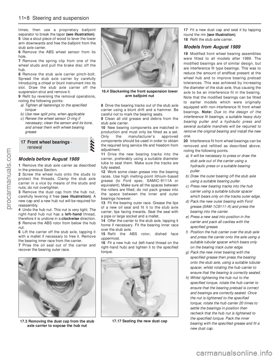
separator to break the taper (see illustration).
5Use a stout piece of wood to lever the lower
arm downwards and free the balljoint from the
stub axle carrier.
6Remove the ABS wheel sensor from its
hole.
7Remove the spring clip from one of the
wheel studs and pull the brake disc off the
hub.
8Remove the stub axle carrier pinch-bolt.
Spread the stub axle carrier by carefully
introducing a chisel or blunt instrument into its
slot. Draw the stub axle carrier off the
suspension strut and remove it.
9Refit by reversing the removal operations,
noting the following points:
a)Tighten all fastenings to the specified
torque
b)Use new split pins, when applicable
c)Renew the wheel sensor O-ring if
necessary; clean the sensor and its bore,
and smear them with wheel bearing
grease
Models before August 1989
1Remove the stub axle carrier as described
in the previous Section.
2Screw the wheel nuts onto the studs to
protect the threads. Clamp the stub axle
carrier in a vice by means of the studs and
nuts; do not overtighten.
3Remove the dust cap from the hub nut,
carefully levering it free (see illustration). A
new cap and a new hub nut will be required for
reassembly.
4Undo the hub nut. This nut is very tight. The
right-hand hub nut has a left-handthread,
therefore it is undone in a clockwisedirection.
5Remove the ABS rotor from below the hub
nut.
6Lift the carrier off the stub axle, tapping it
with a mallet if necessary to free it. Remove
the bearing inner race from the carrier.
7Prise the oil seal out of the carrier and
recover the bearing outer race.8Drive the bearing tracks out of the stub axle
carrier using a blunt drift and a hammer. Be
careful not to mark the bearing seats.
9Clean all old grease and debris from the
stub axle carrier.
10New bearing components are matched in
production and must only be fitted as a set.
Only the manufacturer’s approved
components should be used in order to obtain
the required long service life and freedom from
adjustment.
11Drive the new bearing tracks into the
carrier, preferably using a suitable diameter
tube to seat them. Make sure the tracks are
fully seated.
12Work some clean grease into the bearing
races. Use high melting-point lithium-based
grease (to Ford spec. SAMIC-9111A or
equivalent). Make sure all the spaces between
the rollers are filled; do not pack grease into
the space between the inner and outer
bearings however.
13Fit the bearing outer race. Grease the lips
of a new oil seal and fit it to the stub axle
carrier, lips facing inwards. Seat the seal with
a pipe or large socket and a mallet.
14Offer the carrier to the stub axle, tapping it
home if necessary. Fit the bearing inner race
over the stub axle.
15Refit the ABS rotor, dished face
uppermost.
16Fit a new hub nut (left-hand thread on the
right-hand hub) and tighten it to the specified
torque.17Fit a new dust cap and seat it by tapping
round the rim (see illustration).
18Refit the stub axle carrier.
Models from August 1989
19Modified front wheel bearing assemblies
were fitted to all models after 1989. The
modified bearings are of similar design, but
are interference fit type bearings. This was to
reduce the amount of endfloat present at the
wheel hub and to improve bearing preload
tolerances. This was achieved by increasing
the diameter of the stub axle, thus causing the
axle to be an interference fit in the bearing.
Note that the modified bearings can be fitted
to earlier models which were originally
equipped with non-interference fit front wheel
bearings. Note: Due to the design of the
interference fit bearings, a suitable heavy duty
bearing puller and a hydraulic press and
several suitable mandrels will be required to
remove the originalbearing and install the new
one.
20Interference fit front wheel bearings can be
removed and refitted as described above,
noting the following points.
a)It will be necessary to press or draw the
stub axle out of the carrier using a
hydraulic press or a suitable bearing
puller.
b)Draw the outer bearing off the stub axle
using a suitable bearing puller.
c)Press new bearing tracks into the hub
carrier using a suitable tubular spacer
which bears only on the tracks outer edge.
d)Pack the new outer bearing with Ford
grease (SAM-1C9111-A) and press the
bearing into the carrier.
e)Press a new seal into position in the
carrier and pack all cavities with the
specified grease.
f)Position the hub carrier over the stub axle
and press the carrier onto the axle using a
suitable tubular spacer which bears only
on the bearing track outer edge.
g)Pack the new inner bearing with the
specified grease then press the bearing
onto the stub axle, using a suitable tubular
spacer, whilst rotating the hub carrier to
ensure that the bearing is correctly seated.
h)Whilst tightening the hub nut to the
specified torque, rotate the hub carrier to
ensure that the bearing preload is correct
and bearings are correctly seated. Once
the nut is tightened to the specified
torque, rotate the hub carrier 20 times to
settle the bearings in position then
recheck that the hub nut is tightened to
the specified torque. Pack the inner
bearing with the specified grease and fit a
new dust cap.
17Front wheel bearings -
renewal
11•8Steering and suspension
16.4 Slackening the front suspension lower
arm balljoint nut
17.17 Seating the new dust cap17.3 Removing the dust cap from the stub
axle carrier to expose the hub nut
procarmanuals.com