Aux FORD KUGA 2010 1.G Owners Manual
[x] Cancel search | Manufacturer: FORD, Model Year: 2010, Model line: KUGA, Model: FORD KUGA 2010 1.GPages: 226, PDF Size: 8.07 MB
Page 4 of 226
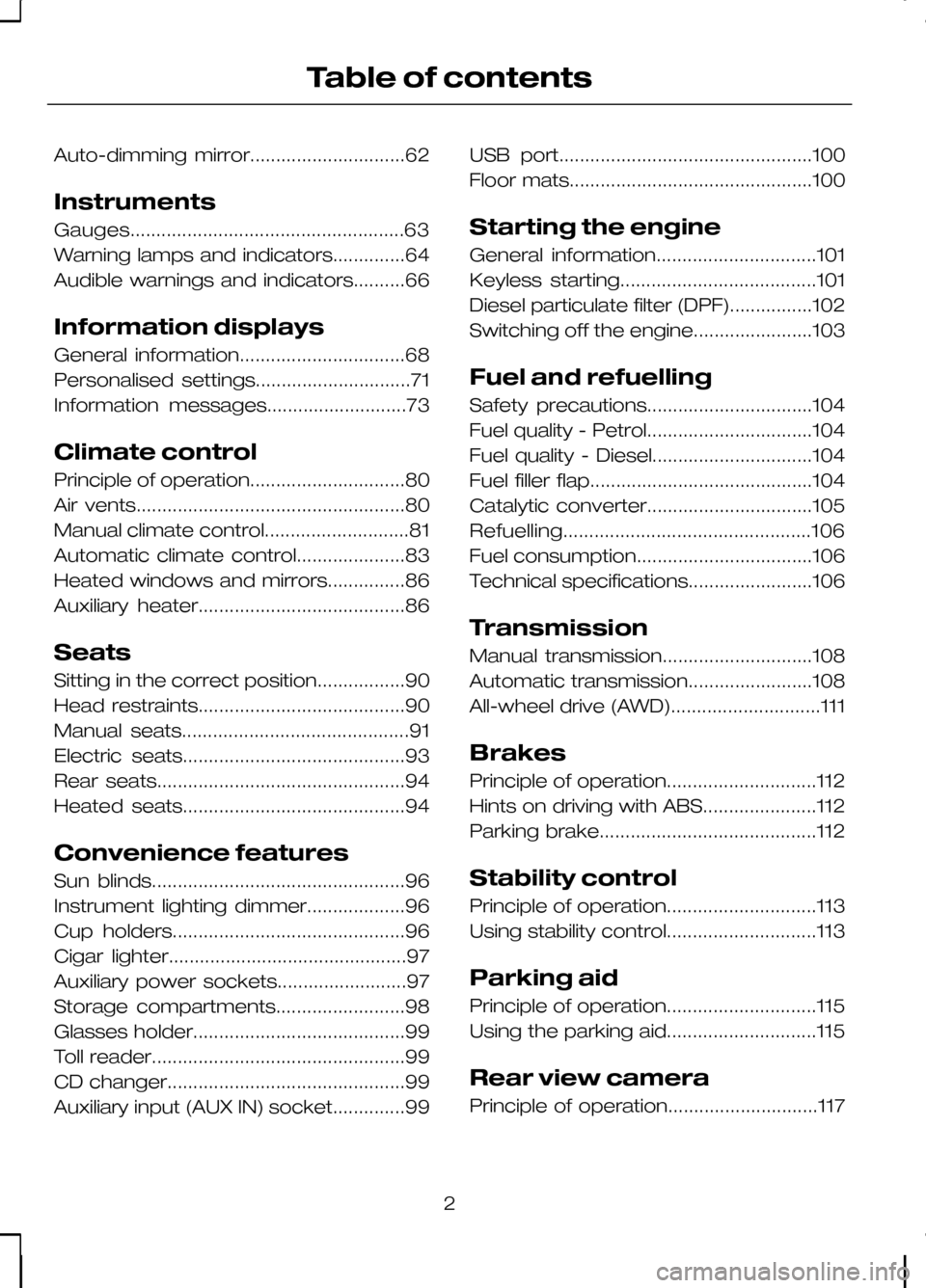
Auto-dimming mirror..............................62
Instruments
Gauges.....................................................63
Warning lamps and indicators..............64
Audible warnings and indicators..........66
Information displays
General information................................68
Personalised settings..............................71
Information messages...........................73
Climate control
Principle of operation..............................80
Air vents....................................................80
Manual climate control............................81
Automatic climate control.....................83
Heated windows and mirrors...............86
Auxiliary heater........................................86
Seats
Sitting in the correct position.................90
Head restraints........................................90
Manual seats............................................91
Electric seats...........................................93
Rear seats................................................94
Heated seats...........................................94
Convenience features
Sun blinds.................................................96
Instrument lighting dimmer...................96
Cup holders.............................................96
Cigar lighter..............................................97
Auxiliary power sockets.........................97
Storage compartments.........................98
Glasses holder.........................................99
Toll reader.................................................99
CD changer..............................................99
Auxiliary input (AUX IN) socket..............99
USB port.................................................100
Floor mats...............................................100
Starting the engine
General information...............................101
Keyless starting......................................101
Diesel particulate filter (DPF)................102
Switching off the engine.......................103
Fuel and refuelling
Safety precautions................................104
Fuel quality - Petrol................................104
Fuel quality - Diesel...............................104
Fuel filler flap...........................................104
Catalytic converter................................105
Refuelling................................................106
Fuel consumption..................................106
Technical specifications........................106
Transmission
Manual transmission.............................108
Automatic transmission........................108
All-wheel drive (AWD).............................111
Brakes
Principle of operation.............................112
Hints on driving with ABS......................112
Parking brake..........................................112
Stability control
Principle of operation.............................113
Using stability control.............................113
Parking aid
Principle of operation.............................115
Using the parking aid.............................115
Rear view camera
Principle of operation.............................117
2
Table of contents
Page 72 of 226
70
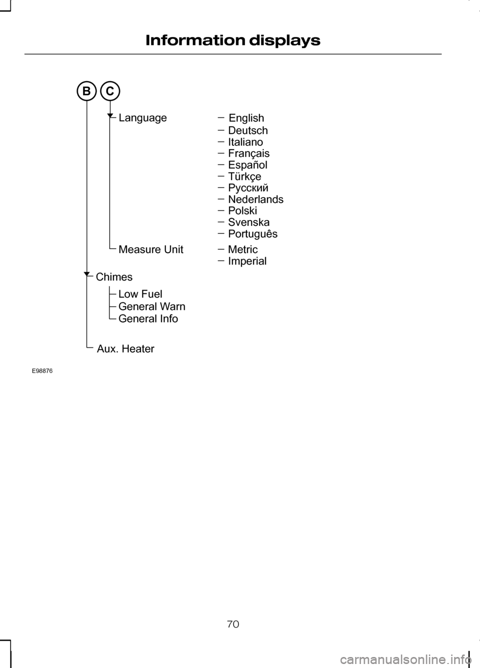
Information displaysBCE98876EnglishLanguageMeasureUnitDeutschItalianoFrançaisEspañolTürkçePyccкийNederlandsPolskiSvenskaPortuguêsMetricImperialChimesAux.HeaterLowFuelGeneralWarnGeneralInfo
Page 88 of 226
HEATED WINDOWS AND
MIRRORS
Heated windows
Use the heated windows to defrost or
demist the windscreen or rear window.
Note:The heated windows operate only
when the engine is running.
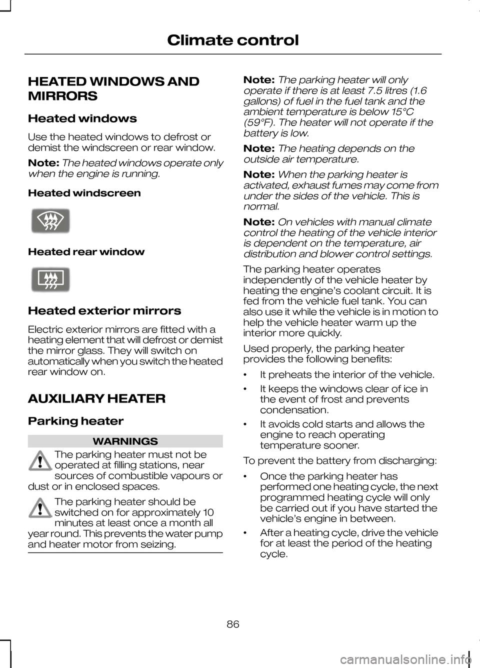
Heated windscreen Heated rear window
Heated exterior mirrors
Electric exterior mirrors are fitted with a
heating element that will defrost or demist
the mirror glass. They will switch on
automatically when you switch the heated
rear window on.
AUXILIARY HEATER
Parking heater
WARNINGS
The parking heater must not be
operated at filling stations, near
sources of combustible vapours or
dust or in enclosed spaces. The parking heater should be
switched on for approximately 10
minutes at least once a month all
year round. This prevents the water pump
and heater motor from seizing. Note:
The parking heater will only
operate if there is at least 7.5 litres (1.6 gallons) of fuel in the fuel tank and theambient temperature is below 15°C(59°F). The heater will not operate if thebattery is low.
Note:The heating depends on the
outside air temperature.
Note:When the parking heater is
activated, exhaust fumes may come from under the sides of the vehicle. This isnormal.
Note:On vehicles with manual climate
control the heating of the vehicle interior is dependent on the temperature, airdistribution and blower control settings.
The parking heater operates
independently of the vehicle heater by
heating the engine’s coolant circuit. It is
fed from the vehicle fuel tank. You can
also use it while the vehicle is in motion to
help the vehicle heater warm up the
interior more quickly.
Used properly, the parking heater
provides the following benefits:
• It preheats the interior of the vehicle.
• It keeps the windows clear of ice in
the event of frost and prevents
condensation.
• It avoids cold starts and allows the
engine to reach operating
temperature sooner.
To prevent the battery from discharging:
• Once the parking heater has
performed one heating cycle, the next
programmed heating cycle will only
be carried out if you have started the
vehicle’s engine in between.
• After a heating cycle, drive the vehicle
for at least the period of the heating
cycle.
86
Climate controlE72506 E72507
Page 91 of 226
To deactivate the heater, highlight
Active
now and press the SET/RESETbutton
again.
Diesel auxiliary heater
(depending on country)
The diesel auxiliary heater (PTC electrical
heater) aids in warming the engine and
the vehicle interior on vehicles with a
diesel engine. It is switched on or off
automatically depending on the outside
air temperature, the coolant temperature
and the alternator load.
Fuel operated heater
(depending on country)
The fuel operated heater aids in warming
the engine and the vehicle interior on
vehicles with a petrol or diesel engine. It
is switched on or off automatically
depending on the outside air temperature
and the coolant temperature, unless you
have deactivated it. When the fuel
operated heater is operating, a message
appears in the information display. See
Information displays (page 68).
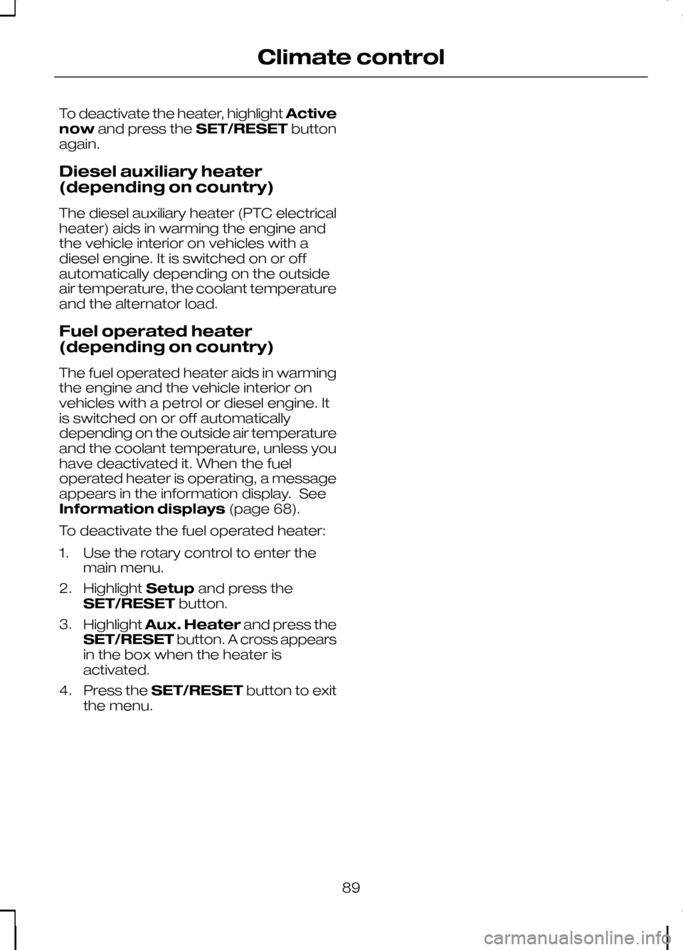
To deactivate the fuel operated heater:
1. Use the rotary control to enter the main menu.
2. Highlight Setupand press the
SET/RESET button.
3. Highlight Aux. Heater and press the
SET/RESET button. A cross appears
in the box when the heater is
activated.
4. Press the SET/RESET button to exit
the menu.
89
Climate control
Page 99 of 226
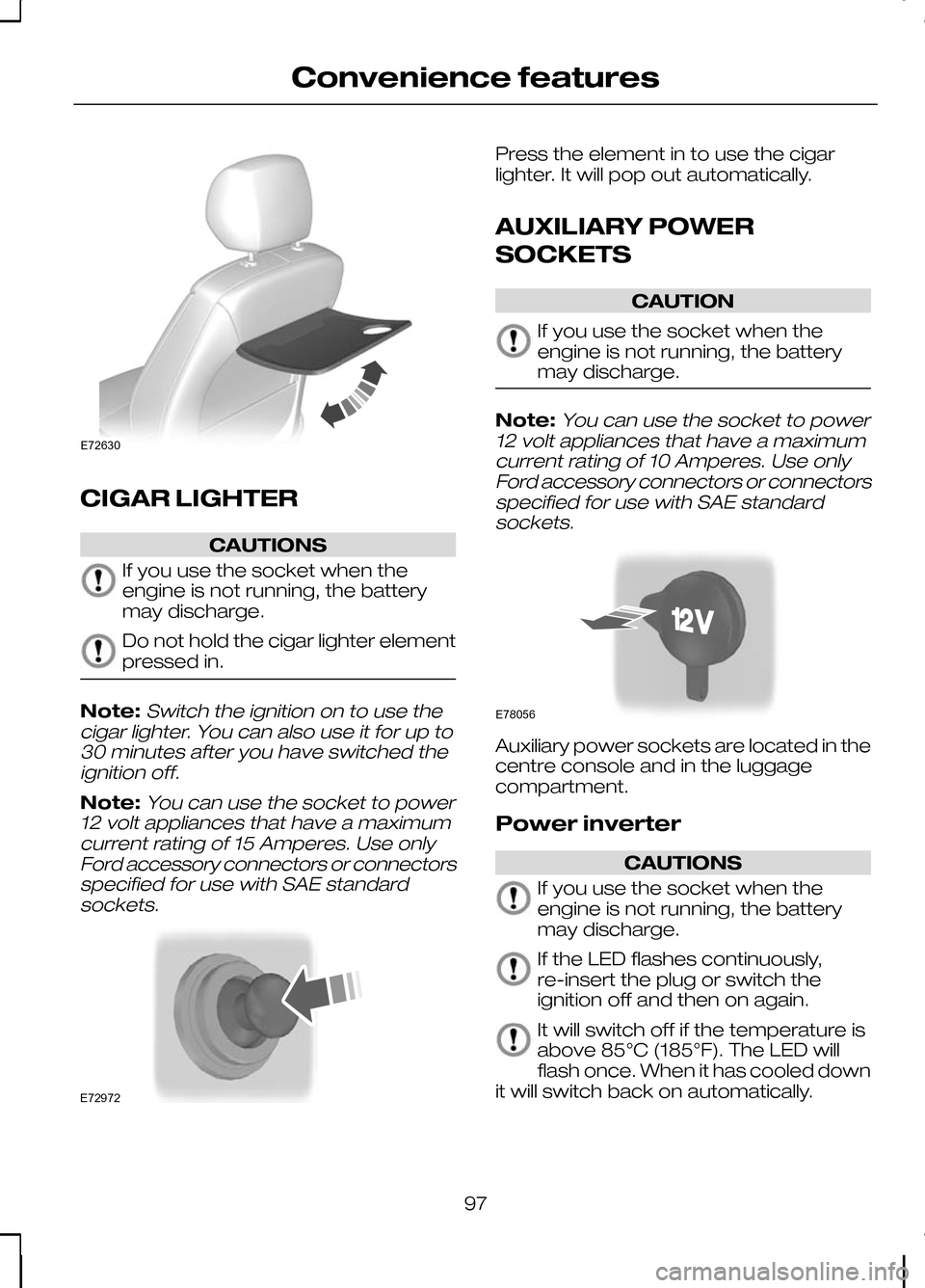
CIGAR LIGHTER
CAUTIONS
If you use the socket when the
engine is not running, the battery
may discharge.
Do not hold the cigar lighter element
pressed in.
Note:Switch the ignition on to use the
cigar lighter. You can also use it for up to 30 minutes after you have switched theignition off.
Note:You can use the socket to power
12 volt appliances that have a maximum current rating of 15 Amperes. Use onlyFord accessory connectors or connectorsspecified for use with SAE standardsockets. Press the element in to use the cigar
lighter. It will pop out automatically.
AUXILIARY POWER
SOCKETS
CAUTION
If you use the socket when the
engine is not running, the battery
may discharge.
Note:
You can use the socket to power
12 volt appliances that have a maximum current rating of 10 Amperes. Use onlyFord accessory connectors or connectorsspecified for use with SAE standardsockets. Auxiliary power sockets are located in the
centre console and in the luggage
compartment.
Power inverter
CAUTIONS
If you use the socket when the
engine is not running, the battery
may discharge.
If the LED flashes continuously,
re-insert the plug or switch the
ignition off and then on again.
It will switch off if the temperature is
above 85°C (185°F). The LED will
flash once. When it has cooled down
it will switch back on automatically.
97
Convenience featuresE72630 E72972 E78056
Page 101 of 226
To gain access to the storage area, fold
up the rear seat cushions. See
Rear
seats (page 94).
Note:Do not overload the storage areas
under the rear seats. Ensure that the rear seat cushions can be folded backcompletely.
GLASSES HOLDER TOLL READER
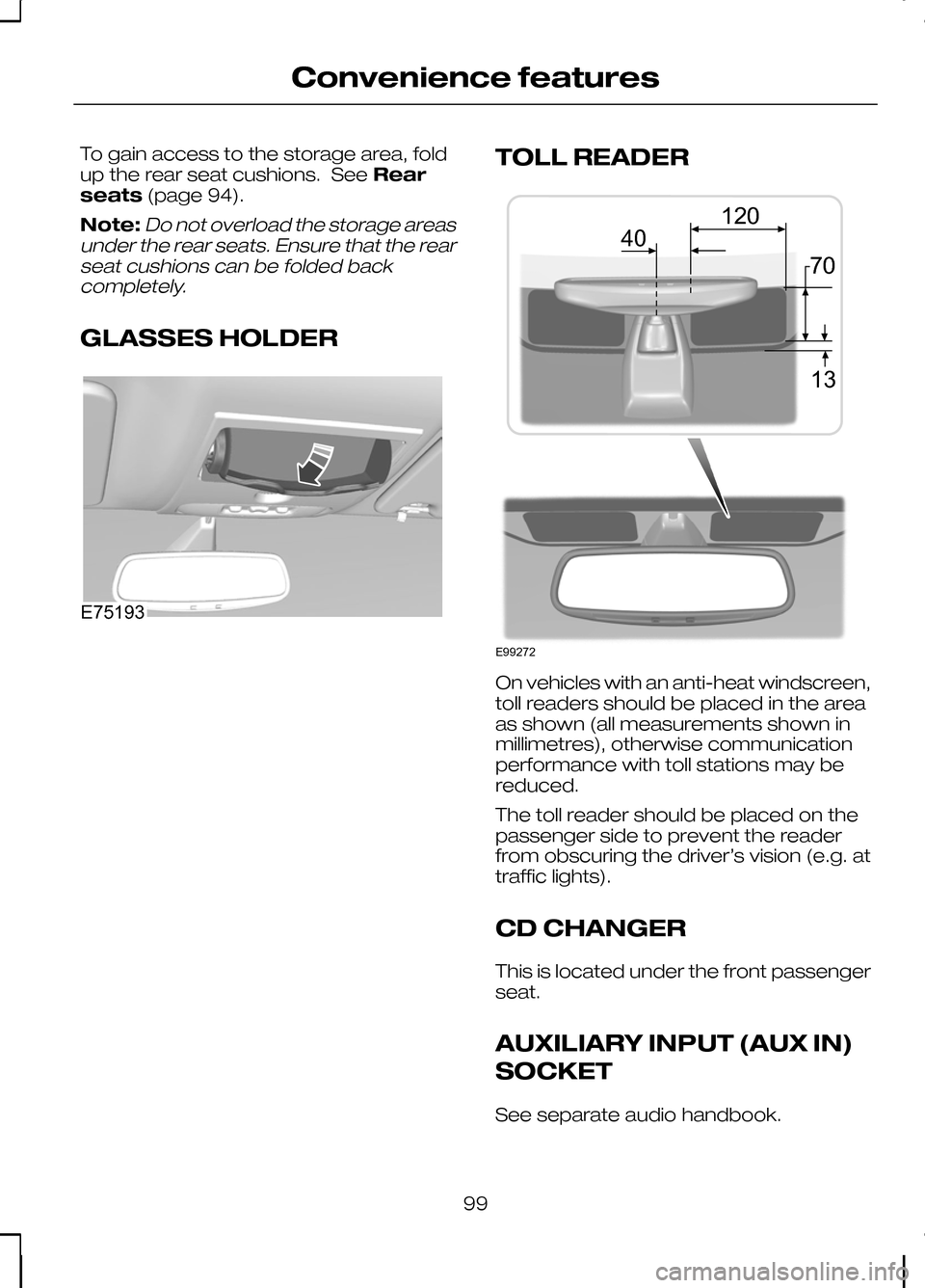
On vehicles with an anti-heat windscreen,
toll readers should be placed in the area
as shown (all measurements shown in
millimetres), otherwise communication
performance with toll stations may be
reduced.
The toll reader should be placed on the
passenger side to prevent the reader
from obscuring the driver’s vision (e.g. at
traffic lights).
CD CHANGER
This is located under the front passenger
seat.
AUXILIARY INPUT (AUX IN)
SOCKET
See separate audio handbook.
99
Convenience featuresE75193 E99272401370120
Page 138 of 226
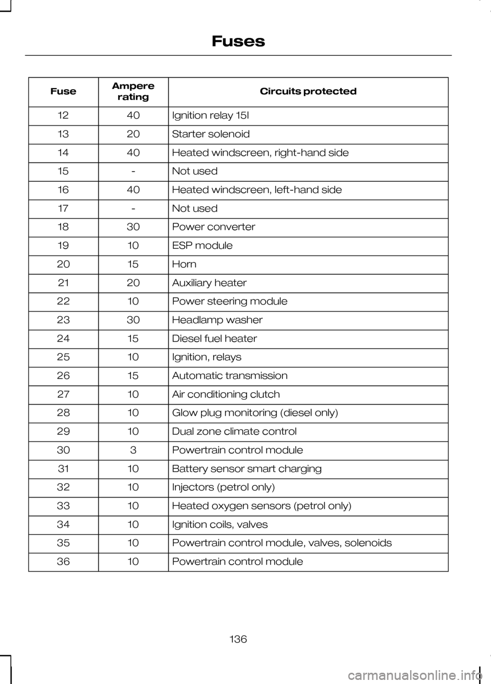
Circuits protected
Ampere
rating
Fuse
Ignition relay 15l
40
12
Starter solenoid
20
13
Heated windscreen, right-hand side
40
14
Not used
-
15
Heated windscreen, left-hand side
40
16
Not used
-
17
Power converter
30
18
ESP module
10
19
Horn
15
20
Auxiliary heater
20
21
Power steering module
10
22
Headlamp washer
30
23
Diesel fuel heater
15
24
Ignition, relays
10
25
Automatic transmission
15
26
Air conditioning clutch
10
27
Glow plug monitoring (diesel only)
10
28
Dual zone climate control
10
29
Powertrain control module
3
30
Battery sensor smart charging
10
31
Injectors (petrol only)
10
32
Heated oxygen sensors (petrol only)
10
33
Ignition coils, valves
10
34
Powertrain control module, valves, solenoids
10
35
Powertrain control module
10
36
136
Fuses
Page 139 of 226
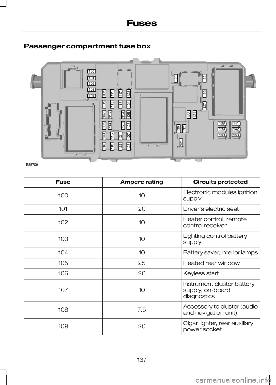
Passenger compartment fuse box
Circuits protected
Ampere rating
Fuse
Electronic modules ignition
supply
10
100
Driver’s electric seat
20
101
Heater control, remote
control receiver
10
102
Lighting control battery
supply
10
103
Battery saver, interior lamps
10
104
Heated rear window
25
105
Keyless start
20
106
Instrument cluster battery
supply, on-board
diagnostics
10
107
Accessory to cluster (audio
and navigation unit)
7.5
108
Cigar lighter, rear auxiliary
power socket
20
109
137
Fuses100101102103104138139140141142143105111117123130132133129134135136137131106112118124109115121127110116122128107113119125108114120126E88709
Page 140 of 226
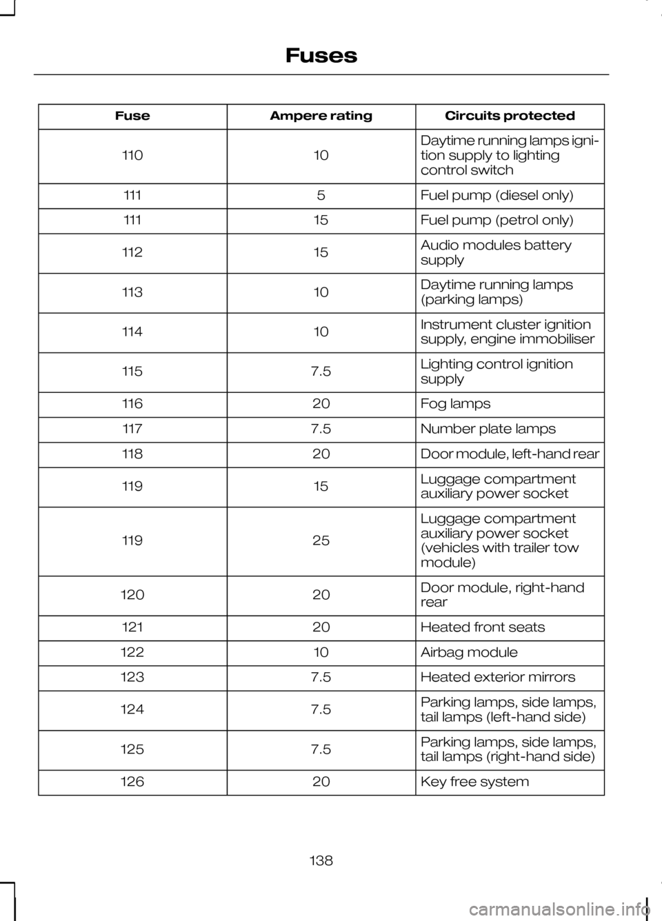
Circuits protected
Ampere rating
Fuse
Daytime running lamps igni-
tion supply to lighting
control switch
10
110
Fuel pump (diesel only)
5
111
Fuel pump (petrol only)
15
111
Audio modules battery
supply
15
112
Daytime running lamps
(parking lamps)
10
113
Instrument cluster ignition
supply, engine immobiliser
10
114
Lighting control ignition
supply
7.5
115
Fog lamps
20
116
Number plate lamps
7.5
117
Door module, left-hand rear
20
118
Luggage compartment
auxiliary power socket
15
119
Luggage compartment
auxiliary power socket
(vehicles with trailer tow
module)
25
119
Door module, right-hand
rear
20
120
Heated front seats
20
121
Airbag module
10
122
Heated exterior mirrors
7.5
123
Parking lamps, side lamps,
tail lamps (left-hand side)
7.5
124
Parking lamps, side lamps,
tail lamps (right-hand side)
7.5
125
Key free system
20
126
138
Fuses
Page 165 of 226
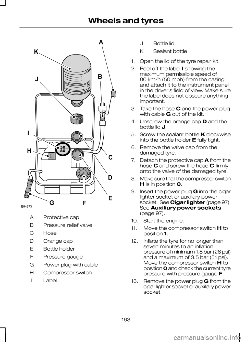
Protective cap
A
Pressure relief valve
B
Hose
C
Orange cap
D
Bottle holder
E
Pressure gauge
F
Power plug with cable
G
Compressor switch
H
Label
I Bottle lid
J
Sealant bottle
K
1. Open the lid of the tyre repair kit.
2. Peel off the label Ishowing the
maximum permissible speed of
80 km/h (50 mph) from the casing
and attach it to the instrument panel
in the driver’s field of view. Make sure
the label does not obscure anything
important.
3. Take the hose Cand the power plug
with cable Gout of the kit.
4. Unscrew the orange cap Dand the
bottle lid J.
5. Screw the sealant bottle Kclockwise
into the bottle holder Efully tight.
6. Remove the valve cap from the damaged tyre.
7. Detach the protective cap Afrom the
hose Cand screw the hose Cfirmly
onto the valve of the damaged tyre.
8. Make sure that the compressor switch
His in position 0.
9. Insert the power plug Ginto the cigar
lighter socket or auxiliary power
socket. See Cigar lighter (page 97).
See Auxiliary power sockets
(page 97).
10. Start the engine.
11. Move the compressor switch Hto
position 1.
12. Inflate the tyre for no longer than seven minutes to an inflation
pressure of minimum 1.8 bar (26 psi)
and a maximum of 3.5 bar (51 psi).
Move the compressor switch Hto
position 0and check the current tyre
pressure with pressure gauge F.
13. Remove the power plug Gfrom the
cigar lighter socket or auxiliary power
socket.
163
Wheels and tyresE94973BJIFECKAGHD