Wheel FORD KUGA 2011 1.G Owners Manual
[x] Cancel search | Manufacturer: FORD, Model Year: 2011, Model line: KUGA, Model: FORD KUGA 2011 1.GPages: 2057
Page 1298 of 2057
Front Drive Halfshafts
Inspection and Verification
NOTE:New front wheel drive halfshafts should not
be installed unless disassembly and inspection
reveals unusual wear.
1. Inspect front wheel driveshaft joint boots for evidence of cracks, tears or splits.
NOTE: While inspecting the front wheel driveshaft
CV joint boots, watch for indentations (dimples) in
the boot convolutions. If an indentation is observed,
it must be removed.
2. Inspect the underbody for any indication of grease splatter in the vicinity of the front wheel
driveshaft CV joint boots outboard and inboard
locations, which is an indication of front wheel
driveshaft CV joint boot and/or front wheel
driveshaft CV joint boot clamp damage. 3. Inspect for inboard CV joint stub shaft pilot
bearing housing seal leakage at the front wheel
driveshaft CV joint.
4. Make sure front axle wheel hub retainer is the correct prevailing torque type.
5. The silicone front wheel driveshaft CV joint boot will sweat during operation, causing a light film
of grease to show on the outside of the front
wheel driveshaft CV joint boot. This condition
is normal.
NOTE: Halfshafts are not balanced and do not
contribute to rotational vibration.
6. If the concerns remain after the inspection, determine the symptoms and go to the Symptom
Chart. For additional Noise, Vibration and
Harshness (NVH). REFER to Section 100-04
[Noise, Vibration and Harshness] .
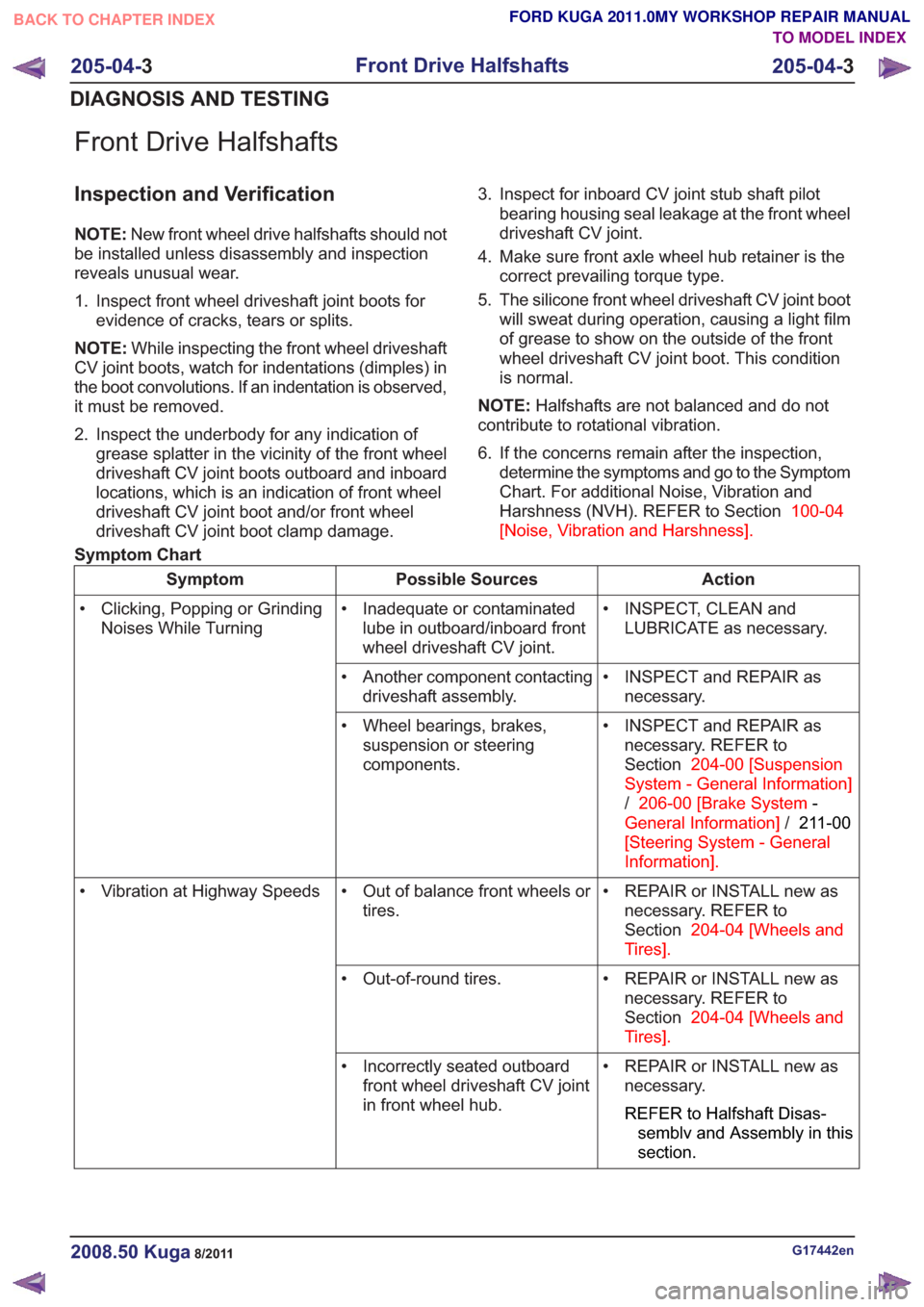
Symptom Chart
Action
Possible Sources
Symptom
• INSPECT, CLEAN andLUBRICATE as necessary.
• Inadequate or contaminated
lube in outboard/inboard front
wheel driveshaft CV joint.
• Clicking, Popping or Grinding
Noises While Turning
• INSPECT and REPAIR asnecessary.
• Another component contacting
driveshaft assembly.
• INSPECT and REPAIR asnecessary. REFER to
Section 204-00 [Suspension
System - General Information]
/ 206-00 [Brake System -
General Information] /211-00
[Steering System - General
Information] .
• Wheel bearings, brakes,
suspension or steering
components.
• REPAIR or INSTALL new asnecessary. REFER to
Section 204-04 [Wheels and
Tires] .
• Out of balance front wheels or
tires.
• Vibration at Highway Speeds
• REPAIR or INSTALL new asnecessary. REFER to
Section 204-04 [Wheels and
Tires] .
• Out-of-round tires.
• REPAIR or INSTALL new asnecessary.
REFER to Halfshaft Disas-
semblv and Assembly in this
section.
• Incorrectly seated outboard
front wheel driveshaft CV joint
in front wheel hub.
G17442en2008.50 Kuga8/2011
205-04- 3
Front Drive Halfshafts
205-04- 3
DIAGNOSIS AND TESTING
TO MODEL INDEX
BACK TO CHAPTER INDEX
FORD KUGA 2011.0MY WORKSHOP REPAIR MANUAL
Page 1299 of 2057
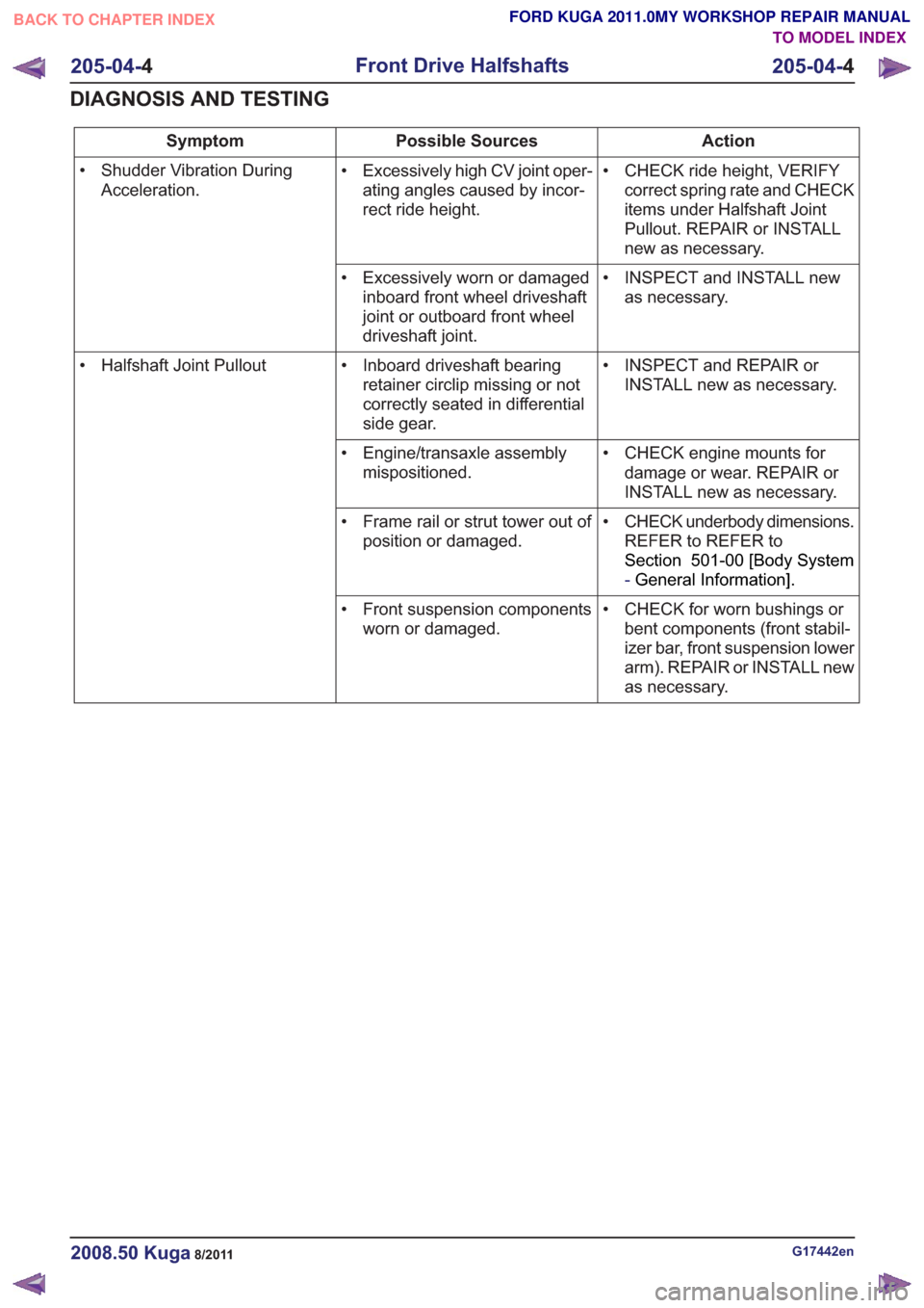
Action
Possible Sources
Symptom
• CHECK ride height, VERIFYcorrect spring rate and CHECK
items under Halfshaft Joint
Pullout. REPAIR or INSTALL
new as necessary.
• Excessively high CV joint oper-
ating angles caused by incor-
rect ride height.
• Shudder Vibration During
Acceleration.
• INSPECT and INSTALL newas necessary.
• Excessively worn or damaged
inboard front wheel driveshaft
joint or outboard front wheel
driveshaft joint.
• INSPECT and REPAIR orINSTALL new as necessary.
• Inboard driveshaft bearing
retainer circlip missing or not
correctly seated in differential
side gear.
• Halfshaft Joint Pullout
• CHECK engine mounts fordamage or wear. REPAIR or
INSTALL new as necessary.
• Engine/transaxle assembly
mispositioned.
• CHECK underbody dimensions.REFER to REFER to
Section 501-00 [Body System
-General Information] .
• Frame rail or strut tower out of
position or damaged.
• CHECK for worn bushings orbent components (front stabil-
izer bar, front suspension lower
arm). REPAIR or INSTALL new
as necessary.
• Front suspension components
worn or damaged.
G17442en2008.50 Kuga8/2011
205-04- 4
Front Drive Halfshafts
205-04- 4
DIAGNOSIS AND TESTING
TO MODEL INDEX
BACK TO CHAPTER INDEX
FORD KUGA 2011.0MY WORKSHOP REPAIR MANUAL
Page 1300 of 2057
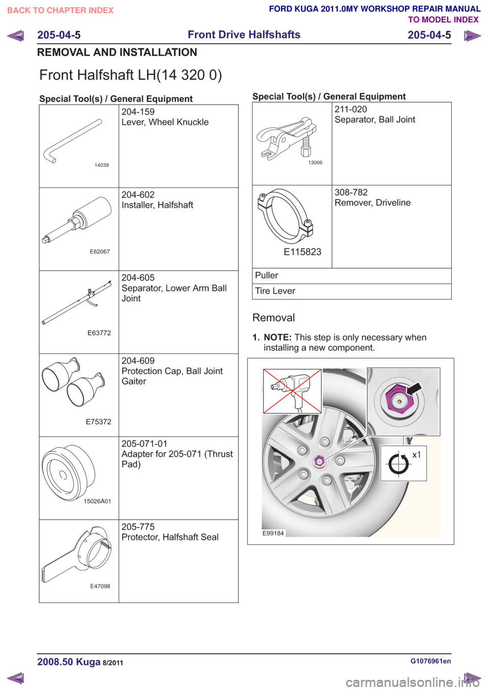
Front Halfshaft LH(14 320 0)
Special Tool(s) / General Equipment204-159
Lever, Wheel Knuckle
14039
204-602
Installer, Halfshaft
E62067
204-605
Separator, Lower Arm Ball
Joint
E63772
204-609
Protection Cap, Ball Joint
Gaiter
E75372
205-071-01
Adapter for 205-071 (Thrust
Pad)
15026A01
205-775
Protector, Halfshaft Seal
E47098
Special Tool(s) / General Equipment211-020
Separator, Ball Joint
13006
308-782
Remover, Driveline
E115823
Puller
Tire Lever
Removal
1. NOTE:This step is only necessary when
installing a new component.
E99184
G1076961en2008.50 Kuga8/2011
205-04- 5
Front Drive Halfshafts
205-04- 5
REMOVAL AND INSTALLATION
TO MODEL INDEX
BACK TO CHAPTER INDEX
FORD KUGA 2011.0MY WORKSHOP REPAIR MANUAL
Page 1301 of 2057
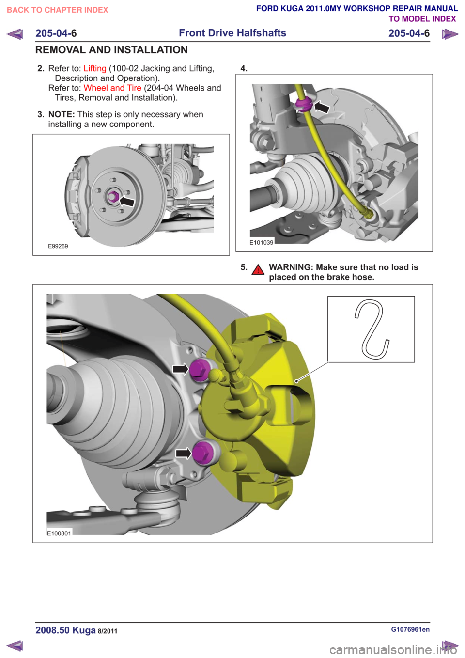
2.Refer to: Lifting(100-02 Jacking and Lifting,
Description and Operation).
Refer to: Wheel and Tire (204-04 Wheels and
Tires, Removal and Installation).
3. NOTE: This step is only necessary when
installing a new component.
E99269
4.
E101039
5. WARNING: Make sure that no load is placed on the brake hose.
E100801
G1076961en2008.50 Kuga8/2011
205-04- 6
Front Drive Halfshafts
205-04- 6
REMOVAL AND INSTALLATION
TO MODEL INDEX
BACK TO CHAPTER INDEX
FORD KUGA 2011.0MY WORKSHOP REPAIR MANUAL
Page 1310 of 2057
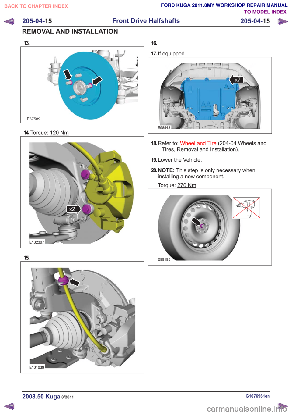
13.
E67589
14.Torque: 120Nm
x2x2
E132307
15.
E101039
16.
17.If equipped.
E98543
x7
18.Refer to: Wheel and Tire (204-04 Wheels and
Tires, Removal and Installation).
19. Lower the Vehicle.
20. N O T E : This step is only necessary when
installing a new component.
Torque: 270
Nm
E99195
G1076961en2008.50 Kuga8/2011
205-04- 15
Front Drive Halfshafts
205-04- 15
REMOVAL AND INSTALLATION
TO MODEL INDEX
BACK TO CHAPTER INDEX
FORD KUGA 2011.0MY WORKSHOP REPAIR MANUAL
Page 1311 of 2057

Front Halfshaft RH — LHD 4WD/RHD 4WD(14 321 0)
Special Tool(s) / General Equipment204-159
Lever, Wheel Knuckle
14039
204-602
Installer, Halfshaft
E62067
204-605
Separator, Lower Arm Ball
Joint
E63772
204-609
Protection Cap, Ball Joint
Gaiter
E75372
205-071-01
Adapter for 205-071 (Thrust
Pad)
15026A01
211-020
Separator, Ball Joint
13006
Puller
Removal
1. NOTE:This step is only necessary when
installing a new component.
E99184
2. Refer to: Lifting(100-02 Jacking and Lifting,
Description and Operation).
Refer to: Wheel and Tire (204-04 Wheels and
Tires, Removal and Installation).
3. NOTE: This step is only necessary when
installing a new component.
E102112
G1076962en2008.50 Kuga8/2011
205-04- 16
Front Drive Halfshafts
205-04- 16
REMOVAL AND INSTALLATION
TO MODEL INDEX
BACK TO CHAPTER INDEX
FORD KUGA 2011.0MY WORKSHOP REPAIR MANUAL
Page 1321 of 2057
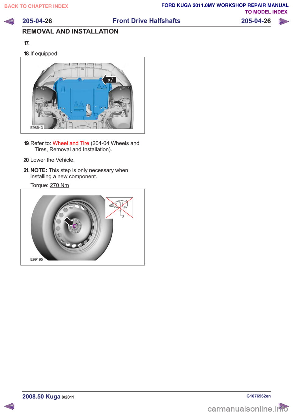
17.
18.If equipped.
E98543
x7
19.Refer to: Wheel and Tire (204-04 Wheels and
Tires, Removal and Installation).
20. Lower the Vehicle.
21. N O T E : This step is only necessary when
installing a new component.
Torque: 270
Nm
E99195
G1076962en2008.50 Kuga8/2011
205-04- 26
Front Drive Halfshafts
205-04- 26
REMOVAL AND INSTALLATION
TO MODEL INDEX
BACK TO CHAPTER INDEX
FORD KUGA 2011.0MY WORKSHOP REPAIR MANUAL
Page 1330 of 2057
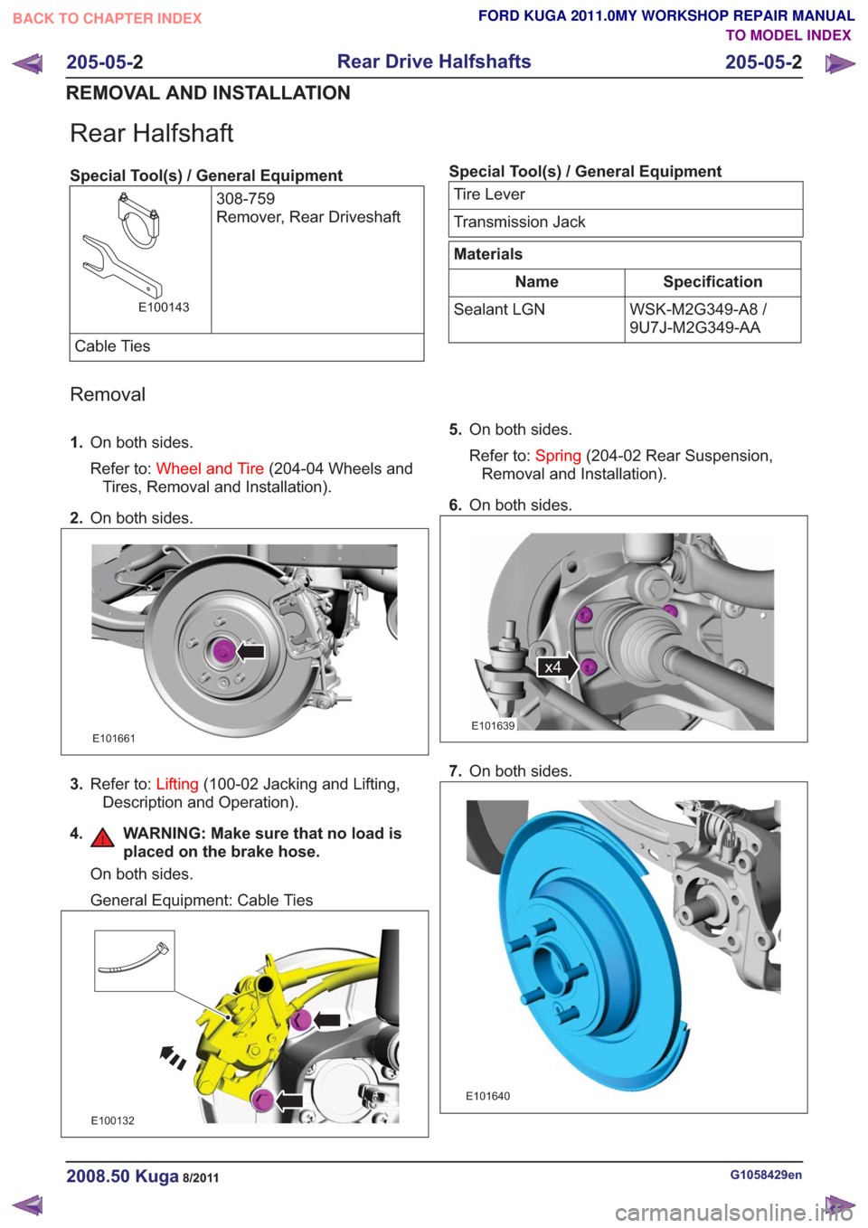
Rear Halfshaft
Special Tool(s) / General Equipment308-759
Remover, Rear Driveshaft
E100143
Cable Ties
Special Tool(s) / General EquipmentTire Lever
Transmission Jack
Materials
Specification
Name
WSK-M2G349-A8 /
9U7J-M2G349-AA
Sealant LGN
Removal
1.
On both sides.
Refer to: Wheel and Tire (204-04 Wheels and
Tires, Removal and Installation).
2. On both sides.
E101661
3.Refer to: Lifting(100-02 Jacking and Lifting,
Description and Operation).
4. WARNING: Make sure that no load is placed on the brake hose.
On both sides.
General Equipment: Cable Ties
E100132
5.On both sides.
Refer to: Spring(204-02 Rear Suspension,
Removal and Installation).
6. On both sides.
x4x4
E101639
7.On both sides.
E101640
G1058429en2008.50 Kuga8/2011
205-05- 2
Rear Drive Halfshafts
205-05- 2
REMOVAL AND INSTALLATION
TO MODEL INDEX
BACK TO CHAPTER INDEX
FORD KUGA 2011.0MY WORKSHOP REPAIR MANUAL
Page 1336 of 2057

15.On both sides.
Refer to: Wheel and Tire (204-04 Wheels and
Tires, Removal and Installation).
16. Refer to: Differential Fluid Level Check (205-02
Rear Drive Axle/Differential, General
Procedures).
G1058429en2008.50 Kuga8/2011
205-05- 8
Rear Drive Halfshafts
205-05- 8
REMOVAL AND INSTALLATION
TO MODEL INDEX
BACK TO CHAPTER INDEX
FORD KUGA 2011.0MY WORKSHOP REPAIR MANUAL
Page 1340 of 2057
Brake System
General EquipmentPressure/vacuum gauge set
The Ford approved diagnostic tool
The brake system operates by transferring effort
applied to the brake pedal by the driver to the
brakes at each wheel.
The braking effort is distributed to each wheel,
using a hydraulic system. The system is assisted
using a vacuum brake booster that reduces pedal
effort and increases hydraulic pressure.
The parking brake operates on the rear wheels
and is applied using a hand operated control.
Inspection and Verification
NOTE: Before carrying out any diagnosis, make
sure that the brake system warning indicator is
functional.
1. Verify the customer concern.
2. Visually inspect for obvious signs of mechanical or electrical damage.
Visual Inspection Chart
Electrical
Mechanical
• Electricalconnector(s)
• Wiring harness(s)
• Switch(es)
• Tire pressure(s)
• Wheels and tires
• Fluid leak(s)
3. If an obvious cause for an observed or reported concern is found, correct the case (if possible)
before proceeding to the next step.
4. If the cause if not visually evident, verify the symptom and refer to the Symptom Chart.
Road Test
Carry out a road test to compare actual vehicle
braking performance with the performance
standards expected by the driver. The ability of the
test driver to make valid comparisons and detect
performance deficiencies will depend on
experience.
The driver should have a thorough knowledge of
the brake system operation and accepted general performance guidelines to make good comparisons
and detect performance concerns.
An experienced technician will always establish a
route that will be used for all brake diagnosis road
tests. The road selected will be reasonably smooth
and level. Gravel or bumpy roads are not suitable
because the surface does not allow the tires to grip
the road equally. Crowned roads should be avoided
because of the large amount of weight shifted to
the low set of wheels on this type of road. Once
the route is established and consistently used, the
road surface variable can be eliminated from the
test results.
Before a road test, get a complete description of
the customer concerns or suspected condition.
From the description, the technician will be able to
match possible causes with symptoms. Certain
components will be identified as possible sources
while others will be eliminated by the evidence.
More importantly, the customer description can
reveal unsafe conditions which should be checked
or corrected before a road test. The description will
also help form the basic approach to the road test
by narrowing the concern to specific components,
vehicle speed or conditions.
Begin the road test with a general brake
performance check. Using the description of the
concern, test the brakes at different vehicle speeds
using both light and heavy pedal pressure.
Determine if the concern is in the front or rear
braking system. First use the foot brake and then
the parking brake. If the condition (i.e. pull,
vibration, pulsation) occurs only on operation of
the parking brake, the concern is in the rear brake
system. If the condition occurs when the foot brake
is depressed, the concern is in the front brake
system.
Avoid locking the brakes and sliding the tires. This
condition will not indicate brake efficiency. A heavily
braked but turning wheel will stop the vehicle in a
shorter distance than locked wheels.
If the concern becomes evident during this check,
make sure it fits the description given before the
road test. If the concern is not evident, attempt to
duplicate the condition using the information from
the description.
If a concern exists, use the Brake System Symptom
Chart in order to isolate it to a specific sub-system
and condition description. From this description, a
list of possible sources can be used to further
G1058975en2008.50 Kuga8/2011
206-00-
4
Brake System - General Information
206-00- 4
DIAGNOSIS AND TESTING
TO MODEL INDEX
BACK TO CHAPTER INDEX
FORD KUGA 2011.0MY WORKSHOP REPAIR MANUAL