fuse box diagram FORD KUGA 2011 1.G Workshop Manual
[x] Cancel search | Manufacturer: FORD, Model Year: 2011, Model line: KUGA, Model: FORD KUGA 2011 1.GPages: 2057
Page 190 of 2057
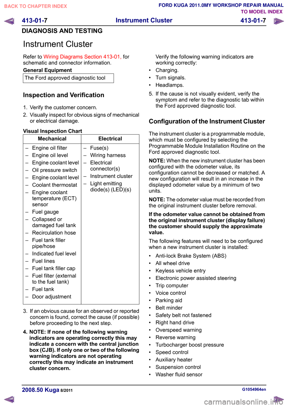
Instrument Cluster
Refer to
Wiring Diagrams Section 413-01, for
schematic and connector information. General Equipment
The Ford approved diagnostic tool
Inspection and Verification
1. Verify the customer concern.
2. Visually inspect for obvious signs of mechanical
or electrical damage.
Visual Inspection Chart Electrical
Mechanical
– Fuse(s)
– Wiring harness
– Electricalconnector(s)
– Instrument cluster
– Light emitting diode(s) (LED)(s)
– Engine oil filter
– Engine oil level
–
Engine coolant level
– Oil pressure switch
– Engine coolant level
– Coolant thermostat
– Engine coolant temperature (ECT)
sensor
– Fuel gauge
– Collapsed or damaged fuel tank
– Recirculation hose
– Fuel tank filler pipe/hose
– Indicated fuel level
– Fuel lines
– Fuel tank filler cap
– Fuel filter (external to the fuel tank)
– Fuel tank
– Door adjustment
3. If an obvious cause for an observed or reported concern is found, correct the cause (if possible)
before proceeding to the next step.
4. NOTE: If none of the following warning indicators are operating correctly this may
indicate a concern with the central junction
box (CJB). If only one or two of the following
warning indicators are not operating
correctly this may indicate an instrument
cluster concern. Verify the following warning indicators are
working correctly:
• Charging.
• Turn signals.
• Headlamps.
5. If the cause is not visually evident, verify the symptom and refer to the diagnostic tab within
the Ford approved diagnostic tool.
Configuration of the Instrument Cluster
The instrument cluster is a programmable module,
which must be configured by selecting the
Programmable Module Installation Routine on the
Ford approved diagnostic tool.
NOTE: When the new instrument cluster has been
configured with the odometer value, its
configuration cannot be decreased or matched. A
new configuration will result in an increase in the
displayed odometer value by a minimum of two
units.
NOTE: The odometer value must be recorded from
the original instrument cluster before removal.
If the odometer value cannot be obtained from
the original instrument cluster (display failure)
the customer should supply the approximate
value.
The following features will need to be configured
when a new instrument cluster is installed:
• Anti-lock Brake System (ABS)
• All wheel drive
• Keyless vehicle entry
• Electronic power assisted steering
• Trip computer
• Voice control
• Parking aid
• Belt minder
• Safety belt not fastened
• Right hand drive
• Overspeed warning
• Reverse warning
• Turbocharger boost pressure
• Speed control
• Auxiliary heater
• Suspension control
• Washer fluid sensor G1054964en
2008.50 Kuga 8/2011 413-01-7
Instrument Cluster
413-01-7
DIAGNOSIS AND TESTINGTO MODEL INDEX
BACK TO CHAPTER INDEX
FORD KUGA 2011.0MY WORKSHOP REPAIR MANUAL
Page 216 of 2057
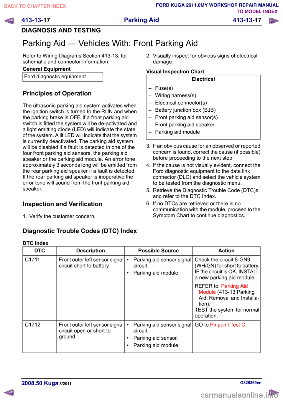
Parking Aid — Vehicles With: Front Parking Aid
Refer to Wiring Diagrams Section 413-13, for
schematic and connector information.
General Equipment
Ford diagnostic equipment
Principles of Operation
The ultrasonic parking aid system activates when
the ignition switch is turned to the RUN and when
the parking brake is OFF. If a front parking aid
switch is fitted the system will be de-activated and
a light emitting diode (LED) will indicate the state
of the system. A lit LED will indicate that the system
is currently deactivated. The parking aid system
will be disabled if a fault is detected in one of the
four front parking aid sensors, the parking aid
speaker or the parking aid module. An error tone
approximately 3 seconds long will be emitted from
the rear parking aid speaker if a fault is detected.
If the rear parking aid speaker is inoperative the
error tone will sound from the front parking aid
speaker.
Inspection and Verification
1. Verify the customer concern. 2. Visually inspect for obvious signs of electrical
damage.
Visual Inspection Chart Electrical
– Fuse(s)
– Wiring harness(s)
– Electrical connector(s)
– Battery junction box (BJB)
– Front parking aid sensor(s)
– Front parking aid speaker
– Parking aid module
3. If an obvious cause for an observed or reported concern is found, correct the cause (if possible)
before proceeding to the next step
4. If the cause is not visually evident, connect the Ford diagnostic equipment to the data link
connector (DLC) and select the vehicle system
to be tested from the diagnostic menu.
5. Retrieve the Diagnostic Trouble Code (DTC)s and refer to the DTC Index.
6. If no DTCs are retrieved or there is no communication with the module, proceed to the
Symptom Chart to continue diagnostics.
Diagnostic Trouble Codes (DTC) Index
DTC Index Action
Possible Source
Description
DTC
Check the circuit 8-GN9
(WH/GN) for short to battery.
IF the circuit is OK, INSTALL
a new parking aid module.
REFER to:Parking Aid
Module (413-13 Parking
Aid, Removal and Installa-
tion).
TEST the system for normal
operation.
• Parking aid sensor signal
circuit.
• Parking aid module.
Front outer left sensor signal
circuit short to battery
C1711
GO toPinpoint Test C.
• Parking aid sensor signal
circuit.
• Parking aid sensor.
• Parking aid module.
Front outer left sensor signal
circuit open or short to
ground
C1712 G325369en
2008.50 Kuga 8/2011 413-13-17
Parking Aid
413-13-17
DIAGNOSIS AND TESTINGTO MODEL INDEX
BACK TO CHAPTER INDEX
FORD KUGA 2011.0MY WORKSHOP REPAIR MANUAL
Page 228 of 2057
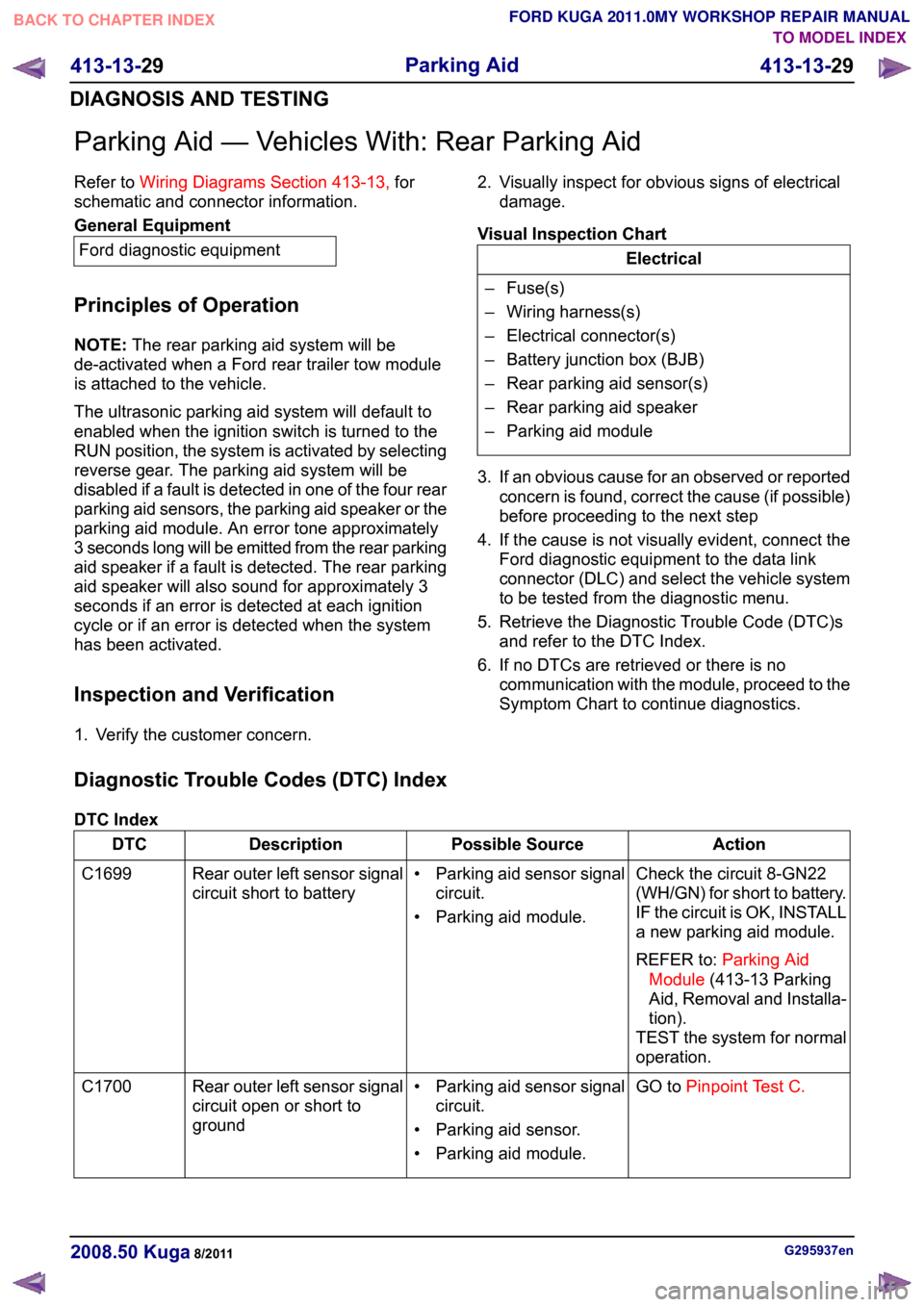
Parking Aid — Vehicles With: Rear Parking Aid
Refer to
Wiring Diagrams Section 413-13, for
schematic and connector information. General Equipment
Ford diagnostic equipment
Principles of Operation
NOTE: The rear parking aid system will be
de-activated when a Ford rear trailer tow module
is attached to the vehicle.
The ultrasonic parking aid system will default to
enabled when the ignition switch is turned to the
RUN position, the system is activated by selecting
reverse gear. The parking aid system will be
disabled if a fault is detected in one of the four rear
parking aid sensors, the parking aid speaker or the
parking aid module. An error tone approximately
3 seconds long will be emitted from the rear parking
aid speaker if a fault is detected. The rear parking
aid speaker will also sound for approximately 3
seconds if an error is detected at each ignition
cycle or if an error is detected when the system
has been activated.
Inspection and Verification
1. Verify the customer concern. 2. Visually inspect for obvious signs of electrical
damage.
Visual Inspection Chart Electrical
– Fuse(s)
– Wiring harness(s)
– Electrical connector(s)
– Battery junction box (BJB)
– Rear parking aid sensor(s)
– Rear parking aid speaker
– Parking aid module
3. If an obvious cause for an observed or reported concern is found, correct the cause (if possible)
before proceeding to the next step
4. If the cause is not visually evident, connect the Ford diagnostic equipment to the data link
connector (DLC) and select the vehicle system
to be tested from the diagnostic menu.
5. Retrieve the Diagnostic Trouble Code (DTC)s and refer to the DTC Index.
6. If no DTCs are retrieved or there is no communication with the module, proceed to the
Symptom Chart to continue diagnostics.
Diagnostic Trouble Codes (DTC) Index
DTC Index Action
Possible Source
Description
DTC
Check the circuit 8-GN22
(WH/GN) for short to battery.
IF the circuit is OK, INSTALL
a new parking aid module.
REFER to:Parking Aid
Module (413-13 Parking
Aid, Removal and Installa-
tion).
TEST the system for normal
operation.
• Parking aid sensor signal
circuit.
• Parking aid module.
Rear outer left sensor signal
circuit short to battery
C1699
GO toPinpoint Test C.
• Parking aid sensor signal
circuit.
• Parking aid sensor.
• Parking aid module.
Rear outer left sensor signal
circuit open or short to
ground
C1700 G295937en
2008.50 Kuga 8/2011 413-13-29
Parking Aid
413-13-29
DIAGNOSIS AND TESTINGTO MODEL INDEX
BACK TO CHAPTER INDEX
FORD KUGA 2011.0MY WORKSHOP REPAIR MANUAL
Page 263 of 2057
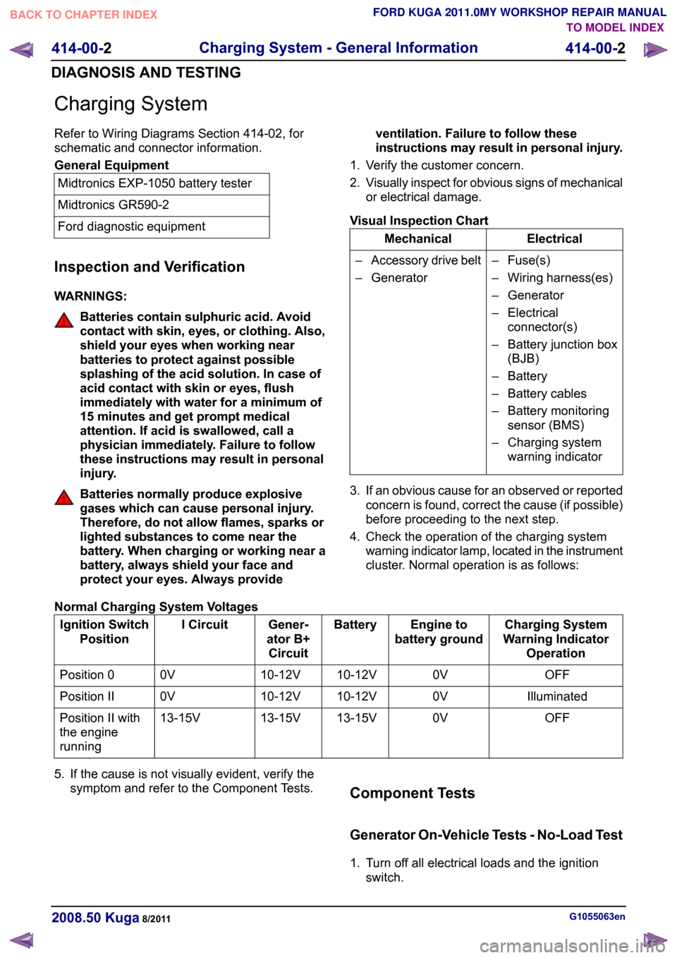
Charging System
Refer to Wiring Diagrams Section 414-02, for
schematic and connector information.
General Equipment
Midtronics EXP-1050 battery tester
Midtronics GR590-2
Ford diagnostic equipment
Inspection and Verification
WARNINGS: Batteries contain sulphuric acid. Avoid
contact with skin, eyes, or clothing. Also,
shield your eyes when working near
batteries to protect against possible
splashing of the acid solution. In case of
acid contact with skin or eyes, flush
immediately with water for a minimum of
15 minutes and get prompt medical
attention. If acid is swallowed, call a
physician immediately. Failure to follow
these instructions may result in personal
injury.
Batteries normally produce explosive
gases which can cause personal injury.
Therefore, do not allow flames, sparks or
lighted substances to come near the
battery. When charging or working near a
battery, always shield your face and
protect your eyes. Always provide
ventilation. Failure to follow these
instructions may result in personal injury.
1. Verify the customer concern.
2. Visually inspect for obvious signs of mechanical
or electrical damage.
Visual Inspection Chart Electrical
Mechanical
– Fuse(s)
– Wiring harness(es)
– Generator
– Electricalconnector(s)
– Battery junction box (BJB)
– Battery
– Battery cables
– Battery monitoring sensor (BMS)
– Charging system warning indicator
–
Accessory drive belt
– Generator
3. If an obvious cause for an observed or reported concern is found, correct the cause (if possible)
before proceeding to the next step.
4. Check the operation of the charging system warning indicator lamp, located in the instrument
cluster. Normal operation is as follows:
Normal Charging System Voltages Charging System
Warning Indicator Operation
Engine to
battery ground
Battery
Gener-
ator B+ Circuit
I Circuit
Ignition Switch
Position
OFF
0V
10-12V
10-12V
0V
Position 0
Illuminated
0V
10-12V
10-12V
0V
Position II
OFF
0V
13-15V
13-15V
13-15V
Position II with
the engine
running
5. If the cause is not visually evident, verify the symptom and refer to the Component Tests. Component Tests
Generator On-Vehicle Tests - No-Load Test
1. Turn off all electrical loads and the ignition
switch. G1055063en
2008.50 Kuga 8/2011 414-00-2
Charging System - General Information
414-00-2
DIAGNOSIS AND TESTINGTO MODEL INDEX
BACK TO CHAPTER INDEX
FORD KUGA 2011.0MY WORKSHOP REPAIR MANUAL
Page 288 of 2057
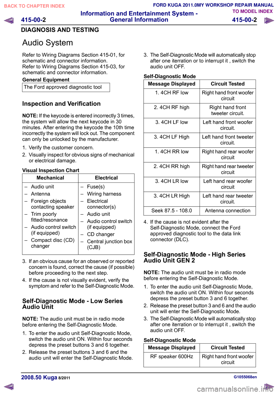
Audio System
Refer to Wiring Diagrams Section 415-01, for
schematic and connector information.
Refer to Wiring Diagrams Section 415-03, for
schematic and connector information.
General Equipment
The Ford approved diagnostic tool
Inspection and Verification
NOTE: If the keycode is entered incorrectly 3 times,
the system will allow the next keycode in 30
minutes. After entering the keycode the 10th time
incorrectly the system will lock out. The component
can only be unlocked by the manufacturer.
1. Verify the customer concern.
2. Visually inspect for obvious signs of mechanical
or electrical damage.
Visual Inspection Chart Electrical
Mechanical
– Fuse(s)
– Wiring harness
– Electricalconnector(s)
– Audio unit
– Audio control switch (if equipped)
– CD changer
– Central junction box (CJB)
– Audio unit
– Antenna
– Foreign objects
contacting speaker
– Trim poorly fitted/resonance
– Audio control switch (if equipped)
– Compact disc (CD) changer
3. If an obvious cause for an observed or reported concern is found, correct the cause (if possible)
before proceeding to the next step.
4. If the cause is not visually evident, verify the symptom and refer to the Self-Diagnostic Mode.
Self-Diagnostic Mode - Low Series
Audio Unit
NOTE: The audio unit must be in radio mode
before entering the Self-Diagnostic Mode.
1. To enter the audio unit Self-Diagnostic Mode, switch the audio unit ON. Within four seconds
depress the preset buttons 3 and 6 together.
2. Release the preset buttons 3 and 6 and the audio unit will enter the Self-Diagnostic Mode. 3.
The Self-Diagnostic Mode will automatically stop
after one iterration or to interrupt it , switch the
audio unit OFF.
Self-Diagnostic Mode Circuit Tested
Message Displayed
Right hand front woofercircuit
1. 4CH RF low
Right hand fronttweeter circuit.
2. 4CH RF high
Left hand front woofercircuit.
3. 4CH LF low
Left hand front tweetercircuit.
3. 4CH LF High
Right hand rear woofercircuit
1. 4CH RR low
Right hand rear tweetercircuit
2. 4CH RR high
Left hand rear woofercircuit
3. 4CH LR low
Left hand rear tweetercircuit.
3. 4CH LR High
Antenna connection
Seek 87.5 - 108.0
4. If the cause is not evident after the Self-Diagnostic Mode, connect the Ford
approved diagnostic tool to the data link
connector (DLC).
Self-Diagnostic Mode - High Series
Audio Unit GEN 2
NOTE: The audio unit must be in radio mode
before entering the Self-Diagnostic Mode.
1. To enter the audio unit Self-Diagnostic Mode, switch the audio unit ON. Within four seconds
depress the preset button 3 and 6 together.
2. Release the preset button 3 and 6 and the audio
unit will enter the Self-Diagnostic Mode.
3. The Self-Diagnostic Mode will automatically stop
after one iterration or to interrupt it , switch the
audio unit OFF.
Self-Diagnostic Mode Circuit Tested
Message Displayed
Right hand front woofercircuit
RF speaker 600Hz G1055068en
2008.50 Kuga 8/2011 415-00-2
Information and Entertainment System -
General Information
415-00-2
DIAGNOSIS AND TESTINGTO MODEL INDEX
BACK TO CHAPTER INDEX
FORD KUGA 2011.0MY WORKSHOP REPAIR MANUAL
Page 374 of 2057
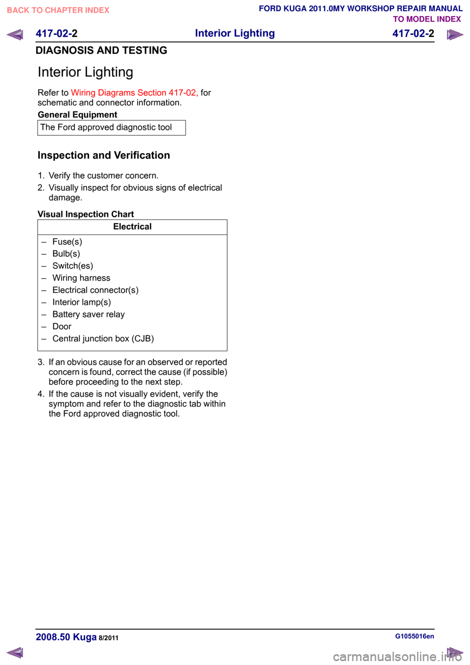
Interior Lighting
Refer to
Wiring Diagrams Section 417-02, for
schematic and connector information. General Equipment
The Ford approved diagnostic tool
Inspection and Verification
1. Verify the customer concern.
2. Visually inspect for obvious signs of electrical damage.
Visual Inspection Chart Electrical
– Fuse(s)
– Bulb(s)
– Switch(es)
– Wiring harness
– Electrical connector(s)
– Interior lamp(s)
– Battery saver relay
– Door
– Central junction box (CJB)
3. If an obvious cause for an observed or reported concern is found, correct the cause (if possible)
before proceeding to the next step.
4. If the cause is not visually evident, verify the symptom and refer to the diagnostic tab within
the Ford approved diagnostic tool. G1055016en
2008.50 Kuga 8/2011 417-02-2
Interior Lighting
417-02-2
DIAGNOSIS AND TESTINGTO MODEL INDEX
BACK TO CHAPTER INDEX
FORD KUGA 2011.0MY WORKSHOP REPAIR MANUAL
Page 452 of 2057
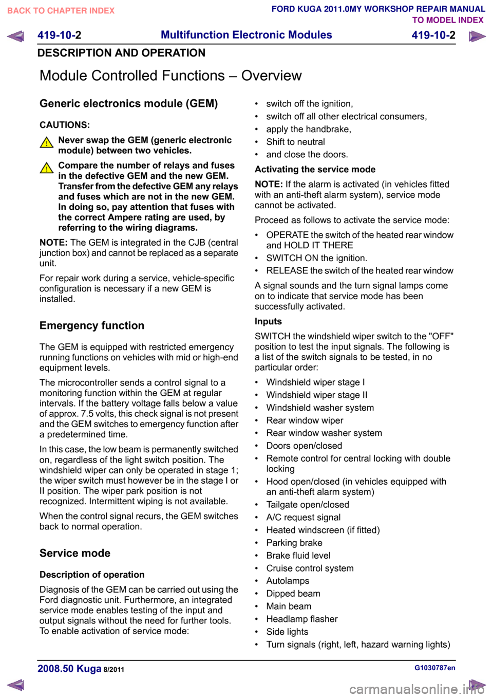
Module Controlled Functions – Overview
Generic electronics module (GEM)
CAUTIONS:
Never swap the GEM (generic electronic
module) between two vehicles.
Compare the number of relays and fuses
in the defective GEM and the new GEM.
Transfer from the defective GEM any relays
and fuses which are not in the new GEM.
In doing so, pay attention that fuses with
the correct Ampere rating are used, by
referring to the wiring diagrams.
NOTE: The GEM is integrated in the CJB (central
junction box) and cannot be replaced as a separate
unit.
For repair work during a service, vehicle-specific
configuration is necessary if a new GEM is
installed.
Emergency function
The GEM is equipped with restricted emergency
running functions on vehicles with mid or high-end
equipment levels.
The microcontroller sends a control signal to a
monitoring function within the GEM at regular
intervals. If the battery voltage falls below a value
of approx. 7.5 volts, this check signal is not present
and the GEM switches to emergency function after
a predetermined time.
In this case, the low beam is permanently switched
on, regardless of the light switch position. The
windshield wiper can only be operated in stage 1;
the wiper switch must however be in the stage I or
II position. The wiper park position is not
recognized. Intermittent wiping is not available.
When the control signal recurs, the GEM switches
back to normal operation.
Service mode
Description of operation
Diagnosis of the GEM can be carried out using the
Ford diagnostic unit. Furthermore, an integrated
service mode enables testing of the input and
output signals without the need for further tools.
To enable activation of service mode: • switch off the ignition,
• switch off all other electrical consumers,
• apply the handbrake,
• Shift to neutral
• and close the doors.
Activating the service mode
NOTE:
If the alarm is activated (in vehicles fitted
with an anti-theft alarm system), service mode
cannot be activated.
Proceed as follows to activate the service mode:
• OPERATE the switch of the heated rear window
and HOLD IT THERE
• SWITCH ON the ignition.
• RELEASE the switch of the heated rear window
A signal sounds and the turn signal lamps come
on to indicate that service mode has been
successfully activated.
Inputs
SWITCH the windshield wiper switch to the "OFF"
position to test the input signals. The following is
a list of the switch signals to be tested, in no
particular order:
• Windshield wiper stage I
• Windshield wiper stage II
• Windshield washer system
• Rear window wiper
• Rear window washer system
• Doors open/closed
• Remote control for central locking with double locking
• Hood open/closed (in vehicles equipped with an anti-theft alarm system)
• Tailgate open/closed
• A/C request signal
• Heated windscreen (if fitted)
• Parking brake
• Brake fluid level
• Cruise control system
• Autolamps
• Dipped beam
• Main beam
• Headlamp flasher
• Side lights
• Turn signals (right, left, hazard warning lights) G1030787en
2008.50 Kuga 8/2011 419-10-2
Multifunction Electronic Modules
419-10-2
DESCRIPTION AND OPERATIONTO MODEL INDEX
BACK TO CHAPTER INDEX
FORD KUGA 2011.0MY WORKSHOP REPAIR MANUAL
Page 464 of 2057
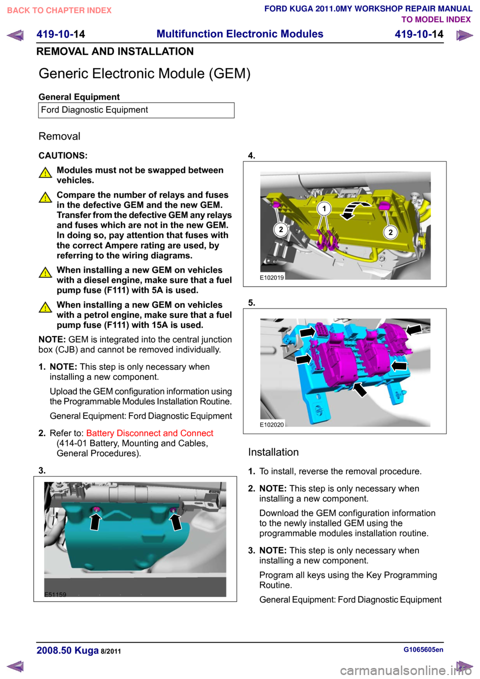
Generic Electronic Module (GEM)
General Equipment
Ford Diagnostic Equipment
Removal
CAUTIONS: Modules must not be swapped between
vehicles.
Compare the number of relays and fuses
in the defective GEM and the new GEM.
Transfer from the defective GEM any relays
and fuses which are not in the new GEM.
In doing so, pay attention that fuses with
the correct Ampere rating are used, by
referring to the wiring diagrams.
When installing a new GEM on vehicles
with a diesel engine, make sure that a fuel
pump fuse (F111) with 5A is used.
When installing a new GEM on vehicles
with a petrol engine, make sure that a fuel
pump fuse (F111) with 15A is used.
NOTE: GEM is integrated into the central junction
box (CJB) and cannot be removed individually.
1. NOTE: This step is only necessary when
installing a new component.
Upload the GEM configuration information using
the Programmable Modules Installation Routine.
General Equipment: Ford Diagnostic Equipment
2. Refer to: Battery Disconnect and Connect
(414-01 Battery, Mounting and Cables,
General Procedures).
3. 4.
5.
Installation
1.
To install, reverse the removal procedure.
2. NOTE: This step is only necessary when
installing a new component.
Download the GEM configuration information
to the newly installed GEM using the
programmable modules installation routine.
3. NOTE: This step is only necessary when
installing a new component.
Program all keys using the Key Programming
Routine.
General Equipment: Ford Diagnostic Equipment G1065605en
2008.50 Kuga 8/2011 419-10-14
Multifunction Electronic Modules
419-10-14
REMOVAL AND INSTALLATIONTO MODEL INDEX
BACK TO CHAPTER INDEX
FORD KUGA 2011.0MY WORKSHOP REPAIR MANUALE51159 122E102019 E102020
Page 1753 of 2057
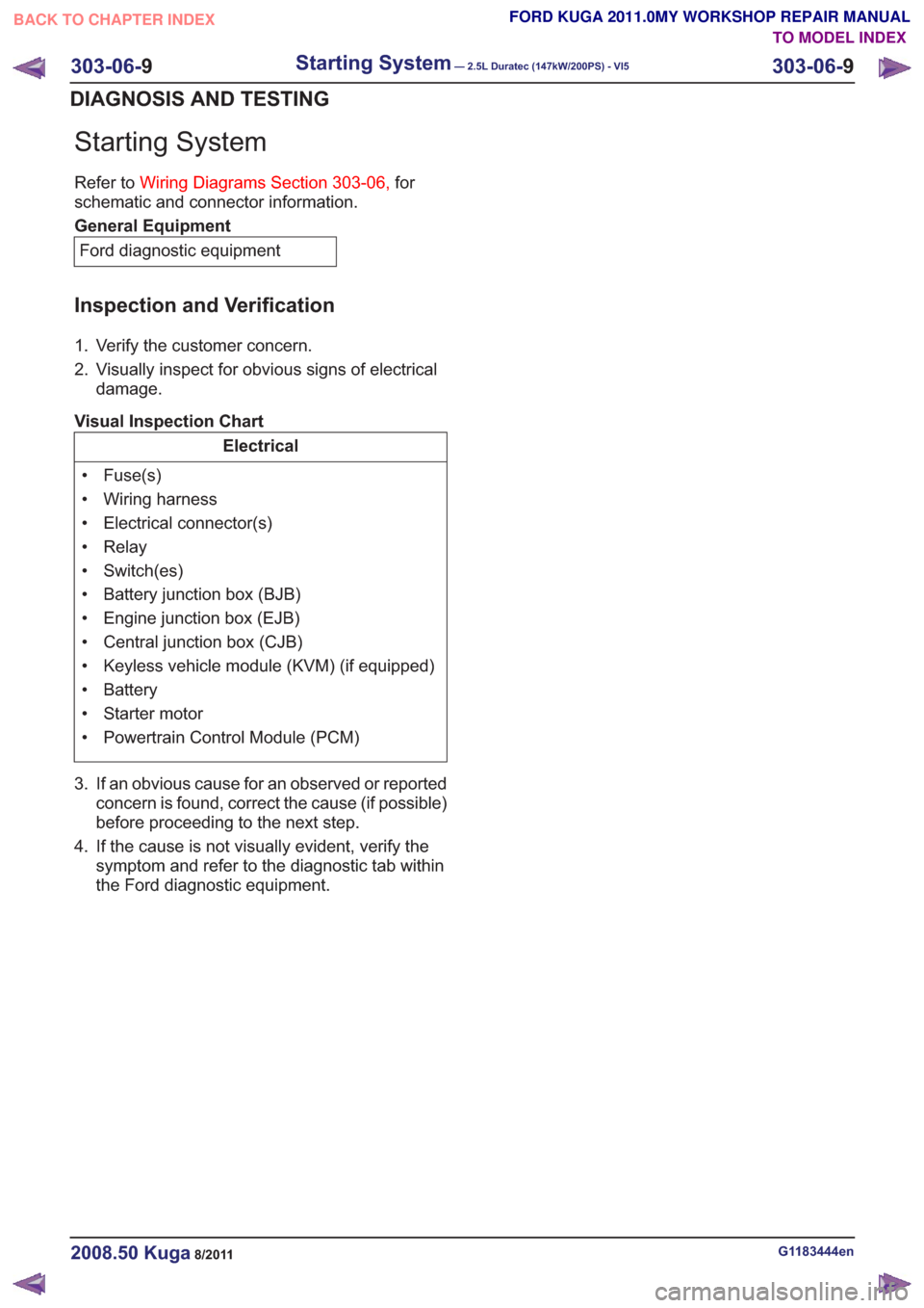
Starting System
Refer toWiring Diagrams Section 303-06, for
schematic and connector information.
General Equipment
Ford diagnostic equipment
Inspection and Verification
1. Verify the customer concern.
2. Visually inspect for obvious signs of electrical damage.
Visual Inspection Chart
Electrical
• Fuse(s)
• Wiring harness
• Electrical connector(s)
• Relay
• Switch(es)
• Battery junction box (BJB)
• Engine junction box (EJB)
• Central junction box (CJB)
• Keyless vehicle module (KVM) (if equipped)
• Battery
• Starter motor
• Powertrain Control Module (PCM)
3. If an obvious cause for an observed or reported concern is found, correct the cause (if possible)
before proceeding to the next step.
4. If the cause is not visually evident, verify the symptom and refer to the diagnostictab within
the Ford diagnostic equipment .
G1183444en2008.50 Kuga8/2011
303-06-9
Starting System— 2.5L Duratec (147kW/200PS) - VI5303-06-
9
DIAGNOSIS AND TESTING
TO MODEL INDEX
BACK TO CHAPTER INDEX
FORD KUGA 2011.0MY WORKSHOP REPAIR MANUAL