connector FORD KUGA 2011 1.G Owners Manual
[x] Cancel search | Manufacturer: FORD, Model Year: 2011, Model line: KUGA, Model: FORD KUGA 2011 1.GPages: 2057
Page 1971 of 2057
Spring Lock Couplings
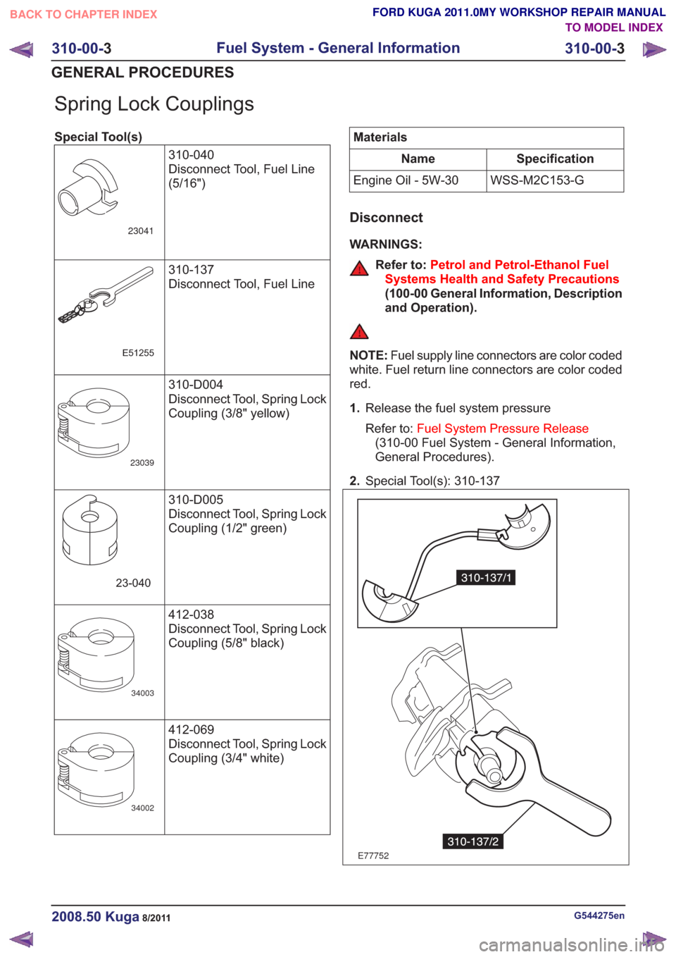
Special Tool(s)310-040
Disconnect Tool, Fuel Line
(5/16")
23041
310-137
Disconnect Tool, Fuel Line
E51255
310-D004
Disconnect Tool, Spring Lock
Coupling (3/8" yellow)
23039
310-D005
Disconnect Tool, Spring Lock
Coupling (1/2" green)
23-040
412-038
Disconnect Tool, Spring Lock
Coupling (5/8" black)
34003
412-069
Disconnect Tool, Spring Lock
Coupling (3/4" white)
34002
Materials
Specification
Name
WSS-M2C153-G
Engine Oil - 5W-30
Disconnect
WARNINGS:
Refer to: Petrol and Petrol-Ethanol Fuel
Systems Health and Safety Precautions
(100-00 General Information, Description
and Operation).
NOTE: Fuel supply line connectors are color coded
white. Fuel return line connectors are color coded
red.
1. Release the fuel system pressure
Refer to: Fuel System Pressure Release
(310-00 Fuel System - General Information,
General Procedures).
2. Special Tool(s): 310-137
E77752
G544275en2008.50 Kuga8/2011
310-00- 3
Fuel System - General Information
310-00- 3
GENERAL PROCEDURES
TO MODEL INDEX
BACK TO CHAPTER INDEX
FORD KUGA 2011.0MY WORKSHOP REPAIR MANUAL
Page 1974 of 2057
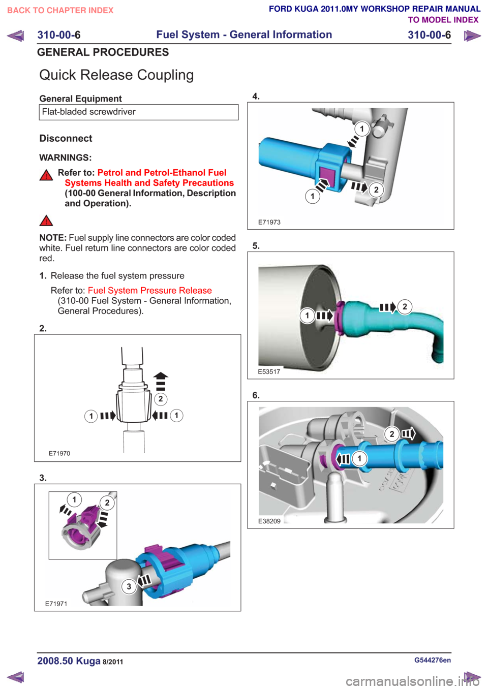
Quick Release Coupling
General EquipmentFlat-bladed screwdriver
Disconnect
WARNINGS:
Refer to: Petrol and Petrol-Ethanol Fuel
Systems Health and Safety Precautions
(100-00 General Information, Description
and Operation).
NOTE: Fuel supply line connectors are color coded
white. Fuel return line connectors are color coded
red.
1. Release the fuel system pressure
Refer to: Fuel System Pressure Release
(310-00 Fuel System - General Information,
General Procedures).
2.
E71970
1 2
1
3.
E71971
3
12
4.
E71973
21
1
5.
E53517
1
2
6.
E38209
2
1
G544276en2008.50 Kuga8/2011
310-00- 6
Fuel System - General Information
310-00- 6
GENERAL PROCEDURES
TO MODEL INDEX
BACK TO CHAPTER INDEX
FORD KUGA 2011.0MY WORKSHOP REPAIR MANUAL
Page 1986 of 2057
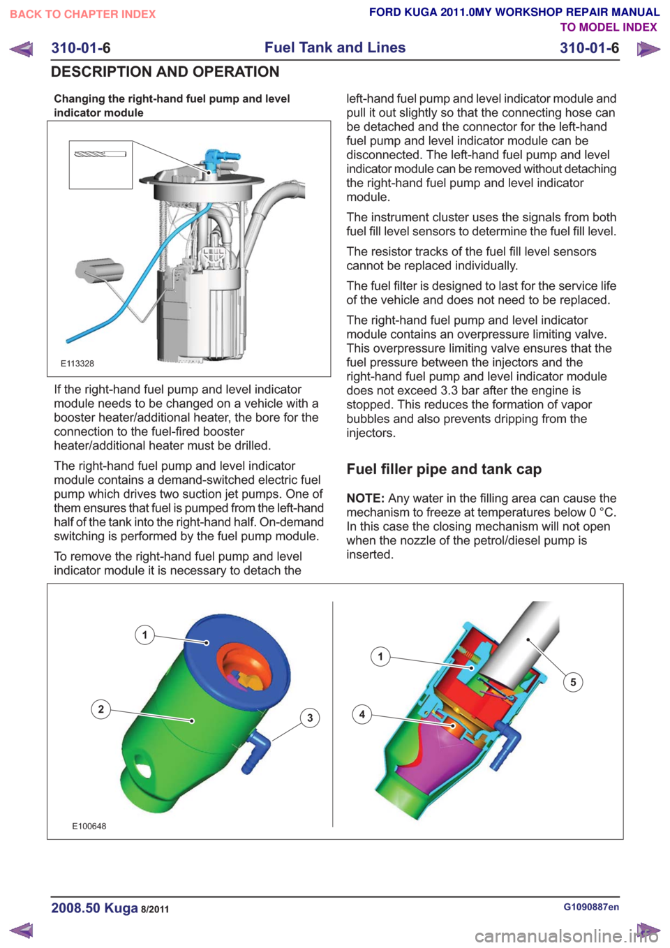
Changing the right-hand fuel pump and level
indicator module
E113328
If the right-hand fuel pump and level indicator
module needs to be changed on a vehicle with a
booster heater/additional heater, the bore for the
connection to the fuel-fired booster
heater/additional heater must be drilled.
The right-hand fuel pump and level indicator
module contains a demand-switched electric fuel
pump which drives two suction jet pumps. One of
them ensures that fuel is pumped from the left-hand
half of the tank into the right-hand half. On-demand
switching is performed by the fuel pump module.
To remove the right-hand fuel pump and level
indicator module it is necessary to detach theleft-hand fuel pump and level indicator module and
pull it out slightly so that the connecting hose can
be detached and the connector for the left-hand
fuel pump and level indicator module can be
disconnected. The left-hand fuel pump and level
indicator module can be removed without detaching
the right-hand fuel pump and level indicator
module.
The instrument cluster uses the signals from both
fuel fill level sensors to determine the fuel fill level.
The resistor tracks of the fuel fill level sensors
cannot be replaced individually.
The fuel filter is designed to last for the service life
of the vehicle and does not need to be replaced.
The right-hand fuel pump and level indicator
module contains an overpressure limiting valve.
This overpressure limiting valve ensures that the
fuel pressure between the injectors and the
right-hand fuel pump and level indicator module
does not exceed 3.3 bar after the engine is
stopped. This reduces the formation of vapor
bubbles and also prevents dripping from the
injectors.
Fuel filler pipe and tank cap
NOTE:
Any water in the filling area can cause the
mechanism to freeze at temperatures below 0 °C.
In this case the closing mechanism will not open
when the nozzle of the petrol/diesel pump is
inserted.
43
1
2
1
5
43
1
2
1
5
E100648
G1090887en2008.50 Kuga8/2011
310-01- 6
Fuel Tank and Lines
310-01- 6
DESCRIPTION AND OPERATION
TO MODEL INDEX
BACK TO CHAPTER INDEX
FORD KUGA 2011.0MY WORKSHOP REPAIR MANUAL
Page 2002 of 2057
Acceleration Control
Inspection and Verification
1. Verify the customer concern.
2. Visually inspect for obvious signs of mechanicalor electrical damage.
Visual Inspection Chart
Electrical
Mechanical
– Wiring harness(s)
– Wiring harnessretaining clips
– Electrical connector(s)
– Accelerator pedal
– Powertrain control module (PCM)
– Electronic throttle body
– Accelerator pedal
– Throttle body
3. If an obvious cause for an observed or reported concern is found, correct the cause (if possible)
before proceeding to the next step.
4. If the cause is not visually evident, verify the symptom and refer to the diagnostic tab within
the Ford approved diagnostic tool.
G1080719en2008.50 Kuga8/2011
310-02- 2
Acceleration Control
310-02- 2
DIAGNOSIS AND TESTING
TO MODEL INDEX
BACK TO CHAPTER INDEX
FORD KUGA 2011.0MY WORKSHOP REPAIR MANUAL
Page 2009 of 2057
• Parking brake switch.– The parking brake switch is hard-wired to theGEM. The parking brake switch sends a
signal to the GEM when the parking brake is
operated. The GEM activates the parking
brake indicator lamp in the instrument cluster.
If the parking brake indicator lamp is lit,
cruise control cannot be activated.
• Back-up light switch – The backup lamp switch is hard-wired to the GEM. The backup lamp switch sends a signal
to the GEM when reverse gear is engaged.
The GEM activates the reversing lamp.
Cruise control cannot be activated when
reverse gear is engaged.
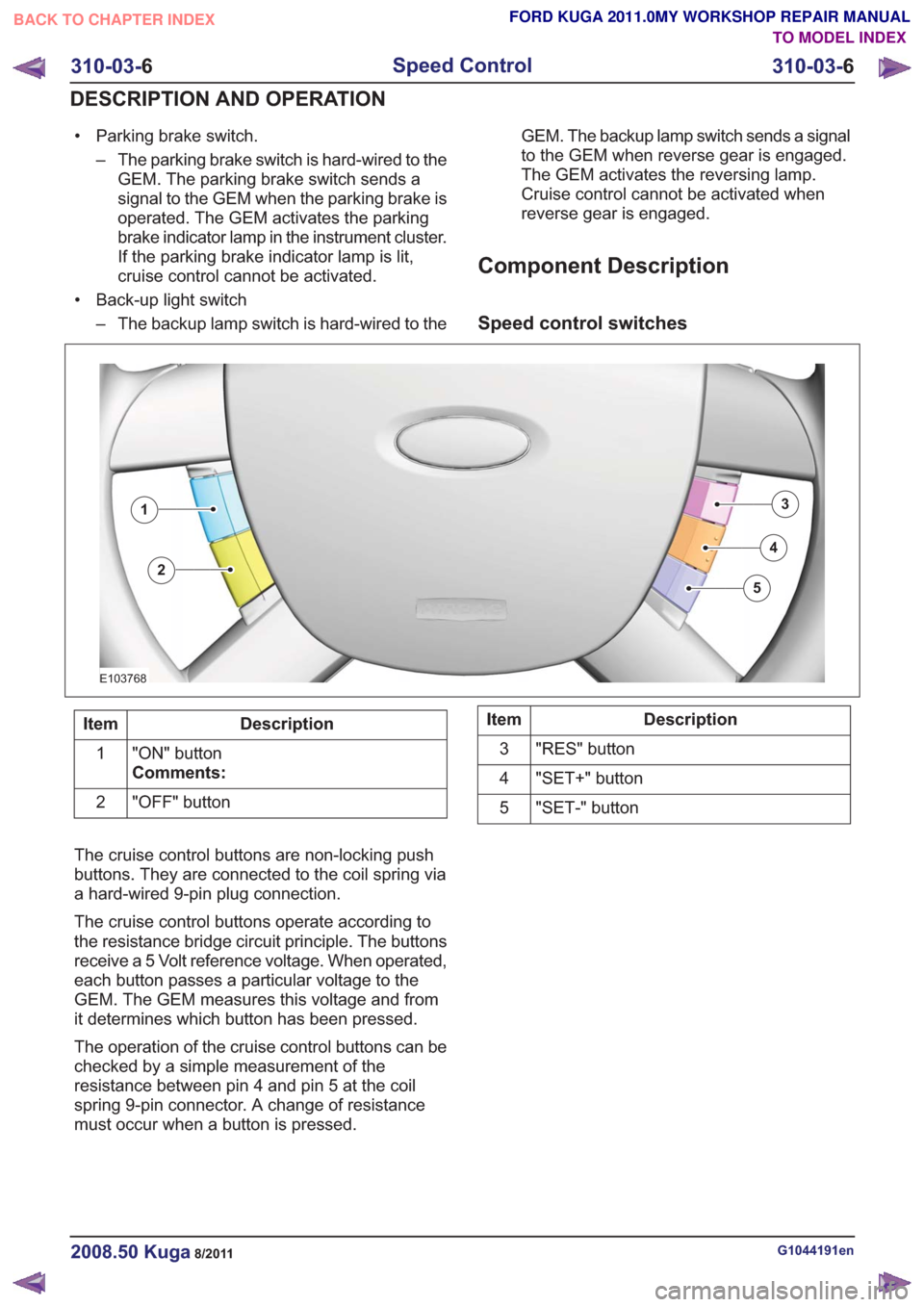
Component Description
Speed control switches
E103768
3
4
5
1
2
Description
Item
"ON" button
Comments:
1
"OFF" button
2Description
Item
"RES" button
3
"SET+" button
4
"SET-" button
5
The cruise control buttons are non-locking push
buttons. They are connected to the coil spring via
a hard-wired 9-pin plug connection.
The cruise control buttons operate according to
the resistance bridge circuit principle. The buttons
receive a 5 Volt reference voltage. When operated,
each button passes a particular voltage to the
GEM. The GEM measures this voltage and from
it determines which button has been pressed.
The operation of the cruise control buttons can be
checked by a simple measurement of the
resistance between pin 4 and pin 5 at the coil
spring 9-pin connector. A change of resistance
must occur when a button is pressed.
G1044191en2008.50 Kuga8/2011
310-03- 6
Speed Control
310-03- 6
DESCRIPTION AND OPERATION
TO MODEL INDEX
BACK TO CHAPTER INDEX
FORD KUGA 2011.0MY WORKSHOP REPAIR MANUAL
Page 2010 of 2057
Speed Control
Inspection and Verification
1. Verify the customer concern by operating thesystem.
2. Visually inspect for obvious signs of mechanical or electrical damage.
Visual Inspection Chart
Electrical
Mechanical
– Fuse(s)
– Connections
– Wiring harness
– Clockspring
– Loose or corrodedelectrical
connector(s)
– Speed control switch
– Brake pedal position (BPP) deactivation
switch
– Clutch pedal posi- tion (CPP) deactiva-
tion Switch
– Powertrain control module (PCM)
– Central junction box (CJB)
– Brake pedal
– Clutch pedal
3. NOTE: Not all passenger junction box (PJB) variants support the speed control system.
NOTE: If the PJB is configured for speed control
disable, speed control operation is not transmitted,
no Diagnostic Trouble Codes (DTCs) are
generated.
If an obvious cause for an observed or reported
concern is found, correct the cause (if possible)
before proceeding to the next step.
4. If the cause is not visually evident, verify the symptom and refer to the diagnostic tab within
the Ford approved diagnostic tool.
G1054908en2008.50 Kuga8/2011
310-03- 7
Speed Control
310-03- 7
DIAGNOSIS AND TESTING
TO MODEL INDEX
BACK TO CHAPTER INDEX
FORD KUGA 2011.0MY WORKSHOP REPAIR MANUAL
Page 2014 of 2057
Climate Control System
Refer to Wiring Diagrams Section 412-00, for
schematic and connector information.
Special Tool(s) / General EquipmentTerminal Probe Kit
418-S035
29011A
Digital Multimeter (compatible with K-type
thermocouple)
The Ford approved diagnostic tool
Refrigerant center
Thermometer - Fluke 80 PK-8 (FSE number 260
4102 001 07)
Inspection and Checking
NOTE:The electronic automatic temperature
control (EATC) module is integrated into the air
conditioning control assembly.
1. VERIFY customer concern.
2. Visually CHECK for any obvious mechanical or electrical damage.
NOTE: Ensure correct locking of the wiring harness
connector.
Visual Inspection
Electrical
Mechanical
• Fuses
• Wiring harness
• Connector
• Refrigerant lines
• Condenser core
• Coolant level
• Drive belt
• A/C compressor
3. RECTIFY any obvious causes for a concern found during the visual inspection before
performing any further tests. CHECK the
operation of the system.
4. If the concern is still present after the visual inspection, perform fault diagnosis on the
electronic engine management, the charging
system, the generic electronic module (GEM)
and the instrument cluster (vehicles with EATC:
read out the EATC fault memory as well) using the Ford approved diagnostic tool and RECTIFY
the fault(s) displayed in accordance with the
fault description. CHECK the operation of the
system.
5. For vehicles with no stored fault(s), PROCEED in accordance with the Symptom Chart
according to the fault symptom.
6. Following checking or elimination of the fault(s) and after completion of operations, the fault
memories of all vehicle modules must be READ
OUT and any stored faults must be DELETED.
Refrigerant Circuit - Quick Check
WARNING: The air conditioning system is
filled with refrigerant R134a. Observe
"Health and Safety Precautions". For
further information
REFER to: Air Conditioning (A/C) System
Recovery, Evacuation and Charging
(412-00 Climate Control System - General
Information, General Procedures).
Refrigerant circuit check
WARNING: Under certain circumstances,
refrigerant lines and A/C components may
be extremely hot or cold. Exercising care,
touch the refrigerant lines or A/C
components in order to check this. Failure
to follow these instructions may result in
personal injury.
When the A/C system is operating, the following
conditions should apply:
• The refrigerant line from the refrigerant compressor to the condenser must be hot.
• The refrigerant line from the A/C condenser to the fixed orifice tube must be warm, but not so
hot as the refrigerant line mentioned above.
• Determine the difference in temperature upstream and downstream of the A/C condenser
by measuring the temperatures at the refrigerant
lines. The temperature difference should be
more than 20° C, depending on the ambient
temperature. If the temperature difference is
less, check the condenser for contamination or
damage to the fins as well as operation of the
radiator fans.
G1055878en2008.50 Kuga8/2011
412-00- 3
Climate Control System - General Information
412-00- 3
DIAGNOSIS AND TESTING
TO MODEL INDEX
BACK TO CHAPTER INDEX
FORD KUGA 2011.0MY WORKSHOP REPAIR MANUAL