start FORD KUGA 2011 1.G Owners Manual
[x] Cancel search | Manufacturer: FORD, Model Year: 2011, Model line: KUGA, Model: FORD KUGA 2011 1.GPages: 2057
Page 1879 of 2057
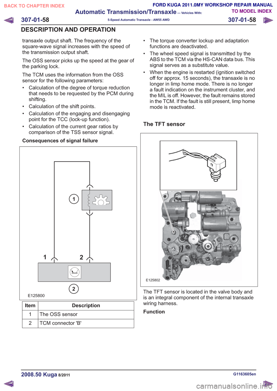
transaxle output shaft. The frequency of the
square-wave signal increases with the speed of
the transmission output shaft.
The OSS sensor picks up the speed at the gear of
the parking lock.
The TCM uses the information from the OSS
sensor for the following parameters:
• Calculation of the degree of torque reductionthat needs to be requested by the PCM during
shifting.
• Calculation of the shift points.
• Calculation of the engaging and disengaging point for the TCC (lock-up function).
• Calculation of the current gear ratios by comparison of the TSS sensor signal.
Consequences of signal failure
E125800
1 2
2
1
Description
Item
The OSS sensor
1
TCM connector 'B'
2 • The torque converter lockup and adaptation
functions are deactivated.
• The wheel speed signal is transmitted by the ABS to the TCM via the HS-CAN data bus. This
signal serves as a substitute value.
• When the engine is restarted (ignition switched off for approx. 15 seconds), the transaxle is no
longer in limp home mode. There is no longer
a fault indication on the instrument cluster, and
the MIL is off. However, the fault remains stored
in the TCM. If the fault is still present, limp home
mode is reactivated.
The TFT sensor
E125802
The TFT sensor is located in the valve body and
is an integral component of the internal transaxle
wiring harness.
Function
G1163605en2008.50 Kuga8/2011
307-01- 58
Automatic Transmission/Transaxle
— Vehicles With:
5-Speed Automatic Transaxle - AW55 AWD
307-01- 58
DESCRIPTION AND OPERATION
TO MODEL INDEX
BACK TO CHAPTER INDEX
FORD KUGA 2011.0MY WORKSHOP REPAIR MANUAL
Page 1880 of 2057
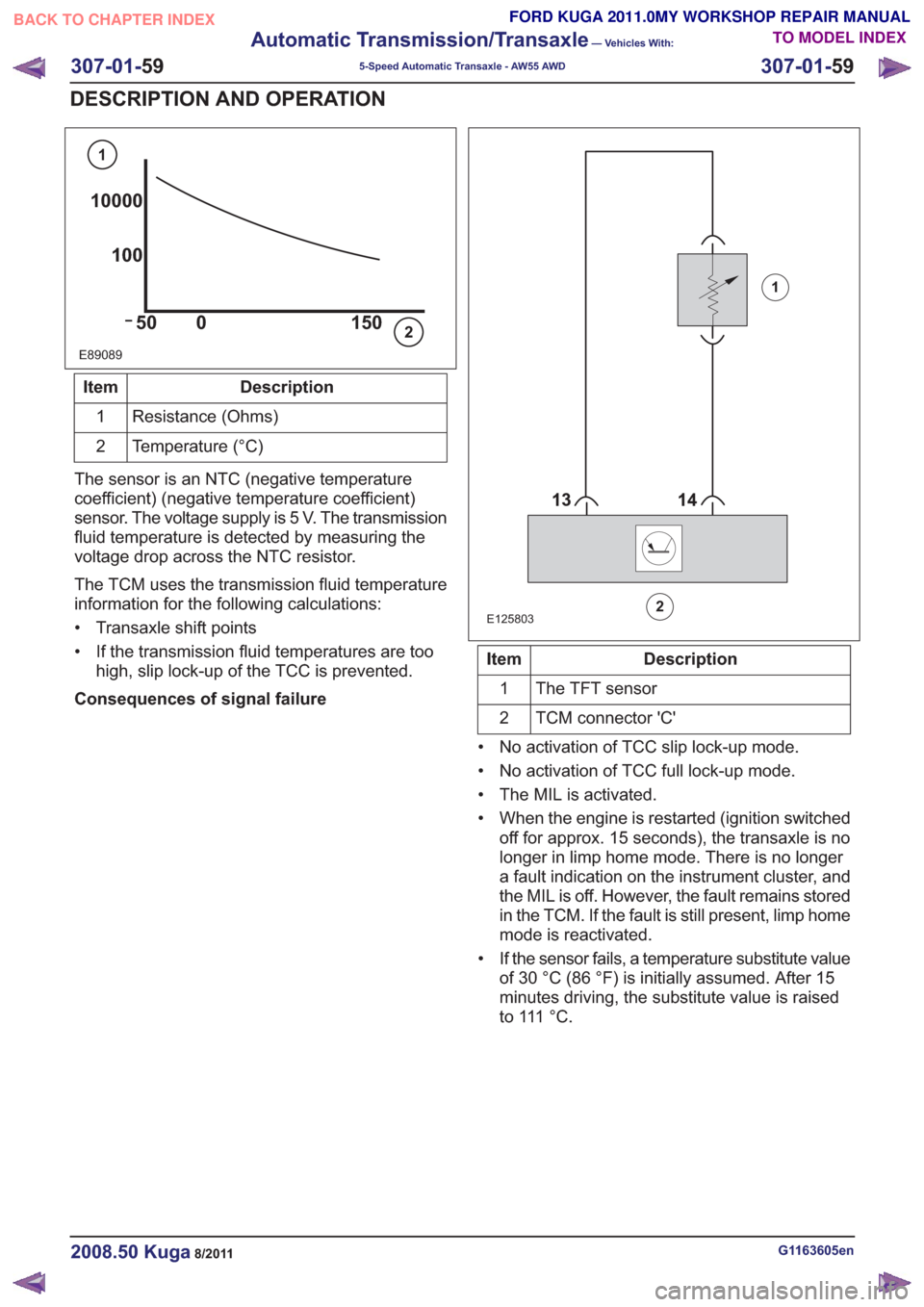
E89089
10000100
50 0 150
1
2
Description
Item
Resistance (Ohms)
1
Temperature (°C)
2
The sensor is an NTC (negative temperature
coefficient) (negative temperature coefficient)
sensor. The voltage supply is 5 V. The transmission
fluid temperature is detected by measuring the
voltage drop across the NTC resistor.
The TCM uses the transmission fluid temperature
information for the following calculations:
• Transaxle shift points
• If the transmission fluid temperatures are too high, slip lock-up of the TCC is prevented.
Consequences of signal failure
88
E125803
1
2
Description
Item
The TFT sensor
1
TCM connector 'C'
2
• No activation of TCC slip lock-up mode.
• No activation of TCC full lock-up mode.
• The MIL is activated.
• When the engine is restarted (ignition switched off for approx. 15 seconds), the transaxle is no
longer in limp home mode. There is no longer
a fault indication on the instrument cluster, and
the MIL is off. However, the fault remains stored
in the TCM. If the fault is still present, limp home
mode is reactivated.
• If the sensor fails, a temperature substitute value of 30 °C (86 °F) is initially assumed. After 15
minutes driving, the substitute value is raised
t o 111 ° C .
G1163605en2008.50 Kuga8/2011
307-01- 59
Automatic Transmission/Transaxle
— Vehicles With:
5-Speed Automatic Transaxle - AW55 AWD
307-01- 59
DESCRIPTION AND OPERATION
TO MODEL INDEX
BACK TO CHAPTER INDEX
FORD KUGA 2011.0MY WORKSHOP REPAIR MANUAL
Page 1881 of 2057
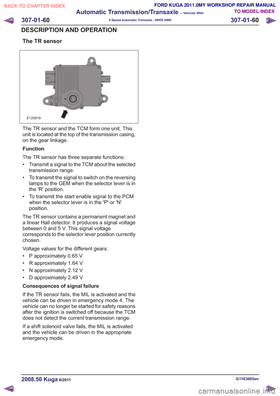
The TR sensor
E125819
The TR sensor and the TCM form one unit. This
unit is located at the top of the transmission casing,
on the gear linkage.
Function
The TR sensor has three separate functions:
• Transmit a signal to the TCM about the selectedtransmission range.
• To transmit the signal to switch on the reversing lamps to the GEM when the selector lever is in
the 'R' position.
• To transmit the start enable signal to the PCM when the selector lever is in the 'P' or 'N'
position.
The TR sensor contains a permanent magnet and
a linear Hall detector. It produces a signal voltage
between 0 and 5 V. This signal voltage
corresponds to the selector lever position currently
chosen.
Voltage values for the different gears:
• P approximately 0.65 V
• R approximately 1.64 V
• N approximately 2.12 V
• D approximately 2.49 V
Consequences of signal failure
If the TR sensor fails, the MIL is activated and the
vehicle can be driven in emergency mode 4. The
vehicle can no longer be started for safety reasons
after the ignition is switched off because the TCM
does not detect the current transmission range.
If a shift solenoid valve fails, the MIL is activated
and the vehicle can be driven in the appropriate
emergency mode.
G1163605en2008.50 Kuga8/2011
307-01- 60
Automatic Transmission/Transaxle
— Vehicles With:
5-Speed Automatic Transaxle - AW55 AWD
307-01- 60
DESCRIPTION AND OPERATION
TO MODEL INDEX
BACK TO CHAPTER INDEX
FORD KUGA 2011.0MY WORKSHOP REPAIR MANUAL
Page 1882 of 2057
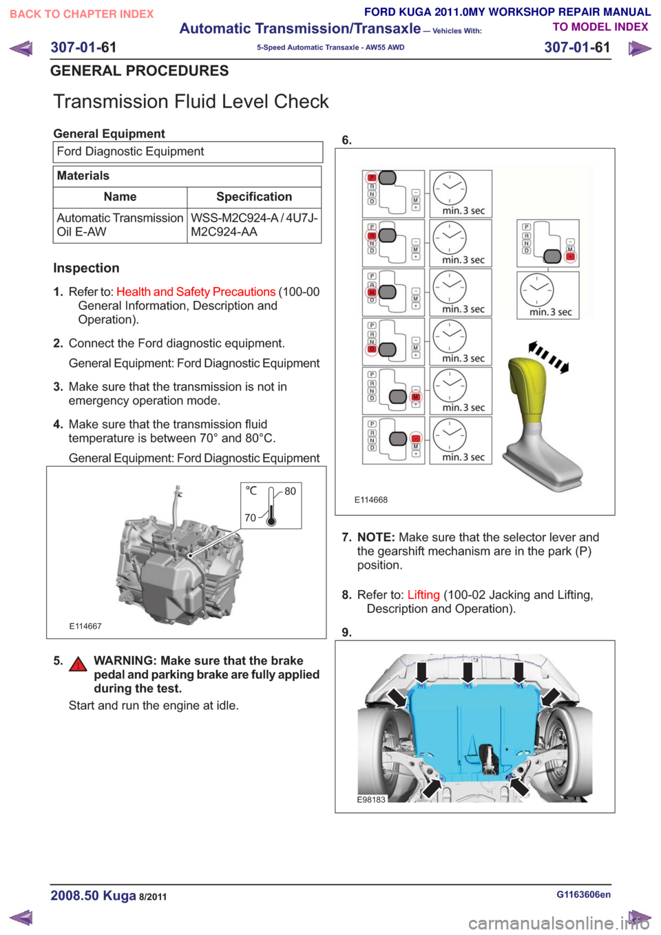
Transmission Fluid Level Check
General EquipmentFord Diagnostic Equipment
Materials
Specification
Name
WSS-M2C924-A / 4U7J-
M2C924-AA
Automatic Transmission
Oil E-AW
Inspection
1.
Refer to: Health and Safety Precautions (100-00
General Information, Description and
Operation).
2. Connect the Ford diagnostic equipment.
General Equipment: Ford Diagnostic Equipment
3. Make sure that the transmission is not in
emergency operation mode.
4. Make sure that the transmission fluid
temperature is between 70° and 80°C.
General Equipment: Ford Diagnostic Equipment
80
70
E114667
5. WARNING: Make sure that the brake pedal and parking brake are fully applied
during the test.
Start and run the engine at idle. 6.
E114668
7. NOTE:
Make sure that the selector lever and
the gearshift mechanism are in the park (P)
position.
8. Refer to: Lifting(100-02 Jacking and Lifting,
Description and Operation).
9.
E98183
G1163606en2008.50 Kuga8/2011
307-01- 61
Automatic Transmission/Transaxle
— Vehicles With:
5-Speed Automatic Transaxle - AW55 AWD
307-01- 61
GENERAL PROCEDURES
TO MODEL INDEX
BACK TO CHAPTER INDEX
FORD KUGA 2011.0MY WORKSHOP REPAIR MANUAL
Page 1885 of 2057
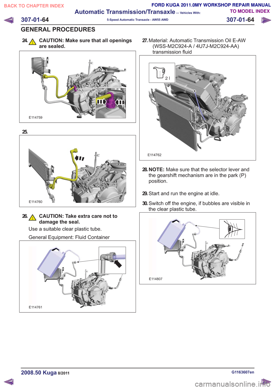
24. CAUTION: Make sure that all openingsare sealed.
E114759
25.
E114760
26. CAUTION: Take extra care not todamage the seal.
Use a suitable clear plastic tube.
General Equipment: Fluid Container
E114761
27.Material: Automatic Transmission Oil E-AW
(WSS-M2C924-A / 4U7J-M2C924-AA)
transmission fluid
E114762
2l
28. N O T E : Make sure that the selector lever and
the gearshift mechanism are in the park (P)
position.
29. Start and run the engine at idle.
30. Switch off the engine, if bubbles are visible in
the clear plastic tube.
E114807
G1163607en2008.50 Kuga8/2011
307-01- 64
Automatic Transmission/Transaxle
— Vehicles With:
5-Speed Automatic Transaxle - AW55 AWD
307-01- 64
GENERAL PROCEDURES
TO MODEL INDEX
BACK TO CHAPTER INDEX
FORD KUGA 2011.0MY WORKSHOP REPAIR MANUAL
Page 1886 of 2057
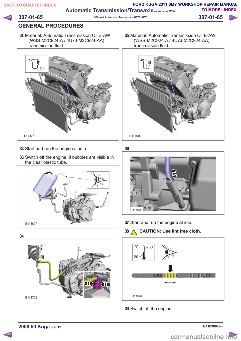
31.Material: Automatic Transmission Oil E-AW
(WSS-M2C924-A / 4U7J-M2C924-AA)
transmission fluid
E114762
2l
32. Start and run the engine at idle.
33. Switch off the engine, if bubbles are visible in
the clear plastic tube.
E114807
34.
E114759
35.Material: Automatic Transmission Oil E-AW
(WSS-M2C924-A / 4U7J-M2C924-AA)
transmission fluid
E114992
36.
E114993
37. Start and run the engine at idle.
38. CAUTION: Use lint free cloth.
E114934
30
20
39. Switch off the engine.
G1163607en2008.50 Kuga8/2011
307-01- 65
Automatic Transmission/Transaxle
— Vehicles With:
5-Speed Automatic Transaxle - AW55 AWD
307-01- 65
GENERAL PROCEDURES
TO MODEL INDEX
BACK TO CHAPTER INDEX
FORD KUGA 2011.0MY WORKSHOP REPAIR MANUAL
Page 1934 of 2057
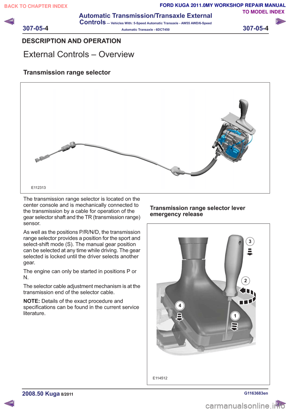
External Controls – Overview
Transmission range selector
E112313
The transmission range selector is located on the
center console and is mechanically connected to
the transmission by a cable for operation of the
gear selector shaft and the TR (transmission range)
sensor.
As well as the positions P/R/N/D, the transmission
range selector provides a position for the sport and
select-shift mode (S). The manual gear position
can be selected at any time while driving. The gear
selected is locked until the driver selects another
gear.
The engine can only be started in positions P or
N.
The selector cable adjustment mechanism is at the
transmission end of the selector cable.
NOTE:Details of the exact procedure and
specifications can be found in the current service
literature.
Transmission range selector lever
emergency release
E114512
1
2
3
4
G1163683en2008.50 Kuga8/2011
DESCRIPTION AND OPERATION
TO MODEL INDEX
BACK TO CHAPTER INDEX
FORD KUGA 2011.0MY WORKSHOP REPAIR MANUAL
307-05-
4
Automatic Transmission/Transaxle External
Controls
— Vehicles With: 5-Speed Automatic Transaxle - AW55 AWD/6-Speed
Automatic Transaxle - 6DCT450
307-05-4
.
Page 1936 of 2057
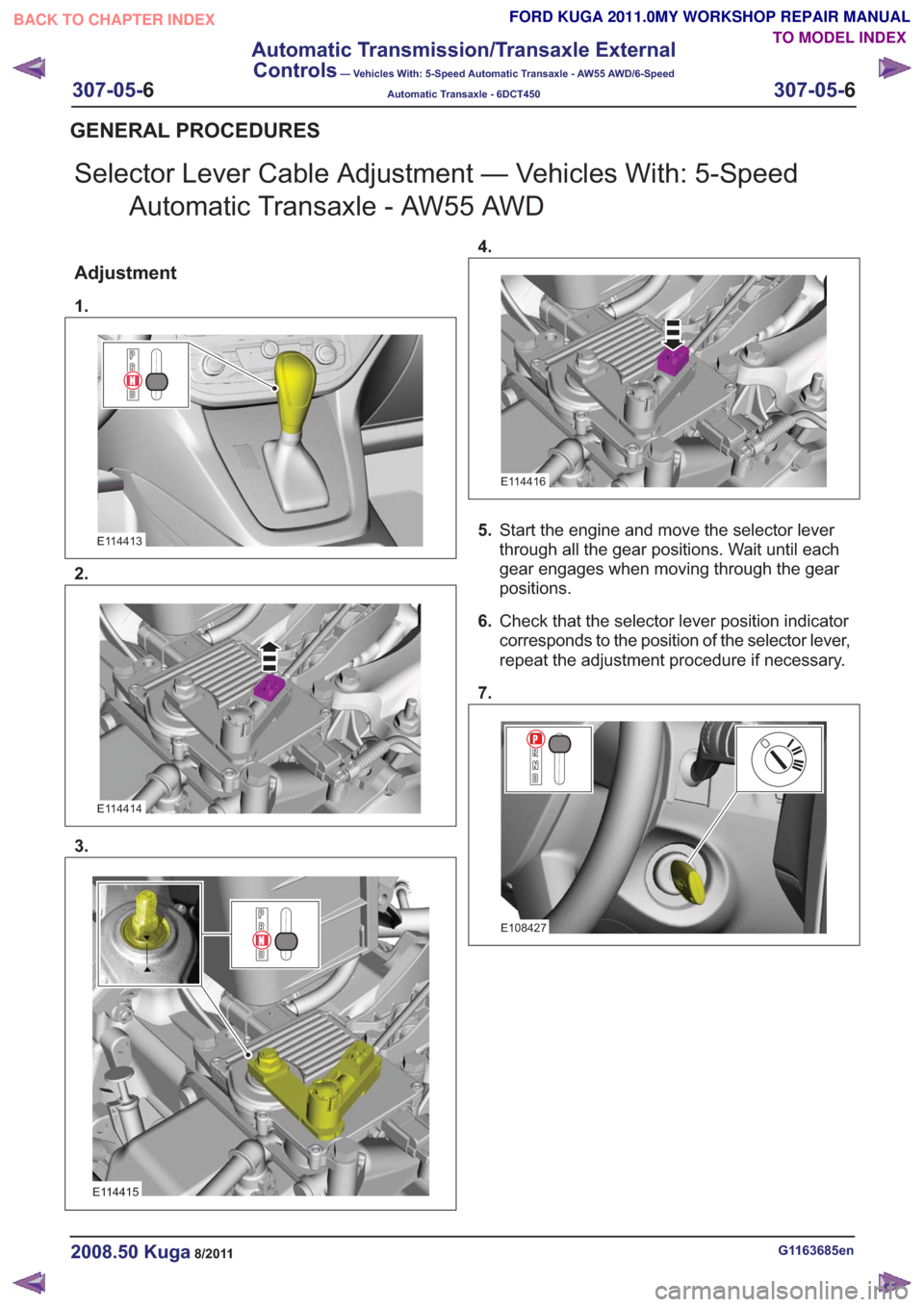
Selector Lever Cable Adjustment — Vehicles With: 5-SpeedAutomatic Transaxle - AW55 AWD
Adjustment
1.
E114413
2.
E114414
3.
E114415
4.
E114416
5.Start the engine and move the selector lever
through all the gear positions. Wait until each
gear engages when moving through the gear
positions.
6. Check that the selector lever position indicator
corresponds to the position of the selector lever,
repeat the adjustment procedure if necessary.
7.
E108427
G1163685en2008.50 Kuga8/2011
GENERAL PROCEDURES
TO MODEL INDEX
BACK TO CHAPTER INDEX
FORD KUGA 2011.0MY WORKSHOP REPAIR MANUAL
307-05-
6
Automatic Transmission/Transaxle External
Controls
— Vehicles With: 5-Speed Automatic Transaxle - AW55 AWD/6-Speed
Automatic Transaxle - 6DCT450
307-05-6
.
Page 1950 of 2057
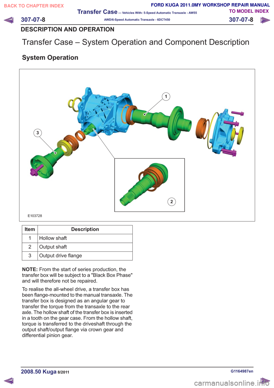
Transfer Case – System Operation and Component Description
System Operation
1
2
3
E103728
Description
Item
Hollow shaft
1
Output shaft
2
Output drive flange
3
NOTE: From the start of series production, the
transfer box will be subject to a "Black Box Phase"
and will therefore not be repaired.
To realise the all-wheel drive, a transfer box has
been flange-mounted to the manual transaxle. The
transfer box is designed as an angular gear to
transfer the torque from the transaxle to the rear
axle. The hollow shaft of the transfer box is inserted
in a tooth on the gear case. From the hollow shaft,
torque is transferred to the driveshaft through the
output shaft/output flange via crown gear and
differential pinion gear.
G1164987en2008.50 Kuga8/2011
307-07- 8
Transfer Case
— Vehicles With: 5-Speed Automatic Transaxle - AW55
AWD/6-Speed Automatic Transaxle - 6DCT450
307-07- 8
DESCRIPTION AND OPERATION
TO MODEL INDEX
BACK TO CHAPTER INDEX
FORD KUGA 2011.0MY WORKSHOP REPAIR MANUAL
Page 1970 of 2057
Fuel System — Vehicles With: Fuel Additive Tank
General EquipmentFord diagnostic equipment
Principles of Operation
WARNINGS:
This procedure involves fuel additive
handling. Be prepared for fuel additive
spillage at all times and always observe
fuel handling precautions. Failure to follow
these instructions may result in personal
injury.
Eye, hand, ear protection and protective
clothing are required to be worn during
any general service or removal and
installation service procedure of fuel
additive system components. Failure to
follow this instruction may result in
personal injury.
In case of fuel additive fluid contact with
the skin or the eyes, flush immediately with
water for a minimum of 15 minutes and
seek prompt medical attention. Failure to
follow these instructions may result in
personal injury.
If fuel additive fluid is swallowed, call a
physician immediately. Rinse mouth
immediately with water, do not induce
vomiting. Failure to follow these
instructions may result in personal injury.
Always provide adequate ventilation when
working on the fuel additive fluid system
or related components. Failure to follow
these instructions may result in personal
injury.
Do not smoke or carry lighted tobacco or
open flame of any type when working on
or near any fuel related components.
Highly flammable vapors are always
present and may ignite. Failure to follow
these instructions may result in personal
injury.
CAUTION: Make sure the workshop area
in which the vehicle is being worked on is
as clean and as dust free as possible.
Foreign matter from working on clutches,
brakes or from machining or welding
operations can contaminate the fuel
system and may result in later malfunction. The fuel additive system is an on-board system
that allows the injection of an additive at each
refueling operation by the customer. The additive
quantity is proportional to the fuel quantity that has
been added. The fuel additive system module
controls the amount of additive fluid entering the
fuel tank at each refueling, A switch mounted on
the fuel filler flap is used to detect the start of the
refueling event and the fuel gauge that is mounted
within the fuel tank informs the fuel additive tank
module the quantity of actual fuel added.
Inspection and Verification
1. Verify the customer concern.
2. Visually inspect for obvious signs of leakage
and mechanical or electrical damage.
Visual Inspection Chart
Electrical
Mechanical
– Fuse(s)
– Fuel filler switch andmagnet
– Wiring harness(s)
– Electrical connector(s)
– Fuel additive system module
– Fuel additive tank module
– Instrument cluster
– Powertrain Control Module (PCM)
– Fuel level sensor
– Fuel additive tank
– Fuel additive tank
line(s)
– Fuel additive tank pipe(s)
– Fuel additive tank connector(s)
– Fuel tank filler cap
3. If an obvious cause for an observed or reported concern is found, correct the cause (if possible)
before proceeding to the next step
4. If the cause is not visually evident, REFER to the Ford diagnostic equipment.
G1080718en2008.50 Kuga8/2011
310-00- 2
Fuel System - General Information
310-00- 2
DIAGNOSIS AND TESTING
TO MODEL INDEX
BACK TO CHAPTER INDEX
FORD KUGA 2011.0MY WORKSHOP REPAIR MANUAL