can FORD KUGA 2011 1.G Workshop Manual
[x] Cancel search | Manufacturer: FORD, Model Year: 2011, Model line: KUGA, Model: FORD KUGA 2011 1.GPages: 2057
Page 1638 of 2057
E87508
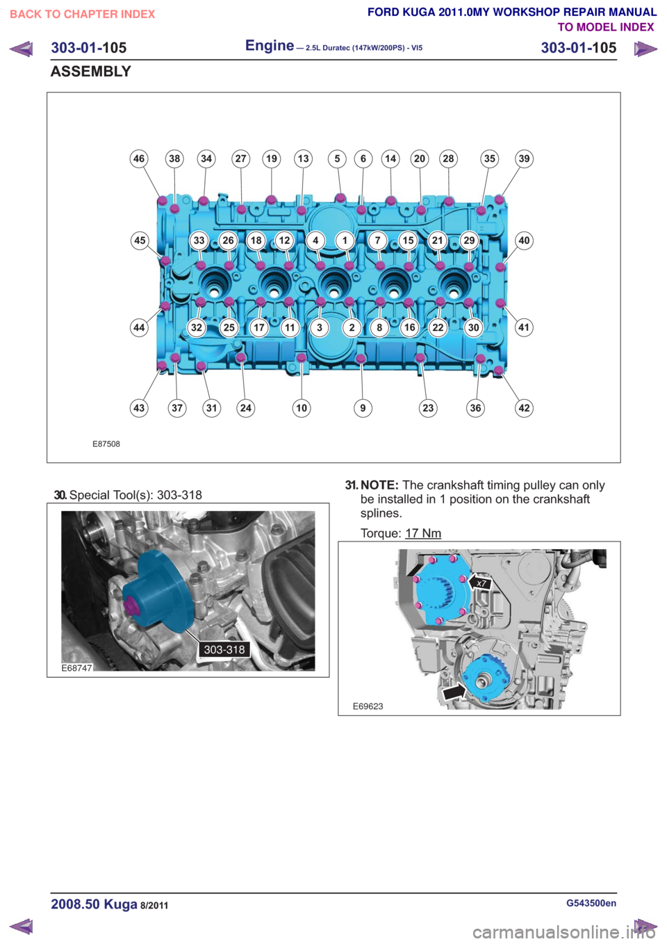
46
45
44
43
3834271913514202839
40
41
423623910243137
635
29211571412182633
30221682311172532
30.Special Tool(s): 303-318
E68747
303-318
31. N O T E : The crankshaft timing pulley can only
be installed in 1 position on the crankshaft
splines.
Torque: 17
Nm
E69623
x7
G543500en2008.50 Kuga8/2011
303-01- 105
Engine— 2.5L Duratec (147kW/200PS) - VI5303-01-
105
ASSEMBLY
TO MODEL INDEX
BACK TO CHAPTER INDEX
FORD KUGA 2011.0MY WORKSHOP REPAIR MANUAL
Page 1681 of 2057
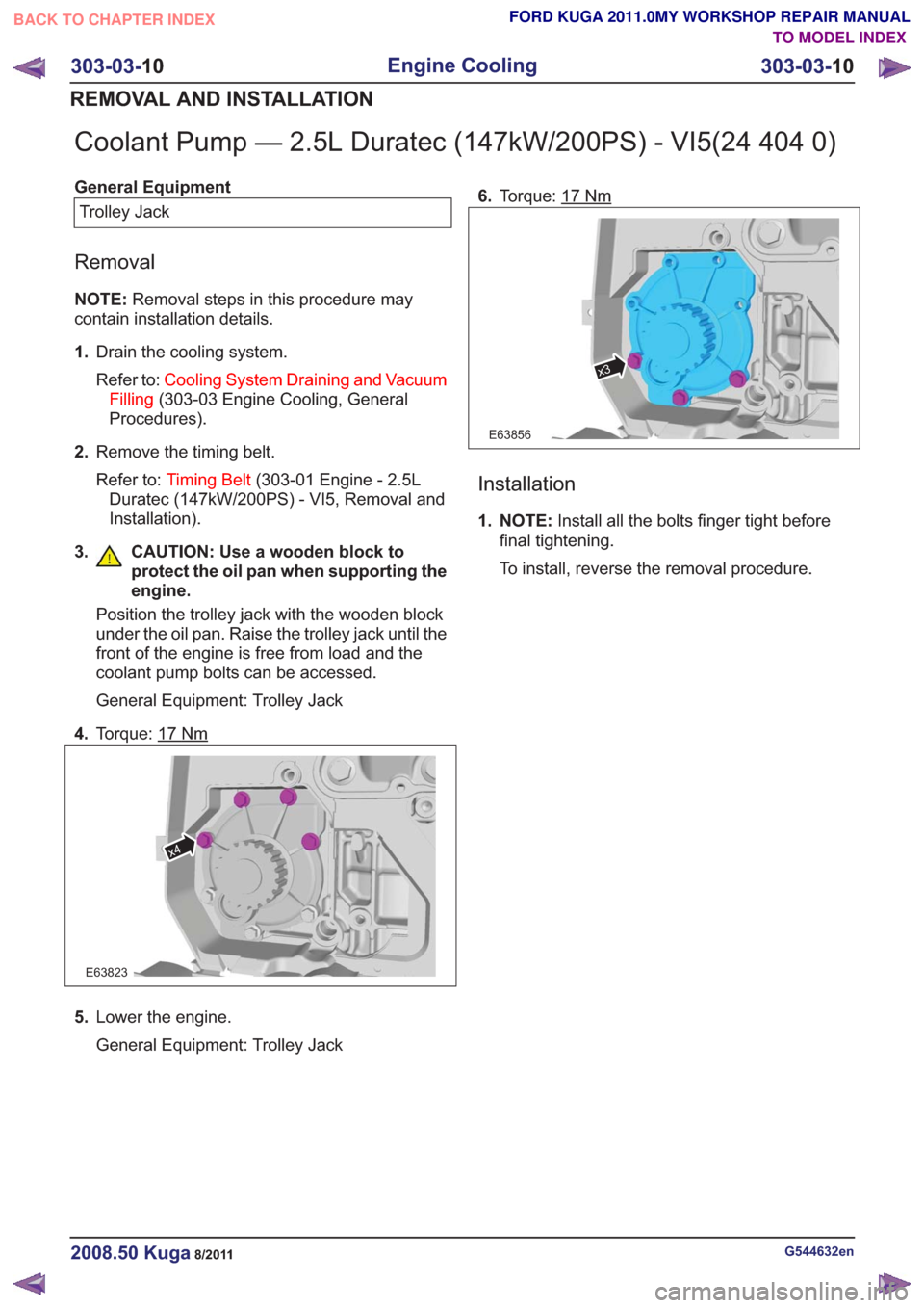
Coolant Pump — 2.5L Duratec (147kW/200PS) - VI5(24 404 0)
General EquipmentTrolley Jack
Removal
NOTE: Removal steps in this procedure may
contain installation details.
1. Drain the cooling system.
Refer to: Cooling System Draining and Vacuum
Filling (303-03 Engine Cooling, General
Procedures).
2. Remove the timing belt.
Refer to: Timing Belt (303-01 Engine - 2.5L
Duratec (147kW/200PS) - VI5, Removal and
Installation).
3. CAUTION: Use a wooden block to protect the oil pan when supporting the
engine.
Position the trolley jack with the wooden block
under the oil pan. Raise the trolley jack until the
front of the engine is free from load and the
coolant pump bolts can be accessed.
General Equipment: Trolley Jack
4. Torque: 17
Nm
E63823
x4
5.Lower the engine.
General Equipment: Trolley Jack 6.
Torque: 17
Nm
x3
E63856
Installation
1. NOTE: Install all the bolts finger tight before
final tightening.
To install, reverse the removal procedure.
G544632en2008.50 Kuga8/2011
303-03- 10
Engine Cooling
303-03- 10
REMOVAL AND INSTALLATION
TO MODEL INDEX
BACK TO CHAPTER INDEX
FORD KUGA 2011.0MY WORKSHOP REPAIR MANUAL
Page 1720 of 2057
Turbocharger – Overview
Turbocharger(s)
CAUTION: Do not switch off the engine
while it is running at high speed. If the
engine is switched off while it is running
at high speed, the turbocharger will
continue to run after the engine oil
pressure has already dropped to zero. This
will cause premature wear in the
turbocharger bearings.
A TC consists of an exhaust turbine located in the
exhaust gas flow, this turbine is connected to a
compressor by a shaft. The turbine is made to
rotate by the exhaust gas flow from the engine and
thus drives the compressor. The compressor
increases the pressure in the engine intake tract
so that a greater mass of air enters the cylinder
during the intake stroke.
The turbine housing of the TC is integrated into the
exhaust manifold. This construction offers
thermodynamic advantages compared with the
usual construction, the maximum exhaust
temperature is up to 1050°C.
The maximum boost pressure is 0.65 bar.
The exhaust manifold is secured to the exhaust
side of the cylinder head with 12 self-locking nuts.
The exhaust manifold gasket is a multi-layer steel
gasket and cannot be reused. In order to
compensate for the thermal expansion of the
exhaust manifold, the flange of the TC is provided
with two grooves.
The TC and the exhaust manifold are joined by a
hose clip. The hose clip must not be loosened or
removed. The TC and the exhaust manifold are
not available as separate replacement parts,
exchange is only possible as a complete unit.
The turbocharger heat shield is secured to the
exhaust manifold by four bolts. Two of the bolts
have spring washers underneath their heads.
During removal, make a note of the installation
location of the spring washers to refer to during
installation.
The recirculated air valve is built into the TC
housing and cannot be changed.
The Ford diagnostic unit can test the operation of
the wastegate control valve using actuator
diagnosis.
The boost pressure regulator is set in the factory.
Adjustments to the boost pressure regulator must never be attempted. A red colored seal is applied
to the adjustment nut of the operating rod, in order
to monitor the factory setting of the boost pressure.
The bearings of the TC are lubricated with engine
oil. The engine oil passes from the cylinder block
through the oil supply pipe to the TC. The oil is
returned to the oil pan through the oil return pipe,
The TC is cooled by the engine coolant circuit.
When installing hoses and lines, make certain that
their ends are free of oil residues and dirt.
G1032425en2008.50 Kuga8/2011
303-04B-
4
Fuel Charging and Controls - Turbocharger
—
2.5L Duratec (147kW/200PS) - VI5
303-04B- 4
DESCRIPTION AND OPERATION
TO MODEL INDEX
BACK TO CHAPTER INDEX
FORD KUGA 2011.0MY WORKSHOP REPAIR MANUAL
Page 1722 of 2057
Description
Item
PWM (pulse width modulation) signal
Comments:from PCM (powertrain control module)
5
Atmospheric pressure
6
Turbocharger boost pressure.
7
from air filter
8
Intake air
9Description
Item
Recirculated air valveRefertoComponentDescription:(page
7)
10
Vacuum line, recirculated air valve
11
to intake manifold
12
Throttle plate
13
Compressor
14
Turbine
15
System Operation
Turbocharger(s)
The TC consists of a turbine and a compressor.
The turbine is driven by the exhaust gas flow. A
common shaft drives the compressor and this then
compresses the intake air.
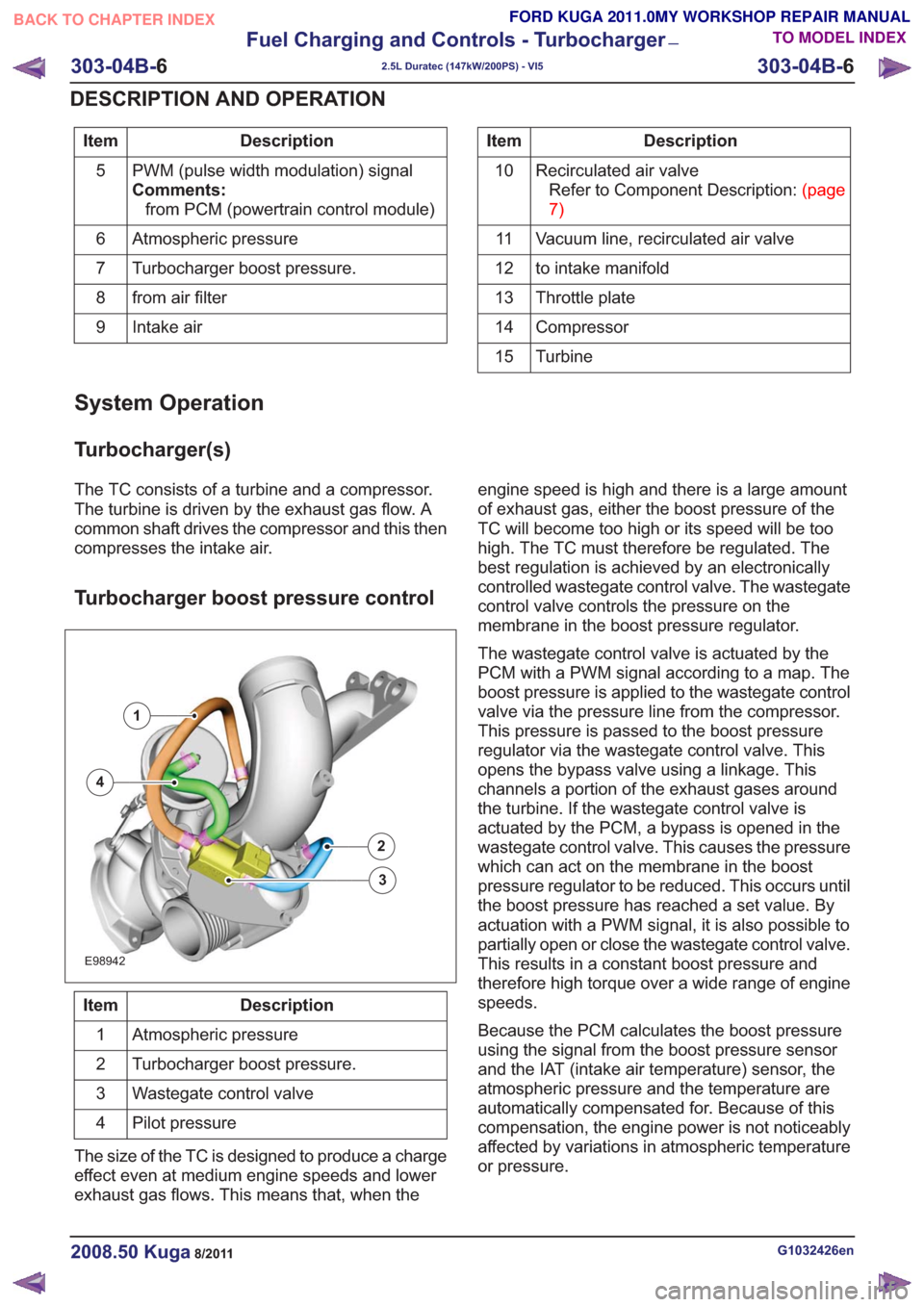
Turbocharger boost pressure control
E98942
1
2
3
4
Description
Item
Atmospheric pressure
1
Turbocharger boost pressure.
2
Wastegate control valve
3
Pilot pressure
4
The size of the TC is designed to produce a charge
effect even at medium engine speeds and lower
exhaust gas flows. This means that, when the engine speed is high and there is a large amount
of exhaust gas, either the boost pressure of the
TC will become too high or its speed will be too
high. The TC must therefore be regulated. The
best regulation is achieved by an electronically
controlled wastegate control valve. The wastegate
control valve controls the pressure on the
membrane in the boost pressure regulator.
The wastegate control valve is actuated by the
PCM with a PWM signal according to a map. The
boost pressure is applied to the wastegate control
valve via the pressure line from the compressor.
This pressure is passed to the boost pressure
regulator via the wastegate control valve. This
opens the bypass valve using a linkage. This
channels a portion of the exhaust gases around
the turbine. If the wastegate control valve is
actuated by the PCM, a bypass is opened in the
wastegate control valve. This causes the pressure
which can act on the membrane in the boost
pressure regulator to be reduced. This occurs until
the boost pressure has reached a set value. By
actuation with a PWM signal, it is also possible to
partially open or close the wastegate control valve.
This results in a constant boost pressure and
therefore high torque over a wide range of engine
speeds.
Because the PCM calculates the boost pressure
using the signal from the boost pressure sensor
and the IAT (intake air temperature) sensor, the
atmospheric pressure and the temperature are
automatically compensated for. Because of this
compensation, the engine power is not noticeably
affected by variations in atmospheric temperature
or pressure.
G1032426en2008.50 Kuga8/2011
303-04B-
6
Fuel Charging and Controls - Turbocharger
—
2.5L Duratec (147kW/200PS) - VI5
303-04B- 6
DESCRIPTION AND OPERATION
TO MODEL INDEX
BACK TO CHAPTER INDEX
FORD KUGA 2011.0MY WORKSHOP REPAIR MANUAL
Page 1723 of 2057
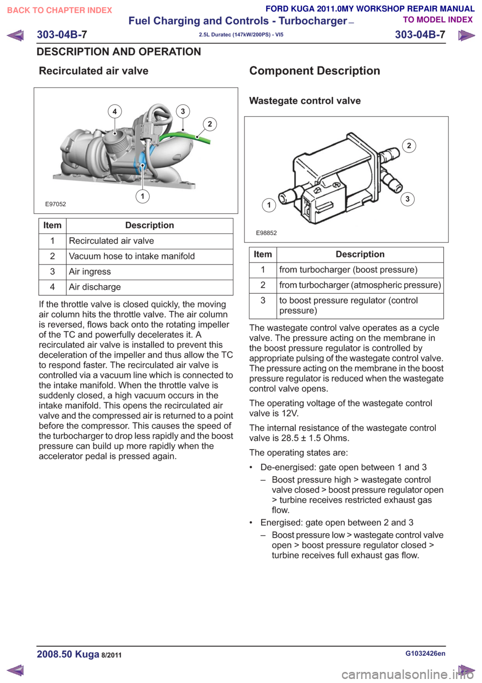
Recirculated air valve
E97052
43
2
1
Description
Item
Recirculated air valve
1
Vacuum hose to intake manifold
2
Air ingress
3
Air discharge
4
If the throttle valve is closed quickly, the moving
air column hits the throttle valve. The air column
is reversed, flows back onto the rotating impeller
of the TC and powerfully decelerates it. A
recirculated air valve is installed to prevent this
deceleration of the impeller and thus allow the TC
to respond faster. The recirculated air valve is
controlled via a vacuum line which is connected to
the intake manifold. When the throttle valve is
suddenly closed, a high vacuum occurs in the
intake manifold. This opens the recirculated air
valve and the compressed air is returned to a point
before the compressor. This causes the speed of
the turbocharger to drop less rapidly and the boost
pressure can build up more rapidly when the
accelerator pedal is pressed again.
Component Description
Wastegate control valve
1
2
3
E98852
Description
Item
from turbocharger (boost pressure)
1
from turbocharger (atmospheric pressure)
2
to boost pressure regulator (control
pressure)
3
The wastegate control valve operates as a cycle
valve. The pressure acting on the membrane in
the boost pressure regulator is controlled by
appropriate pulsing of the wastegate control valve.
The pressure acting on the membrane in the boost
pressure regulator is reduced when the wastegate
control valve opens.
The operating voltage of the wastegate control
valve is 12V.
The internal resistance of the wastegate control
valve is 28.5 ± 1.5 Ohms.
The operating states are:
• De-energised: gate open between 1 and 3 – Boost pressure high > wastegate controlvalve closed > boost pressure regulator open
> turbine receives restricted exhaust gas
flow.
• Energised: gate open between 2 and 3 – Boost pressure low > wastegate control valveopen > boost pressure regulator closed >
turbine receives full exhaust gas flow.
G1032426en2008.50 Kuga8/2011
303-04B- 7
Fuel Charging and Controls - Turbocharger
—
2.5L Duratec (147kW/200PS) - VI5
303-04B- 7
DESCRIPTION AND OPERATION
TO MODEL INDEX
BACK TO CHAPTER INDEX
FORD KUGA 2011.0MY WORKSHOP REPAIR MANUAL
Page 1725 of 2057
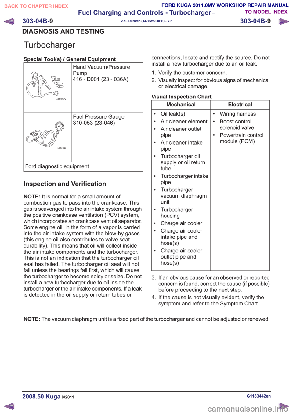
Turbocharger
Special Tool(s) / General EquipmentHand Vacuum/Pressure
Pump
416 - D001 (23 - 036A)
23036A
Fuel Pressure Gauge
310-053 (23-046)
23046
Ford diagnostic equipment
Inspection and Verification
NOTE:It is normal for a small amount of
combustion gas to pass into the crankcase. This
gas is scavenged into the air intake system through
the positive crankcase ventilation (PCV) system,
which incorporates an crankcase vent oil separator.
Some engine oil, in the form of a vapor is carried
into the air intake system with the blow-by gases
(this engine oil also contributes to valve seat
durability). This means that oil will collect inside
the air intake components and the turbocharger.
This is not an indication that the turbocharger oil
seal has failed. The turbocharger oil seal will not
fail unless the bearings fail first, which will cause
the turbocharger to become noisy or seize. Do not
install a new turbocharger due to oil inside the
turbocharger or the air intake components. If a leak
is detected in the oil supply or return tubes or connections, locate and rectify the source. Do not
install a new turbocharger due to an oil leak.
1. Verify the customer concern.
2. Visually inspect for obvious signs of mechanical
or electrical damage.
Visual Inspection Chart
Electrical
Mechanical
• Wiring harness
• Boost controlsolenoid valve
• Powertrain control module (PCM)
• Oil leak(s)
• Air cleaner element
• Air cleaner outlet
pipe
• Air cleaner intake pipe
• Turbocharger oil supply or oil return
tube
• Turbocharger intake pipe
• Turbocharger vacuum diaphragm
unit
• Turbocharger housing
• Charge air cooler
• Charge air cooler intake pipe and
hose(s)
• Charge air cooler outlet pipe and
hose(s)
3. If an obvious cause for an observed or reported concern is found, correct the cause (if possible)
before proceeding to the next step.
4. If the cause is not visually evident, verify the symptom and refer to the Symptom Chart.
NOTE: The vacuum diaphragm unit is a fixed part of the turbocharger and cannot be adjusted or renewed.
G1183442en2008.50 Kuga8/2011
303-04B- 9
Fuel Charging and Controls - Turbocharger
—
2.5L Duratec (147kW/200PS) - VI5
303-04B- 9
DIAGNOSIS AND TESTING
TO MODEL INDEX
BACK TO CHAPTER INDEX
FORD KUGA 2011.0MY WORKSHOP REPAIR MANUAL
Page 1734 of 2057
Accessory Drive
Inspection and Verification
1. Verify the customer concern.
2. Visually inspect for obvious signs of mechanicaldamage.
Visual Inspection Chart
Mechanical
– Damaged or contaminated accessory drive belt or air conditioning (A/C) compressor belt
– Damaged or contaminated pulley(s)
– Incorrect accessory drive belt or A/C compressor belt
– Incorrect fitment of the accessory drive belt or A/C compressor belt
– Accessory drive belt tensioner
– Accessory drive belt idler pulley
– Generator
– A/C compressor
– A/C compressor belt tensioner
– Pulley(s)
– Loose hardware
3. If an obvious cause for an observed or reported concern is found, correct the cause (if possible)
before proceeding to the next step.
Accessory Drive Belt Concerns
CAUTION: Do not lubricate the accessory
drive belt, accessory drive belt tensioner(s)
or idler pulley(s) as potential damage to
the accessory drive belt material
construction, accessory drive belt
tensioner damping mechanism, accessory
drive belt tensioner pulley bearing and idler
pulley(s) bearing may occur.
NOTE: All the diagnosis and testing information
contained within this procedure can be used for
the accessory drive belt and the A/C compressor
belt.
Cracking
Accessory drive belts are made from rubber which
hardens with time and can develop cracks. As the
accessory drive belt runs on the back of some of
the pulleys, the cracks are opened up. Small cracks
are not considered to be a failure of the accessory drive belt. Only if the crack is deep enough to reach
the bottom of the groove to expose the cord or any
chunks are found to be missing from the accessory
drive belt, is the accessory drive belt condition
considered to be unacceptable.
1. Check the accessory drive belt for cracks. If the
damage exceeds the acceptable limit, install a
new accessory drive belt.
REFER to: Accessory Drive Belt (303-05
Accessory Drive - 2.5L Duratec
(147kW/200PS) - VI5, Removal and
Installation).
and/or
REFER to: Air Conditioning (A/C) Compressor
Belt (303-05 Accessory Drive - 2.5L Duratec
(147kW/200PS) - VI5, Removal and
Installation).
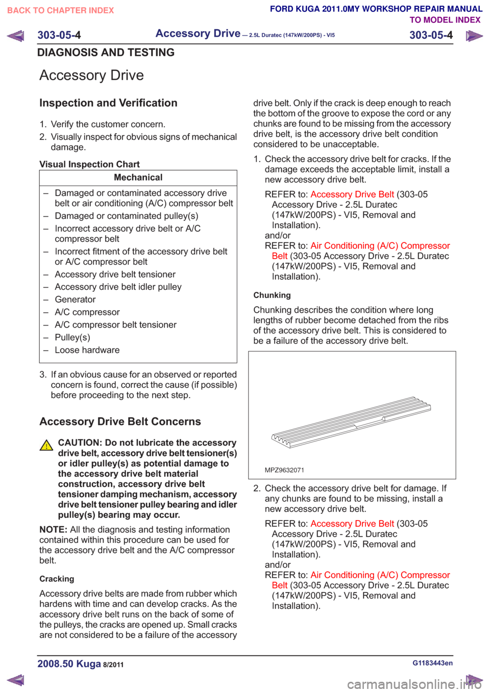
Chunking
Chunking describes the condition where long
lengths of rubber become detached from the ribs
of the accessory drive belt. This is considered to
be a failure of the accessory drive belt.
MPZ9632071
2. Check the accessory drive belt for damage. If any chunks are found to be missing, install a
new accessory drive belt.
REFER to: Accessory Drive Belt (303-05
Accessory Drive - 2.5L Duratec
(147kW/200PS) - VI5, Removal and
Installation).
and/or
REFER to: Air Conditioning (A/C) Compressor
Belt (303-05 Accessory Drive - 2.5L Duratec
(147kW/200PS) - VI5, Removal and
Installation).
G1183443en2008.50 Kuga8/2011
303-05- 4
Accessory Drive— 2.5L Duratec (147kW/200PS) - VI5303-05-
4
DIAGNOSIS AND TESTING
TO MODEL INDEX
BACK TO CHAPTER INDEX
FORD KUGA 2011.0MY WORKSHOP REPAIR MANUAL
Page 1735 of 2057
Pilling
Pilling is dust that forms in between the ribs of the
accessory drive belt from rubber that is worn off
the accessory drive belt when it is new. There may
also be loose particles left on the accessory drive
belt during the manufacturing process. These are
worn off and form into small balls of rubber that
then get trapped in the grooves of the accessory
drive belt. This condition will usually clear itself
within 4800 km - 8000 km (3000 miles - 5000 miles)
of normal driving.
VUE0037805
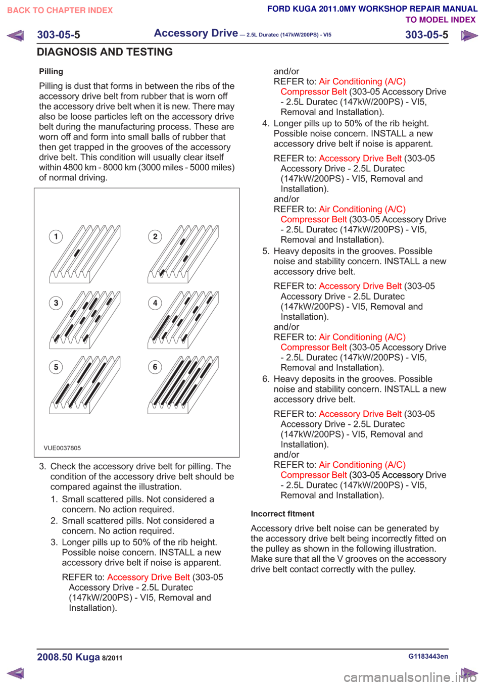
3. Check the accessory drive belt for pilling. Thecondition of the accessory drive belt should be
compared against the illustration.
1. Small scattered pills. Not considered a concern. No action required.
2. Small scattered pills. Not considered a concern. No action required.
3. Longer pills up to 50% of the rib height. Possible noise concern. INSTALL a new
accessory drive belt if noise is apparent.
REFER to: Accessory Drive Belt (303-05
Accessory Drive - 2.5L Duratec
(147kW/200PS) - VI5, Removal and
Installation). and/or
REFER to:
Air Conditioning (A/C)
Compressor Belt (303-05 Accessory Drive
- 2.5L Duratec (147kW/200PS) - VI5,
Removal and Installation).
4. Longer pills up to 50% of the rib height. Possible noise concern. INSTALL a new
accessory drive belt if noise is apparent.
REFER to: Accessory Drive Belt (303-05
Accessory Drive - 2.5L Duratec
(147kW/200PS) - VI5, Removal and
Installation).
and/or
REFER to: Air Conditioning (A/C)
Compressor Belt (303-05 Accessory Drive
- 2.5L Duratec (147kW/200PS) - VI5,
Removal and Installation).
5. Heavy deposits in the grooves. Possible noise and stability concern. INSTALL a new
accessory drive belt.
REFER to: Accessory Drive Belt (303-05
Accessory Drive - 2.5L Duratec
(147kW/200PS) - VI5, Removal and
Installation).
and/or
REFER to: Air Conditioning (A/C)
Compressor Belt (303-05 Accessory Drive
- 2.5L Duratec (147kW/200PS) - VI5,
Removal and Installation).
6. Heavy deposits in the grooves. Possible noise and stability concern. INSTALL a new
accessory drive belt.
REFER to: Accessory Drive Belt (303-05
Accessory Drive - 2.5L Duratec
(147kW/200PS) - VI5, Removal and
Installation).
and/or
REFER to: Air Conditioning (A/C)
Compressor Belt (303-05 AccessoryDrive
- 2.5L Duratec (147kW/200PS) - VI5,
Removal and Installation).
Incorrect fitment
Accessory drive belt noise can be generated by
the accessory drive belt being incorrectly fitted on
the pulley as shown in the following illustration.
Make sure that all the V grooves on the accessory
drive belt contact correctly with the pulley.
G1183443en2008.50 Kuga8/2011
303-05- 5
Accessory Drive— 2.5L Duratec (147kW/200PS) - VI5303-05-
5
DIAGNOSIS AND TESTING
TO MODEL INDEX
BACK TO CHAPTER INDEX
FORD KUGA 2011.0MY WORKSHOP REPAIR MANUAL
Page 1737 of 2057
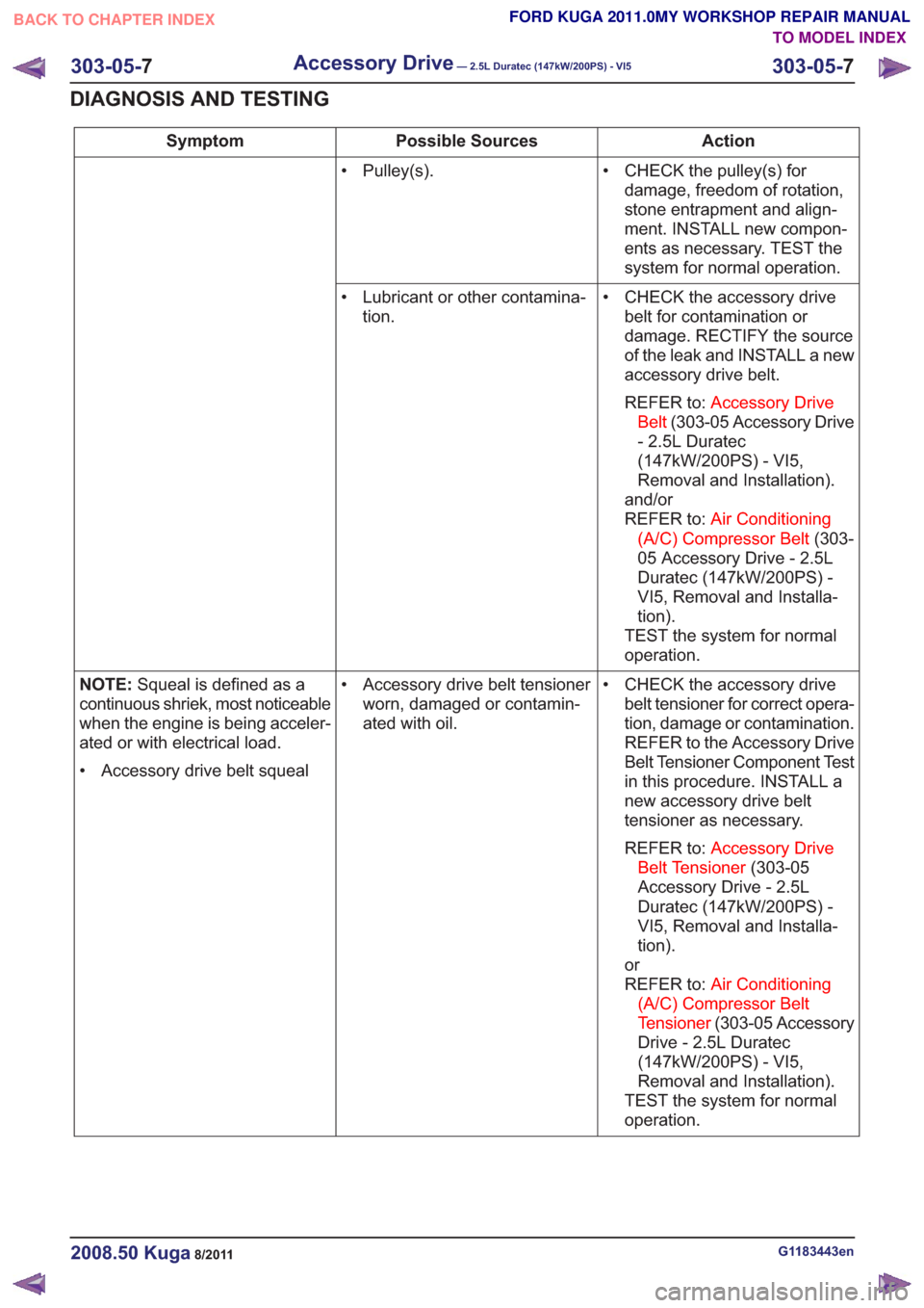
Action
Possible Sources
Symptom
• CHECK the pulley(s) fordamage, freedom of rotation,
stone entrapment and align-
ment. INSTALL new compon-
ents as necessary. TEST the
system for normal operation.
• Pulley(s).
• CHECK the accessory drivebelt for contamination or
damage. RECTIFY the source
of the leak and INSTALL a new
accessory drive belt.
REFER to: Accessory Drive
Belt (303-05 Accessory Drive
- 2.5L Duratec
(147kW/200PS) - VI5,
Removal and Installation).
and/or
REFER to: Air Conditioning
(A/C) Compressor Belt (303-
05 Accessory Drive - 2.5L
Duratec (147kW/200PS) -
VI5, Removal and Installa-
tion).
TEST the system for normal
operation.
• Lubricant or other contamina-
tion.
• CHECK the accessory drivebelt tensioner for correct opera-
tion, damage or contamination.
REFER to the Accessory Drive
Belt Tensioner Component Test
in this procedure. INSTALL a
new accessory drive belt
tensioner as necessary.
REFER to: Accessory Drive
Belt Tensioner (303-05
Accessory Drive - 2.5L
Duratec (147kW/200PS) -
VI5, Removal and Installa-
tion).
or
REFER to: Air Conditioning
(A/C) Compressor Belt
Tensioner (303-05 Accessory
Drive - 2.5L Duratec
(147kW/200PS) - VI5,
Removal and Installation).
TEST the system for normal
operation.
• Accessory drive belt tensioner
worn, damaged or contamin-
ated with oil.
NOTE:
Squeal is defined as a
continuous shriek, most noticeable
when the engine is being acceler-
ated or with electrical load.
• Accessory drive belt squeal
G1183443en2008.50 Kuga8/2011
303-05- 7
Accessory Drive— 2.5L Duratec (147kW/200PS) - VI5303-05-
7
DIAGNOSIS AND TESTING
TO MODEL INDEX
BACK TO CHAPTER INDEX
FORD KUGA 2011.0MY WORKSHOP REPAIR MANUAL
Page 1739 of 2057
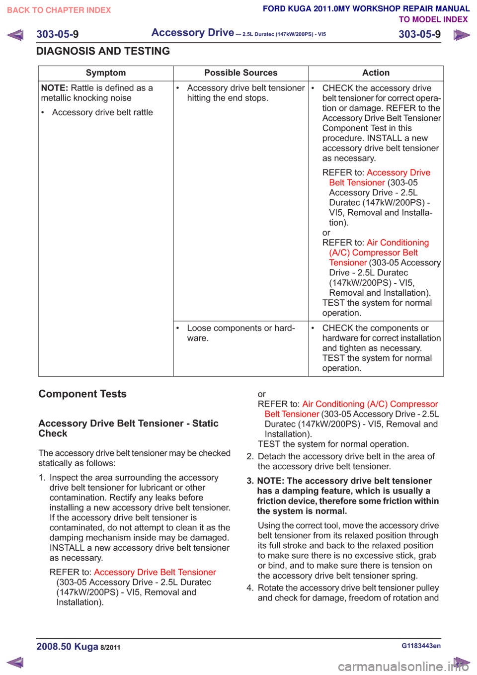
Action
Possible Sources
Symptom
• CHECK the accessory drivebelt tensioner for correct opera-
tion or damage. REFER to the
Accessory Drive Belt Tensioner
Component Test in this
procedure. INSTALL a new
accessory drive belt tensioner
as necessary.
REFER to: Accessory Drive
Belt Tensioner (303-05
Accessory Drive - 2.5L
Duratec (147kW/200PS) -
VI5, Removal and Installa-
tion).
or
REFER to: Air Conditioning
(A/C) Compressor Belt
Tensioner (303-05 Accessory
Drive - 2.5L Duratec
(147kW/200PS) - VI5,
Removal and Installation).
TEST the system for normal
operation.
• Accessory drive belt tensioner
hitting the end stops.
NOTE:
Rattle is defined as a
metallic knocking noise
• Accessory drive belt rattle
• CHECK the components orhardware for correct installation
and tighten as necessary.
TEST the system for normal
operation.
• Loose components or hard-
ware.
Component Tests
Accessory Drive Belt Tensioner - Static
Check
The accessory drive belt tensioner may be checked
statically as follows:
1. Inspect the area surrounding the accessorydrive belt tensioner for lubricant or other
contamination. Rectify any leaks before
installing a new accessory drive belt tensioner.
If the accessory drive belt tensioner is
contaminated, do not attempt to clean it as the
damping mechanism inside may be damaged.
INSTALL a new accessory drive belt tensioner
as necessary.
REFER to: Accessory Drive Belt Tensioner
(303-05 Accessory Drive - 2.5L Duratec
(147kW/200PS) - VI5, Removal and
Installation). or
REFER to:
Air Conditioning (A/C) Compressor
Belt Tensioner (303-05 Accessory Drive - 2.5L
Duratec (147kW/200PS) - VI5, Removal and
Installation).
TEST the system for normal operation.
2. Detach the accessory drive belt in the area of the accessory drive belt tensioner.
3. NOTE: The accessory drive belt tensioner has a damping feature, which is usually a
friction device, therefore some friction within
the system is normal.
Using the correct tool, move the accessory drive
belt tensioner from its relaxed position through
its full stroke and back to the relaxed position
to make sure there is no excessive stick, grab
or bind, and to make sure there is tension on
the accessory drive belt tensioner spring.
4. Rotate the accessory drive belt tensioner pulley and check for damage, freedom of rotation and
G1183443en2008.50 Kuga8/2011
303-05- 9
Accessory Drive— 2.5L Duratec (147kW/200PS) - VI5303-05-
9
DIAGNOSIS AND TESTING
TO MODEL INDEX
BACK TO CHAPTER INDEX
FORD KUGA 2011.0MY WORKSHOP REPAIR MANUAL