oil change FORD KUGA 2011 1.G Workshop Manual
[x] Cancel search | Manufacturer: FORD, Model Year: 2011, Model line: KUGA, Model: FORD KUGA 2011 1.GPages: 2057
Page 51 of 2057
The use of drum cleaning units, vacuum cleaning
or damp wiping is preferred.
Asbestos dust waste should be dampened, placed
in a sealed container and marked for safe disposal.
If any cutting or drilling is attempted on materials
containing asbestos the item should be dampened
and only hand tools or low speed power tools used.
Battery Acids
See also Acids and Alkalis.
For additional information, refer to:Battery and
Battery Charging Health and Safety Precautions
(100-00 General Information, Description and
Operation).
Brake and Clutch Linings and Pads
See Asbestos.
Brake Fluids (Polyalkylene Glycols)
See also Fire.
For additional information, refer to: Brake System
Health and Safety Precautions (100-00 General
Information, Description and Operation).
Brazing
See Welding.
Chemical Materials
See also Legal Aspects.
Chemical materials such as solvents, sealers,
adhesives, paints, resin foams, battery acids,
antifreeze, brake fluids, fuels, oils and grease
should always be used with caution and stored and
handled with care. They may be toxic, harmful,
corrosive, irritant or highly flammable and give rise
to hazardous fumes and dusts.
The effects of excessive exposure to chemicals
may be immediate or delayed; briefly experienced
or permanent; cumulative; superficial; life
threatening; or may reduce life expectancy.
Chemical Materials - Do's
– Do carefully read and observe hazard and precaution warnings given on material
containers (labels) and in any accompanying
leaflets, posters or other instructions. Material
health and safety data sheets can be obtained
from manufacturers.
– Do remove chemical materials from the skin and clothing as soon as practicable after soiling.
Change heavily soiled clothing and have it
cleaned.
– Do organize work practices and protective clothing to avoid soiling of the skin and eyes;
breathing vapors, aerosols, dusts or fumes;
inadequate container labeling; fire and explosion
hazards.
– Do wash before job breaks, before eating, smoking, drinking or using toilet facilities when
handling chemical materials.
– Do keep work areas clean, uncluttered and free of spills.
– Do store chemical materials according to national and local regulations.
– Do keep chemical materials out of the reach of children.
Chemical Materials - Do Nots
– Do not mix chemical materials except under themanufacturers instructions; some chemicals can
form other toxic or harmful chemicals, give off
toxic or harmful fumes or become explosive
when mixed together.
– Do not spray chemical materials, particularly those based on solvents, in confined spaces,
for example when people are inside a vehicle.
– Do not apply heat or flame to chemical materials except under the manufacturers instructions.
Some are highly flammable and some may
release toxic or harmful fumes.
– Do not leave containers open. Fumes given off can build up to toxic, harmful or explosive
concentrations. Some fumes are heavier than
air and will accumulate in confined areas such
as pits.
– Do not transfer chemical materials to unlabelled containers.
– Do not clean hands or clothing with chemicals. Chemicals, particularly solvents and fuels, will
dry the skin and may cause irritation leading to
G566527en2008.50 Kuga8/2011
100-00- 44
General Information
100-00- 44
DESCRIPTION AND OPERATION
TO MODEL INDEX
BACK TO CHAPTER INDEX
FORD KUGA 2011.0MY WORKSHOP REPAIR MANUAL
Page 187 of 2057
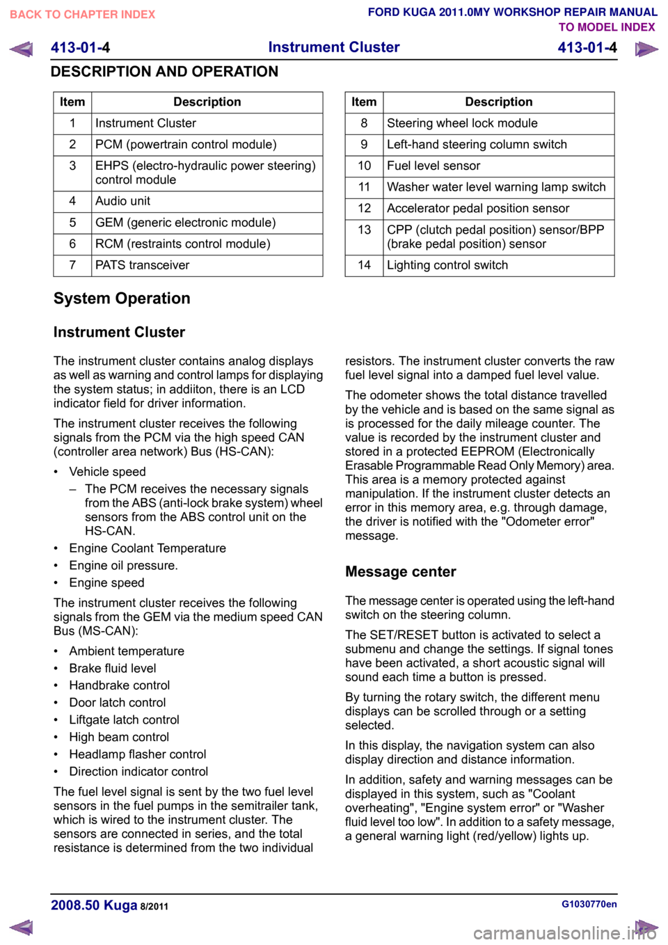
Description
Item
Instrument Cluster
1
PCM (powertrain control module)
2
EHPS (electro-hydraulic power steering)
control module
3
Audio unit
4
GEM (generic electronic module)
5
RCM (restraints control module)
6
PATS transceiver
7 Description
Item
Steering wheel lock module
8
Left-hand steering column switch
9
Fuel level sensor
10
Washer water level warning lamp switch
11
Accelerator pedal position sensor
12
CPP (clutch pedal position) sensor/BPP
(brake pedal position) sensor
13
Lighting control switch
14
System Operation
Instrument Cluster
The instrument cluster contains analog displays
as well as warning and control lamps for displaying
the system status; in addiiton, there is an LCD
indicator field for driver information.
The instrument cluster receives the following
signals from the PCM via the high speed CAN
(controller area network) Bus (HS-CAN):
• Vehicle speed – The PCM receives the necessary signalsfrom the ABS (anti-lock brake system) wheel
sensors from the ABS control unit on the
HS-CAN.
• Engine Coolant Temperature
• Engine oil pressure.
• Engine speed
The instrument cluster receives the following
signals from the GEM via the medium speed CAN
Bus (MS-CAN):
• Ambient temperature
• Brake fluid level
• Handbrake control
• Door latch control
• Liftgate latch control
• High beam control
• Headlamp flasher control
• Direction indicator control
The fuel level signal is sent by the two fuel level
sensors in the fuel pumps in the semitrailer tank,
which is wired to the instrument cluster. The
sensors are connected in series, and the total
resistance is determined from the two individual resistors. The instrument cluster converts the raw
fuel level signal into a damped fuel level value.
The odometer shows the total distance travelled
by the vehicle and is based on the same signal as
is processed for the daily mileage counter. The
value is recorded by the instrument cluster and
stored in a protected EEPROM (Electronically
Erasable Programmable Read Only Memory) area.
This area is a memory protected against
manipulation. If the instrument cluster detects an
error in this memory area, e.g. through damage,
the driver is notified with the "Odometer error"
message.
Message center
The message center is operated using the left-hand
switch on the steering column.
The SET/RESET button is activated to select a
submenu and change the settings. If signal tones
have been activated, a short acoustic signal will
sound each time a button is pressed.
By turning the rotary switch, the different menu
displays can be scrolled through or a setting
selected.
In this display, the navigation system can also
display direction and distance information.
In addition, safety and warning messages can be
displayed in this system, such as "Coolant
overheating", "Engine system error" or "Washer
fluid level too low". In addition to a safety message,
a general warning light (red/yellow) lights up.
G1030770en
2008.50 Kuga 8/2011 413-01-4
Instrument Cluster
413-01-4
DESCRIPTION AND OPERATIONTO MODEL INDEX
BACK TO CHAPTER INDEX
FORD KUGA 2011.0MY WORKSHOP REPAIR MANUAL
Page 196 of 2057

SECTION 413-09 Warning Devices
VEHICLE APPLICATION:
2008.50 Kuga
PAGE
CONTENTS
DIAGNOSIS AND TESTING
413-09-2
Warning Devices.................................................................................................................
413-09-2
Inspection and Verification..................................................................................................
GENERAL PROCEDURES 413-09-3
Safety Belt Minder Deactivating/Activating.........................................................................
413-09-3
Preparation .........................................................................................................................
413-09-3
Deactivating/Activating .......................................................................................................
413-09-4
Oil Change Indicator Reset................................................................................................ 413-09-1
Warning Devices
413-09-1
.TO MODEL INDEX
BACK TO CHAPTER INDEX
FORD KUGA 2011.0MY WORKSHOP REPAIR MANUAL
Page 199 of 2057

Oil Change Indicator Reset
1.
Turn the ignition key to position II without
cranking the engine.
2. Simultaneously press and hold the accelerator
pedal and the brake pedal for approximately 15
seconds until the oil change reminder indicator
starts to flash or the "Service Oil Reset
Complete" message appears in the information
and message center (if equipped).
3. Release the pedals.
4. Check that the oil change reminder indicator
has turned off or that there is no "Service Oil"
message in the information and message center
(if equipped). If the oil change reminder indicator
is still illuminated or the "Service Oil" message
is still displayed, turn the ignition key to position
0 and repeat the procedure from Step 1. If it has
turned off or the "Service Oil" message has
disappeared, proceed to Step 5.
5. Turn the ignition key to position 0 and leave it
there for at least 2 minutes so that the
powertrain control module (PCM) fully powers
down and updates the non-volatile memory
(NVM) in the PCM.
6. Turn the ignition key to position II without
cranking the engine and check that the oil
change reminder indicator is not illuminated or
that there is no "Service Oil" message displayed.
7. Turn the ignition key to position 0. G898940en
2008.50 Kuga 8/2011 413-09-4
Warning Devices
413-09-4
GENERAL PROCEDURESTO MODEL INDEX
BACK TO CHAPTER INDEX
FORD KUGA 2011.0MY WORKSHOP REPAIR MANUAL
Page 1168 of 2057
3. If a new lower arm is installed it will benecessary to check and adjust the front wheel
alignment.
REFER to: Front Toe Adjustment (204-00
Suspension System - General Information,
General Procedures)
/ Rear Toe Adjustment (204-00 Suspension
System - General Information, General
Procedures).
Strut or Shock Absorber Inspection
NOTE: Inspect the struts or shock absorber for
signs of oil weepage or leaks. Make sure that the
oil is not from another source.
Weepage:
• deposits a thin film of oil on the strut and spring assembly or shock absorber.
• is normally noticed due to a collection of dust on the strut and spring assembly or shock
absorber.
• occurs during the normal running-in period of 4800 - 8050 km. After this period no new signs
of oil should be visible.
• does not require new struts or shock absorbers to be installed.
Leakage:
• covers the entire strut and spring assembly or shock absorber with oil.
• will drip oil onto the surrounding suspension components.
• requires new struts or shock absorbers to be installed.
Strut or Shock Absorber Testing
NOTE: Struts or shock absorbers must be tested
in the vertical position.
1. Remove both strut and spring assemblies or shock absorbers. The piston rods should extend.
• Disassemble the strut and spring assemblies.
REFER to: Front Strut and Spring Assembly
(204-01 Front Suspension, Removal and
Installation).
2. Compress the piston rods. Both piston rods should offer the same resistance when
compressing.
3. Compress and release the piston rods. The piston rods should extent equally. 4. Compress and pull the piston rod in the vertical
position. Feel if the resistance force at the point
of direction change-over is perceptible without
a lag. If a lag is perceptible it is an indication of
damper valve damage and new struts or shock
absorbers must be installed. REFER to:
Front Strut and Spring Assembly (204-01 Front
Suspension, Removal and Installation),
Spring (204-02 Rear Suspension, Removal and
Installation).
Load-Levelling Shock Absorber
1. With the vehicle unladen, measure and note the dimensions between the base of the wheel rim
and the top of the rear fender on both sides.
• The measurements on both sides should be approximately equal.
2. With a load of 4 average size adults and a 100 kg weight, measure and note the dimensions
between the base of the wheel rim and the top
of the rear fender on both sides.
3. NOTE: Due to the internal ratchet mechanism of the suspension components, the height
of the rear of the vehicle should rise during
the road test.
With a load of 4 average size adults and a 100
kg weight, drive the vehicle for 3 km on a road
of normal condition.
4. With a load of 4 average size adults and a 100 kg weight, measure and note the dimensions
between the base of the wheel rim and the top
of the rear fender on both sides.
5. If the dimensions on both sides are no longer approximately equal, install new load levelling
shock absorbers.
REFER to: Spring(204-02 Rear Suspension,
Removal and Installation).
6. NOTE: Due to the internal ratchet mechanism of the suspension components, the height
of the rear of the vehicle should rise during
the road test.
If the dimensions are approximately equal,
unload the vehicle and drive the vehicle for 3
km on a road of normal condition.
7. With the vehicle unladen, measure and note the dimensions between the base of the wheel rim
and the top of the rear fender on both sides.
Check the final dimensions with the original
dimensions taken in the unladen condition.
G1080717en2008.50 Kuga8/2011
204-00- 13
Suspension System - General Information
204-00- 13
DIAGNOSIS AND TESTING
TO MODEL INDEX
BACK TO CHAPTER INDEX
FORD KUGA 2011.0MY WORKSHOP REPAIR MANUAL
Page 1264 of 2057
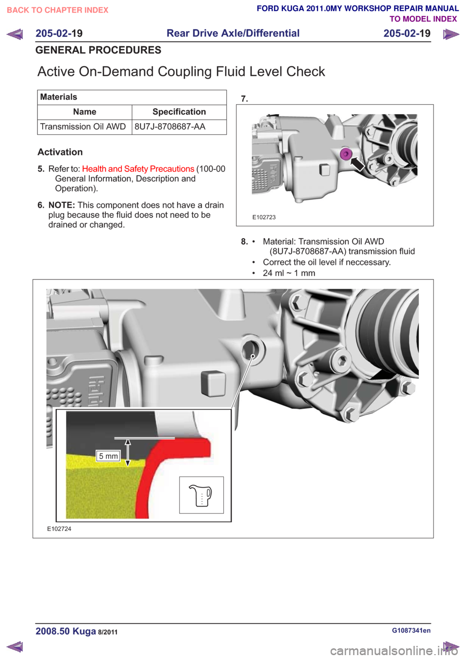
Active On-Demand Coupling Fluid Level Check
MaterialsSpecification
Name
8U7J-8708687-AA
Transmission Oil AWD
Activation
5. Refer to: Health and Safety Precautions (100-00
General Information, Description and
Operation).
6. NOTE: This component does not have a drain
plug because the fluid does not need to be
drained or changed. 7.
E102723
8.
Material: Transmission Oil AWD
(8U7J-8708687-AA) transmission fluid
•
• Correct the oil level if neccessary.
• 24ml~1mm
5mm5mm
E102724
G1087341en2008.50 Kuga8/2011
205-02-
19
Rear Drive Axle/Differential
205-02- 19
GENERAL PROCEDURES
TO MODEL INDEX
BACK TO CHAPTER INDEX
FORD KUGA 2011.0MY WORKSHOP REPAIR MANUAL
Page 1518 of 2057
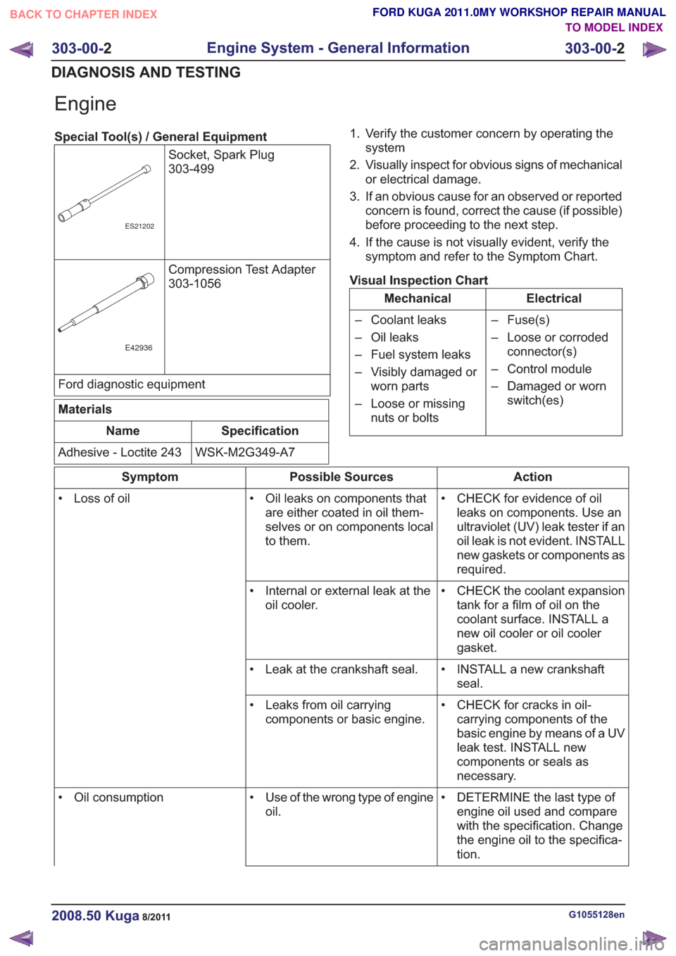
Engine
Special Tool(s) / General EquipmentSocket, Spark Plug
303-499
ES21202
Compression Test Adapter
303-1056
E42936
Ford diagnostic equipment
Materials
Specification
Name
WSK-M2G349-A7
Adhesive - Loctite 243 1. Verify the customer concern by operating the
system
2. Visually inspect for obvious signs of mechanical or electrical damage.
3. If an obvious cause for an observed or reported concern is found, correct the cause (if possible)
before proceeding to the next step.
4. If the cause is not visually evident, verify the symptom and refer to the Symptom Chart.
Visual Inspection Chart
Electrical
Mechanical
– Fuse(s)
– Loose or corrodedconnector(s)
– Control module
– Damaged or worn switch(es)
– Coolant leaks
– Oil leaks
– Fuel system leaks
– Visibly damaged or
worn parts
– Loose or missing nuts or bolts
Action
Possible Sources
Symptom
• CHECK for evidence of oilleaks on components. Use an
ultraviolet (UV) leak tester if an
oil leak is not evident. INSTALL
new gaskets or components as
required.
• Oil leaks on components that
are either coated in oil them-
selves or on components local
to them.
• Loss of oil
• CHECK the coolant expansiontank for a film of oil on the
coolant surface. INSTALL a
new oil cooler or oil cooler
gasket.
• Internal or external leak at the
oil cooler.
• INSTALL a new crankshaftseal.
• Leak at the crankshaft seal.
• CHECK for cracks in oil-carrying components of the
basic engine by means of a UV
leak test. INSTALL new
components or seals as
necessary.
• Leaks from oil carrying
components or basic engine.
• DETERMINE the last type ofengine oil used and compare
with the specification. Change
the engine oil to the specifica-
tion.
• Use of the wrong type of engine
oil.
• Oil consumption
G1055128en2008.50 Kuga8/2011
303-00-
2
Engine System - General Information
303-00- 2
DIAGNOSIS AND TESTING
TO MODEL INDEX
BACK TO CHAPTER INDEX
FORD KUGA 2011.0MY WORKSHOP REPAIR MANUAL
Page 1546 of 2057
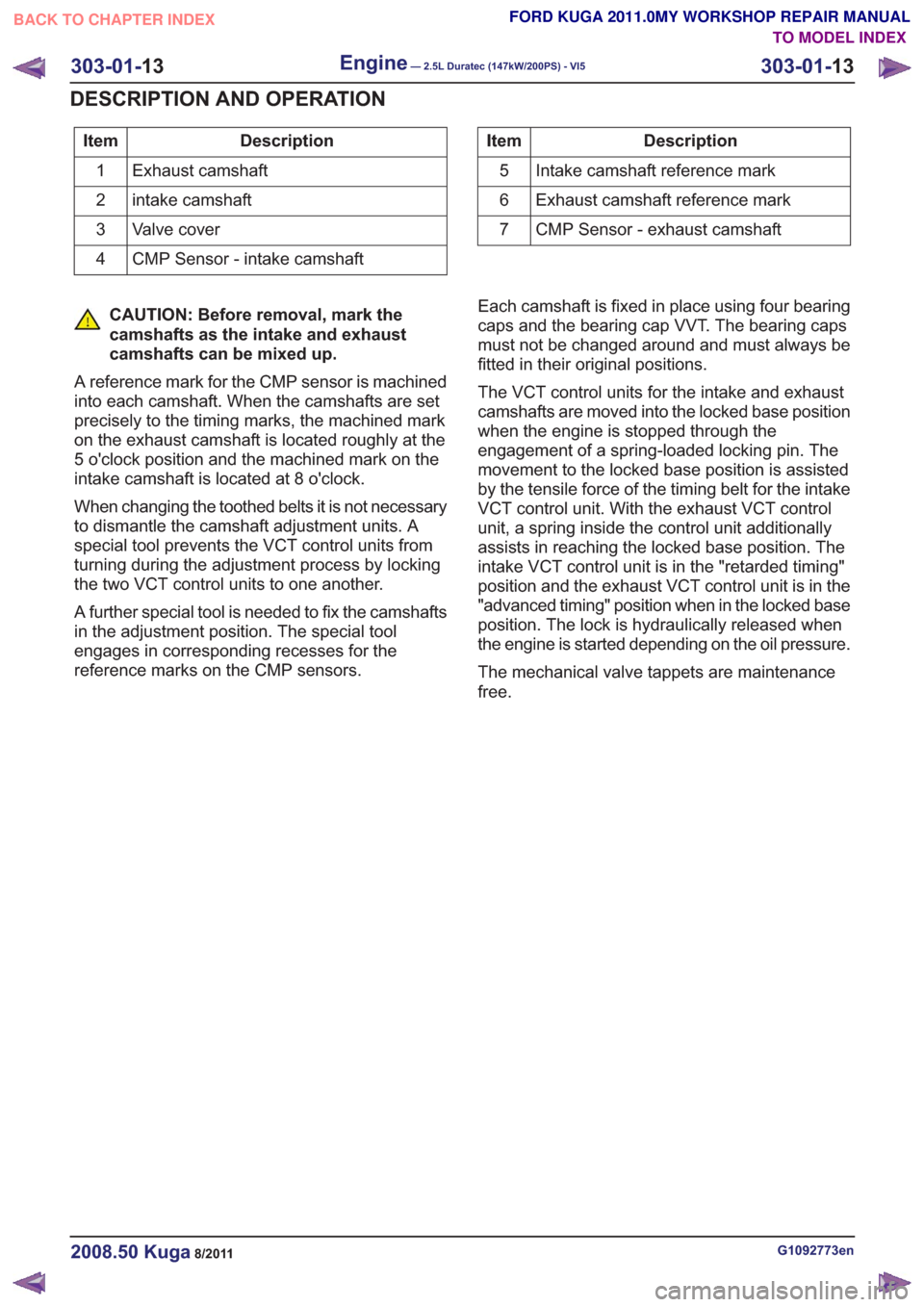
Description
Item
Exhaust camshaft
1
intake camshaft
2
Valve cover
3
CMP Sensor - intake camshaft
4Description
Item
Intake camshaft reference mark
5
Exhaust camshaft reference mark
6
CMP Sensor - exhaust camshaft
7
CAUTION: Before removal, mark the
camshafts as the intake and exhaust
camshafts can be mixed up.
A reference mark for the CMP sensor is machined
into each camshaft. When the camshafts are set
precisely to the timing marks, the machined mark
on the exhaust camshaft is located roughly at the
5 o'clock position and the machined mark on the
intake camshaft is located at 8 o'clock.
When changing the toothed belts it is not necessary
to dismantle the camshaft adjustment units. A
special tool prevents the VCT control units from
turning during the adjustment process by locking
the two VCT control units to one another.
A further special tool is needed to fix the camshafts
in the adjustment position. The special tool
engages in corresponding recesses for the
reference marks on the CMP sensors. Each camshaft is fixed in place using four bearing
caps and the bearing cap VVT. The bearing caps
must not be changed around and must always be
fitted in their original positions.
The VCT control units for the intake and exhaust
camshafts are moved into the locked base position
when the engine is stopped through the
engagement of a spring-loaded locking pin. The
movement to the locked base position is assisted
by the tensile force of the timing belt for the intake
VCT control unit. With the exhaust VCT control
unit, a spring inside the control unit additionally
assists in reaching the locked base position. The
intake VCT control unit is in the "retarded timing"
position and the exhaust VCT control unit is in the
"advanced timing" position when in the locked base
position. The lock is hydraulically released when
the engine is started depending on the oil pressure.
The mechanical valve tappets are maintenance
free.
G1092773en2008.50 Kuga8/2011
303-01-
13
Engine— 2.5L Duratec (147kW/200PS) - VI5303-01-
13
DESCRIPTION AND OPERATION
TO MODEL INDEX
BACK TO CHAPTER INDEX
FORD KUGA 2011.0MY WORKSHOP REPAIR MANUAL
Page 1720 of 2057
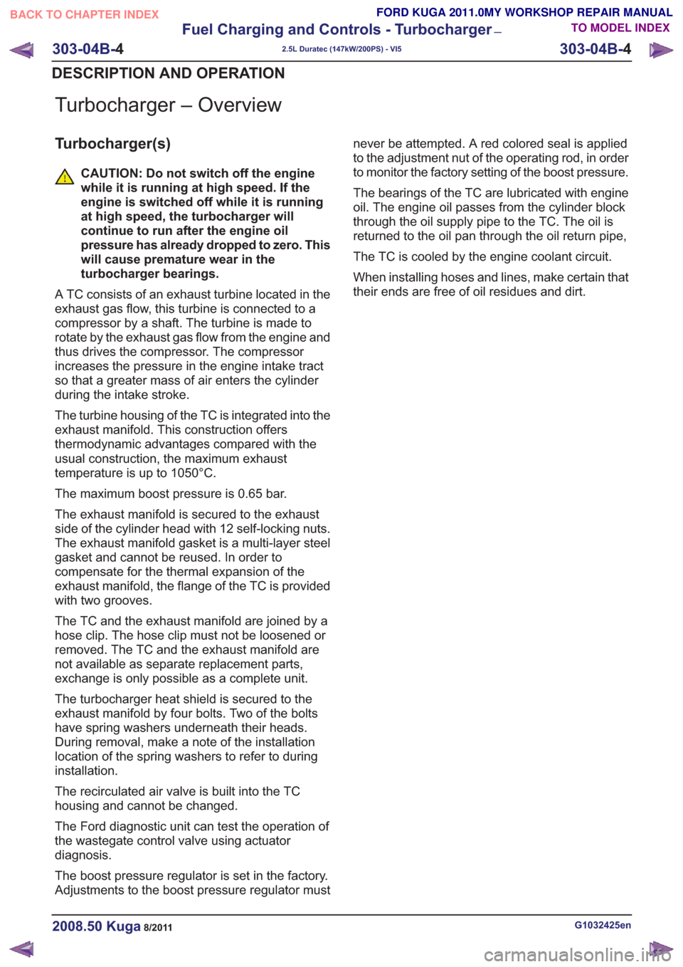
Turbocharger – Overview
Turbocharger(s)
CAUTION: Do not switch off the engine
while it is running at high speed. If the
engine is switched off while it is running
at high speed, the turbocharger will
continue to run after the engine oil
pressure has already dropped to zero. This
will cause premature wear in the
turbocharger bearings.
A TC consists of an exhaust turbine located in the
exhaust gas flow, this turbine is connected to a
compressor by a shaft. The turbine is made to
rotate by the exhaust gas flow from the engine and
thus drives the compressor. The compressor
increases the pressure in the engine intake tract
so that a greater mass of air enters the cylinder
during the intake stroke.
The turbine housing of the TC is integrated into the
exhaust manifold. This construction offers
thermodynamic advantages compared with the
usual construction, the maximum exhaust
temperature is up to 1050°C.
The maximum boost pressure is 0.65 bar.
The exhaust manifold is secured to the exhaust
side of the cylinder head with 12 self-locking nuts.
The exhaust manifold gasket is a multi-layer steel
gasket and cannot be reused. In order to
compensate for the thermal expansion of the
exhaust manifold, the flange of the TC is provided
with two grooves.
The TC and the exhaust manifold are joined by a
hose clip. The hose clip must not be loosened or
removed. The TC and the exhaust manifold are
not available as separate replacement parts,
exchange is only possible as a complete unit.
The turbocharger heat shield is secured to the
exhaust manifold by four bolts. Two of the bolts
have spring washers underneath their heads.
During removal, make a note of the installation
location of the spring washers to refer to during
installation.
The recirculated air valve is built into the TC
housing and cannot be changed.
The Ford diagnostic unit can test the operation of
the wastegate control valve using actuator
diagnosis.
The boost pressure regulator is set in the factory.
Adjustments to the boost pressure regulator must never be attempted. A red colored seal is applied
to the adjustment nut of the operating rod, in order
to monitor the factory setting of the boost pressure.
The bearings of the TC are lubricated with engine
oil. The engine oil passes from the cylinder block
through the oil supply pipe to the TC. The oil is
returned to the oil pan through the oil return pipe,
The TC is cooled by the engine coolant circuit.
When installing hoses and lines, make certain that
their ends are free of oil residues and dirt.
G1032425en2008.50 Kuga8/2011
303-04B-
4
Fuel Charging and Controls - Turbocharger
—
2.5L Duratec (147kW/200PS) - VI5
303-04B- 4
DESCRIPTION AND OPERATION
TO MODEL INDEX
BACK TO CHAPTER INDEX
FORD KUGA 2011.0MY WORKSHOP REPAIR MANUAL
Page 1796 of 2057
current value is reached. The PCM then
permanently connects the heating element to earth.
The catalyst monitor sensor is used by the PCM
to measure the oxygen content in the exhaust gas
in the TWC. If all the conditions for catalyst
diagnostics are met, based on this information the
PCM can check that the TWC is working
satisfactorily. The information is also used to
improve the air/fuel mixture adjustment.
The catalyst monitor sensor is similar in function
to an HO2S. The signal transmitted by the catalyst
monitor sensor changes sharply if the oxygen
content in the exhaust gas changes. For this
reason, catalyst monitor sensors are also called
"jump lambda sensors".
Fuel tank purging
The EVAP purge valve is only actuated by the PCM
if the coolant temperature is at least 60°C.
Actuation is done ground side by means of a PWM
signal. This makes it possible to have the full range
of opening widths, from fully closed to fully open.
The PCM determines from the operating conditions
when and how wide to open the EVAP tank purge
valve. If the EVAP purge valve is opened, the
engine sucks in ambient air through the activated
charcoal in the evaporative emission canister as
a result of the vacuum in the intake manifold. In
this way the adsorbed hydrocarbons are led to the
combustion chamber of the engine.
The EVAP tank purge valve is not actuated and
system cleaning is interrupted if the engine
switches to idle and/or a closed-loop control
process is initiated.
Power (battery voltage) is supplied via the
Powertrain Control Module relay in the BJB. The
solenoid coil resistance is between 17 and 24 ohms
at 20°C.
Engine speed control
The APP sensor provides the PCM with information
about the driver's request for acceleration.
The throttle control unit receives a corresponding
input signal from the PCM. An electric motor then
moves the throttle valve shaft by means of a set
of gears. The position of the throttle is continuously
recorded by the TP sensor. Information on throttle
position is processed and monitored by the PCM.
The TP sensor comprises two potentiometers.
These work in opposite ways to each other. In one
potentiometer, the resistance increases when the
throttle is opened, in the other it decreases. Thisallows the operation of the potentiometers to be
checked. The signal from the TP sensor is
amplified in the lower range (idle to a quarter open)
by the PCM to enable more precise control of the
throttle in this range. This is necessary because
the engine is very sensitive to changes in throttle
angle in this throttle opening range.
With the throttle valve position kept constant, the
ignition angle and the injected fuel quantity are
then varied to meet the torque demands.
Depending on the operating state of the engine, a
change in the position of the throttle flap may not
be necessary when the APP sensor changes.
If a fault develops in the throttle control unit, a
standby function is executed. This standby function
allows a slight opening of the throttle flap, so that
enough air passes through to allow limited engine
operation. For this purpose, there is a throttle flap
adjustment screw on the throttle housing. The
return spring closes the throttle flap until the stop
of the toothed segment touches the stop screw. In
this way a defined throttle flap gap is formed for
limp home mode.
The stop screw has a spring loaded pin, which
holds the throttle flap open for limp home mode.
In normal operating mode, this spring loaded pin
is pushed in by the force of the electric motor when
the throttle flap must be closed past the limp home
position (e.g. for idle speed control or overrun
shutoff).
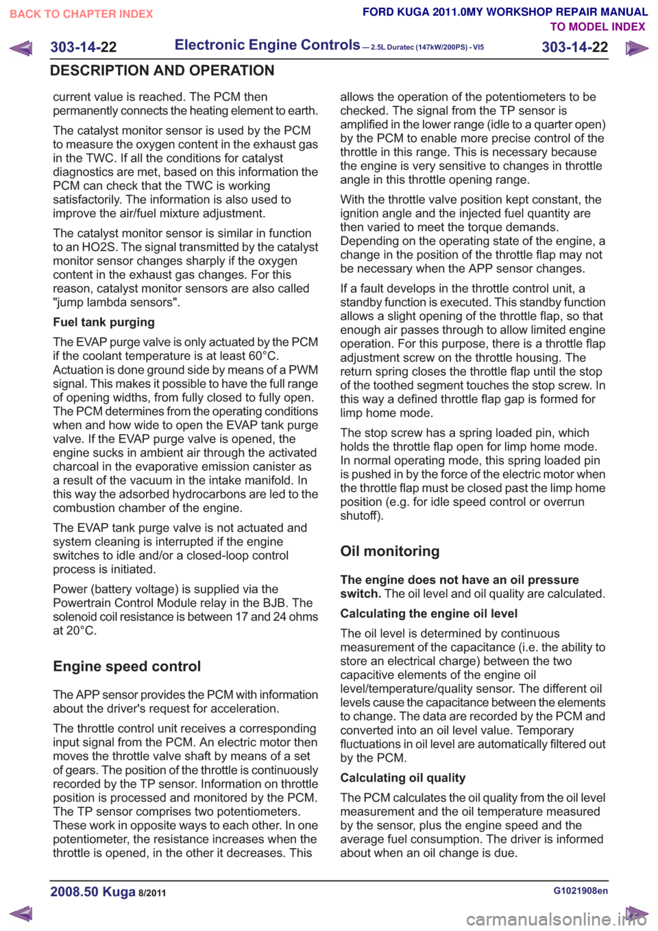
Oil monitoring
The engine does not have an oil pressure
switch.
The oil level and oil quality are calculated.
Calculating the engine oil level
The oil level is determined by continuous
measurement of the capacitance (i.e. the ability to
store an electrical charge) between the two
capacitive elements of the engine oil
level/temperature/quality sensor. The different oil
levels cause the capacitance between the elements
to change. The data are recorded by the PCM and
converted into an oil level value. Temporary
fluctuations in oil level are automatically filtered out
by the PCM.
Calculating oil quality
The PCM calculates the oil quality from the oil level
measurement and the oil temperature measured
by the sensor, plus the engine speed and the
average fuel consumption. The driver is informed
about when an oil change is due.
G1021908en2008.50 Kuga8/2011
303-14- 22
Electronic Engine Controls— 2.5L Duratec (147kW/200PS) - VI5303-14-
22
DESCRIPTION AND OPERATION
TO MODEL INDEX
BACK TO CHAPTER INDEX
FORD KUGA 2011.0MY WORKSHOP REPAIR MANUAL