Index FORD KUGA 2011 1.G Workshop Manual
[x] Cancel search | Manufacturer: FORD, Model Year: 2011, Model line: KUGA, Model: FORD KUGA 2011 1.GPages: 2057
Page 2043 of 2057
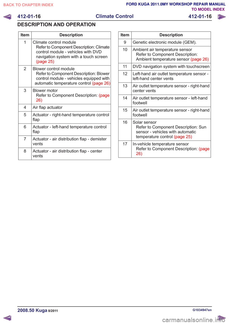
Description
Item
Climate control moduleRefer to Component Description: Climate
control module - vehicles with DVD
navigation system with a touch screen
(page25)
1
Blower control moduleRefer to Component Description: Blower
control module - vehicles equipped with
automatictemperaturecontrol(page26)
2
Blower motorRefertoComponentDescription:(page
26)
3
Air flap actuator
4
Actuator - right-hand temperature control
flap
5
Actuator - left-hand temperature control
flap
6
Actuator - air distribution flap - demister
vents
7
Actuator - air distribution flap - center
vents
8Description
Item
Genetic electronic module (GEM).
9
Ambient air temperature sensorRefer to Component Description:
Ambienttemperaturesensor(page26)
10
DVD navigation system with touchscreen
11
Left-hand air outlet temperature sensor -
left-hand center vents
12
Air outlet temperature sensor - right-hand
center vents
13
Air outlet temperature sensor - left-hand
footwell
14
Air outlet temperature sensor - right-hand
footwell
15
Solar sensorRefer to Component Description: Sun
sensor - vehicles with automatic
temperaturecontrol(page25)
16
In-vehicle temperature sensorRefertoComponentDescription:(page
26)
17
G1034947en2008.50 Kuga8/2011
412-01-
16
Climate Control
412-01- 16
DESCRIPTION AND OPERATION
TO MODEL INDEX
BACK TO CHAPTER INDEX
FORD KUGA 2011.0MY WORKSHOP REPAIR MANUAL
Page 2044 of 2057
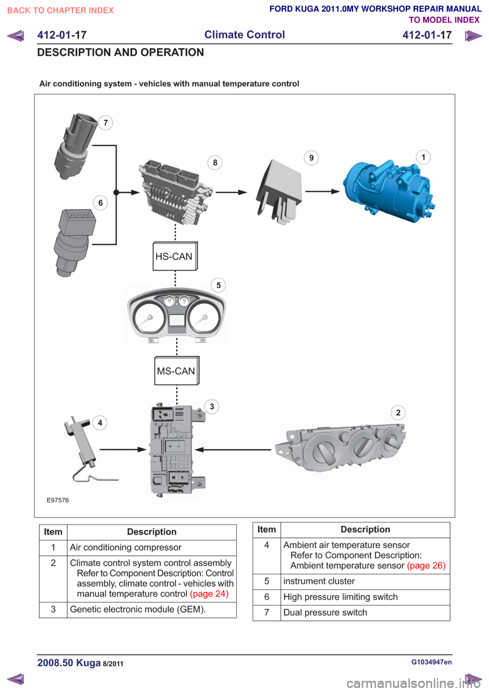
Air conditioning system - vehicles with manual temperature control
18
6
7
3
9
2
5
4
E97576
HS-CAN
MS-CAN
Description
Item
Air conditioning compressor
1
Climate control system control assemblyRefer to Component Description: Control
assembly, climate control - vehicles with
manualtemperaturecontrol(page24)
2
Genetic electronic module (GEM).
3Description
Item
Ambient air temperature sensorRefer to Component Description:
Ambienttemperaturesensor(page26)
4
instrument cluster
5
High pressure limiting switch
6
Dual pressure switch
7
G1034947en2008.50 Kuga8/2011
412-01- 17
Climate Control
412-01- 17
DESCRIPTION AND OPERATION
TO MODEL INDEX
BACK TO CHAPTER INDEX
FORD KUGA 2011.0MY WORKSHOP REPAIR MANUAL
Page 2045 of 2057
Description
Item
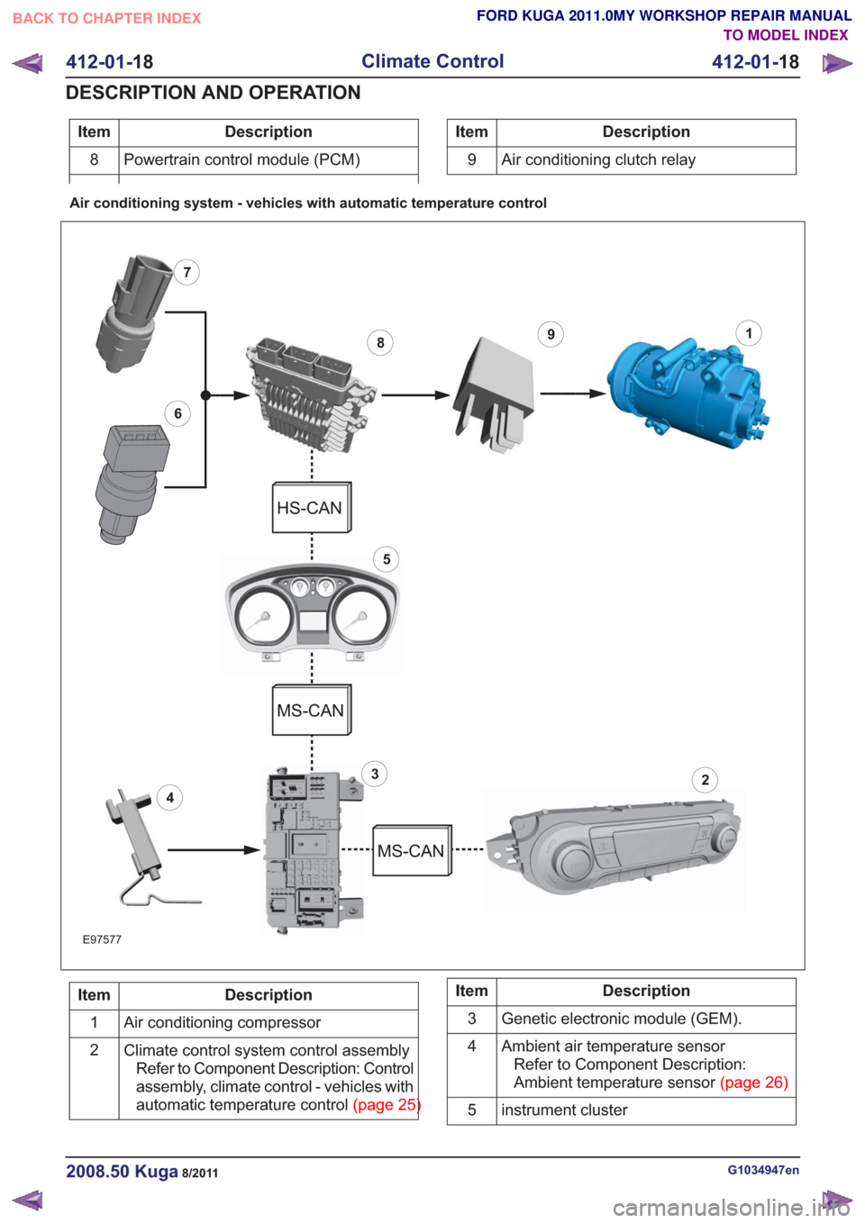
Powertrain control module (PCM)
8Description
Item
9 Air conditioning clutch relay
Air conditioning system - vehicles with automatic temperature control
18
6
7
3
9
5
2
4
E97577
HS-CAN
MS-CAN
MS-CAN
Description
Item
Air conditioning compressor
1
Climate control system control assemblyRefer to Component Description: Control
assembly, climate control - vehicles with
automatictemperaturecontrol(page25)
2Description
Item
Genetic electronic module (GEM).
3
Ambient air temperature sensorRefer to Component Description:
Ambienttemperaturesensor(page26)
4
instrument cluster
5
G1034947en2008.50 Kuga8/2011
412-01- 18
Climate Control
412-01- 18
DESCRIPTION AND OPERATION
TO MODEL INDEX
BACK TO CHAPTER INDEX
FORD KUGA 2011.0MY WORKSHOP REPAIR MANUAL
Page 2046 of 2057
Description
Item
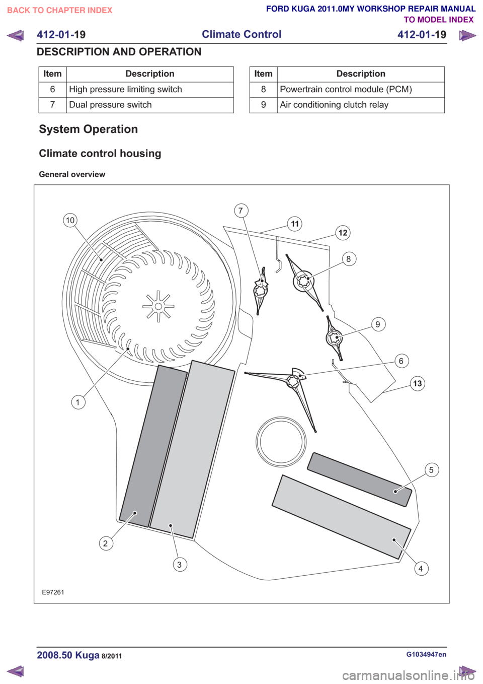
High pressure limiting switch
6
Dual pressure switch
7Description
Item
Powertrain control module (PCM)
8
Air conditioning clutch relay
9
System Operation
Climate control housing
General overview
13
12
11
8
7
9
6
4
5
2
3
E97261
1
10
G1034947en2008.50 Kuga8/2011
412-01- 19
Climate Control
412-01- 19
DESCRIPTION AND OPERATION
TO MODEL INDEX
BACK TO CHAPTER INDEX
FORD KUGA 2011.0MY WORKSHOP REPAIR MANUAL
Page 2047 of 2057
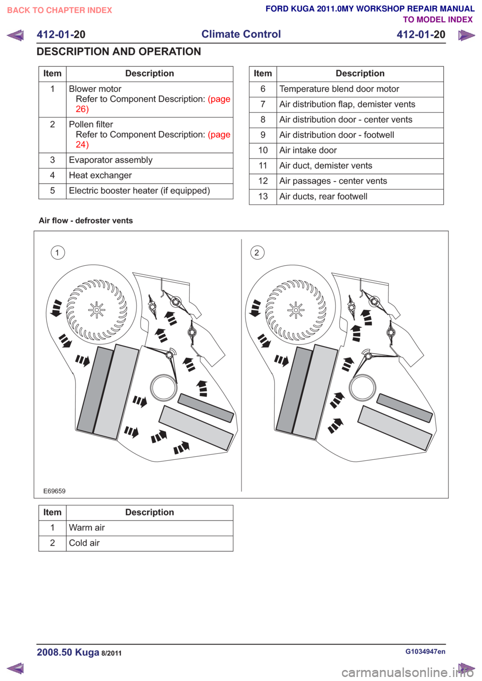
Description
Item
Blower motorRefertoComponentDescription:(page
26)
1
Pollen filterRefertoComponentDescription:(page
24)
2
Evaporator assembly
3
Heat exchanger
4
Electric booster heater (if equipped)
5Description
Item
Temperature blend door motor
6
Air distribution flap, demister vents
7
Air distribution door - center vents
8
Air distribution door - footwell
9
Air intake door
10
Air duct, demister vents
11
Air passages - center vents
12
Air ducts, rear footwell
13
Air flow - defroster vents
12
E69659
Description
Item
Warm air
1
Cold air
2
G1034947en2008.50 Kuga8/2011
412-01- 20
Climate Control
412-01- 20
DESCRIPTION AND OPERATION
TO MODEL INDEX
BACK TO CHAPTER INDEX
FORD KUGA 2011.0MY WORKSHOP REPAIR MANUAL
Page 2048 of 2057
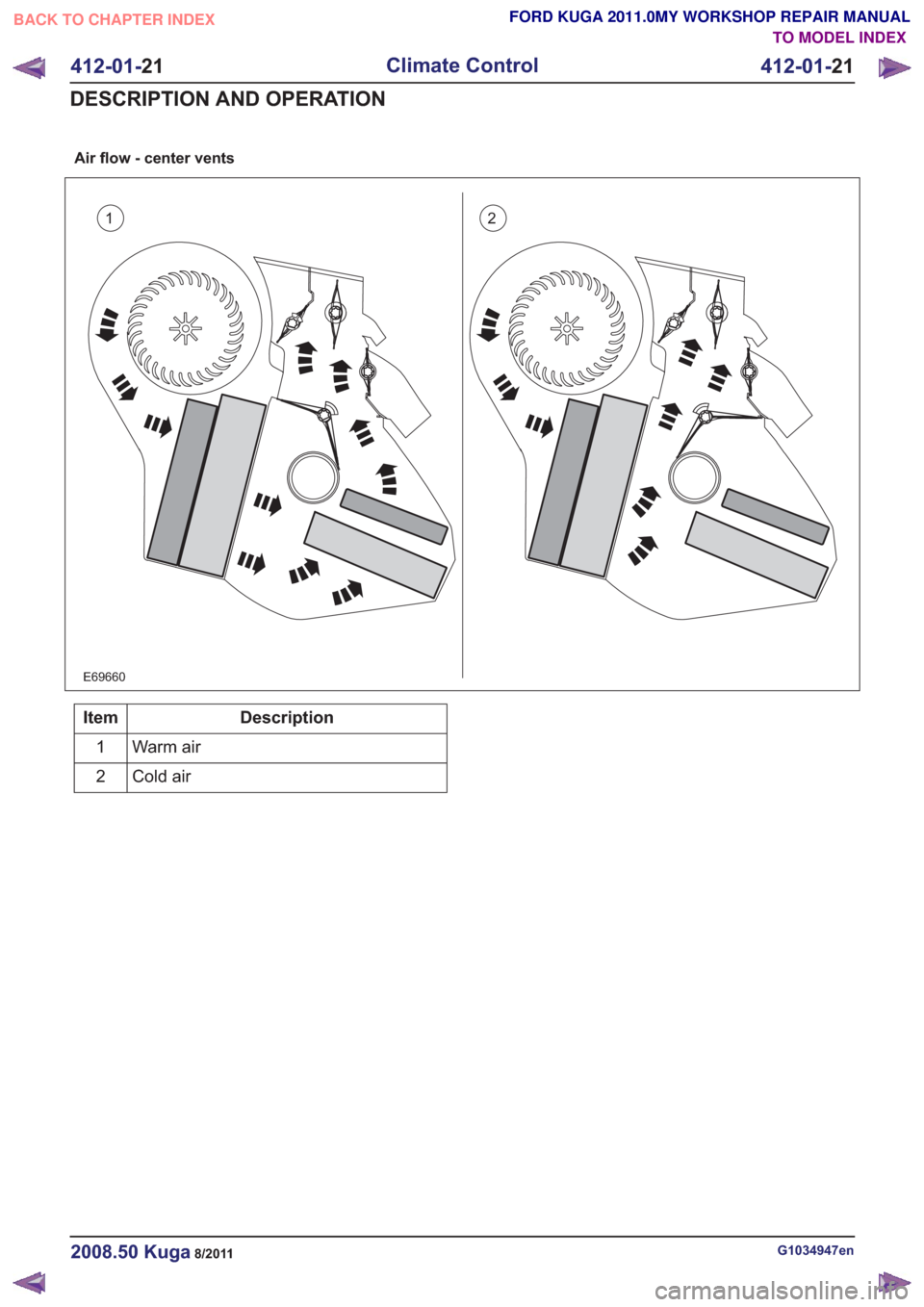
Air flow - center vents
12
E69660
Description
Item
Warm air
1
Cold air
2
G1034947en2008.50 Kuga8/2011
412-01- 21
Climate Control
412-01- 21
DESCRIPTION AND OPERATION
TO MODEL INDEX
BACK TO CHAPTER INDEX
FORD KUGA 2011.0MY WORKSHOP REPAIR MANUAL
Page 2049 of 2057
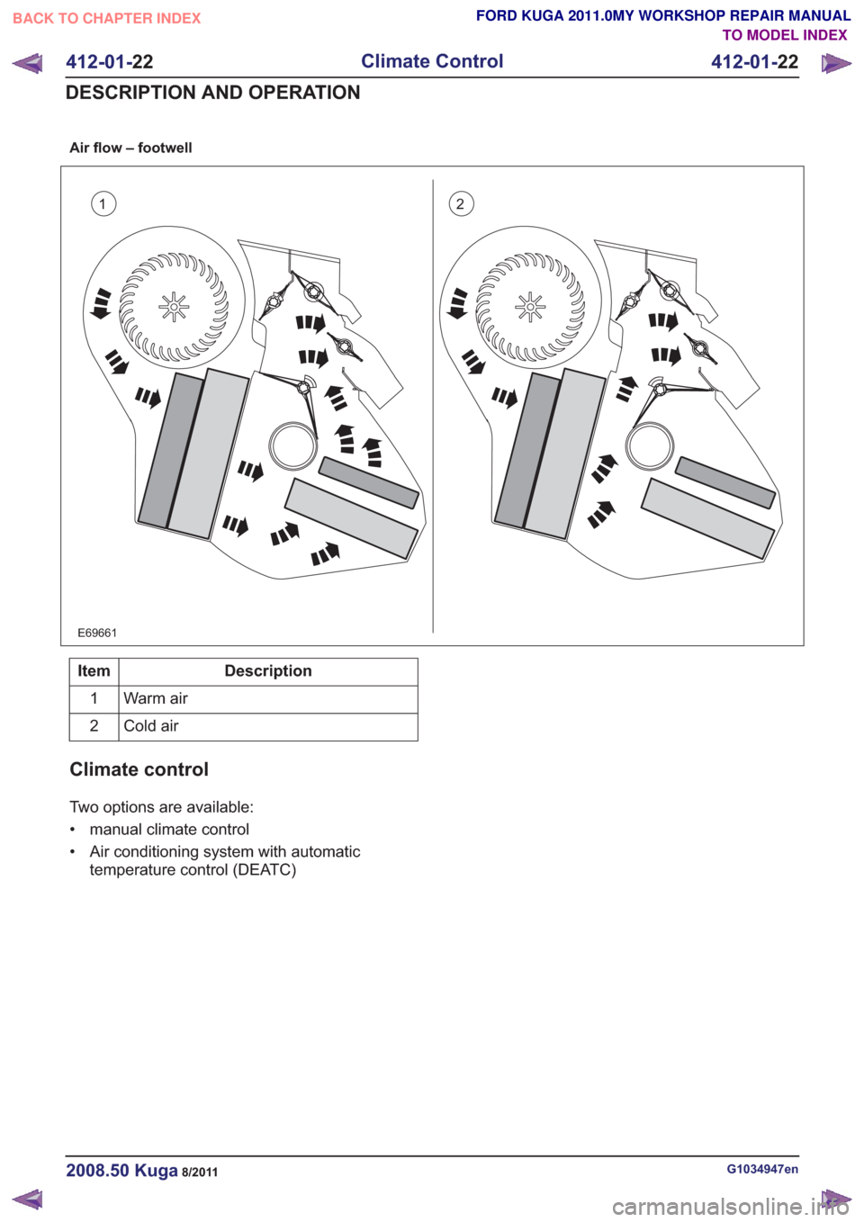
Air flow – footwell
12
E69661
Description
Item
Warm air
1
Cold air
2
Climate control
Two options are available:
• manual climate control
• Air conditioning system with automatic
temperature control (DEATC)
G1034947en2008.50 Kuga8/2011
412-01- 22
Climate Control
412-01- 22
DESCRIPTION AND OPERATION
TO MODEL INDEX
BACK TO CHAPTER INDEX
FORD KUGA 2011.0MY WORKSHOP REPAIR MANUAL
Page 2050 of 2057
1
2
3
5
4
67
8
9
10
11
E100819
Description
Item
Condenser
1
Air conditioning compressor
2
Suction accumulator
3
Evaporator assembly
4
Blower motor
5Description
Item
Evaporator Core Orifice Tube
6
Cooling fans.
7
High - pressure (liquid and warm)
8
Low - pressure (liquid and cool)
9
Low pressure (gaseous and cold)
10
High pressure (gaseous and hot)
11
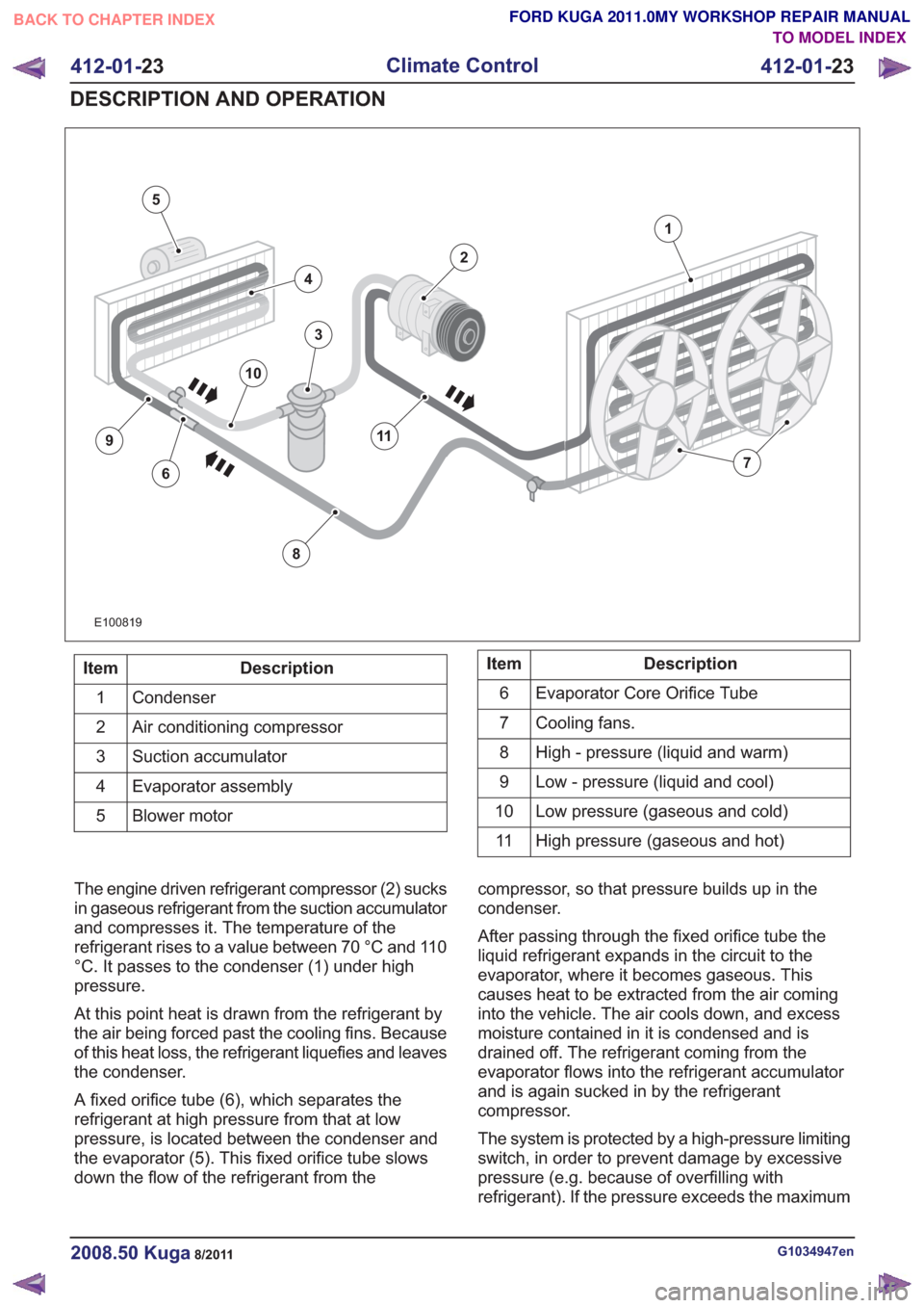
The engine driven refrigerant compressor (2) sucks
in gaseous refrigerant from the suction accumulator
and compresses it. The temperature of the
refrigerant rises to a value between 70 °C and 110
°C. It passes to the condenser (1) under high
pressure.
At this point heat is drawn from the refrigerant by
the air being forced past the cooling fins. Because
of this heat loss, the refrigerant liquefies and leaves
the condenser.
A fixed orifice tube (6), which separates the
refrigerant at high pressure from that at low
pressure, is located between the condenser and
the evaporator (5). This fixed orifice tube slows
down the flow of the refrigerant from the compressor, so that pressure builds up in the
condenser.
After passing through the fixed orifice tube the
liquid refrigerant expands in the circuit to the
evaporator, where it becomes gaseous. This
causes heat to be extracted from the air coming
into the vehicle. The air cools down, and excess
moisture contained in it is condensed and is
drained off. The refrigerant coming from the
evaporator flows into the refrigerant accumulator
and is again sucked in by the refrigerant
compressor.
The system is protected by a high-pressure limiting
switch, in order to prevent damage by excessive
pressure (e.g. because of overfilling with
refrigerant). If the pressure exceeds the maximum
G1034947en2008.50 Kuga8/2011
412-01-
23
Climate Control
412-01- 23
DESCRIPTION AND OPERATION
TO MODEL INDEX
BACK TO CHAPTER INDEX
FORD KUGA 2011.0MY WORKSHOP REPAIR MANUAL
Page 2051 of 2057
permitted, the high-pressure switch turns off the
refrigerant compressor.
The compressor on-off cycle is controlled by the
dual pressure switch depending on the pressure
in the refrigerant accumulator. The dual pressure
switch turns the refrigerant compressor off
permanently if the pressure falls below a permitted
value (e.g. if there is a leak).
Component Description
Air conditioning compressor
E100826
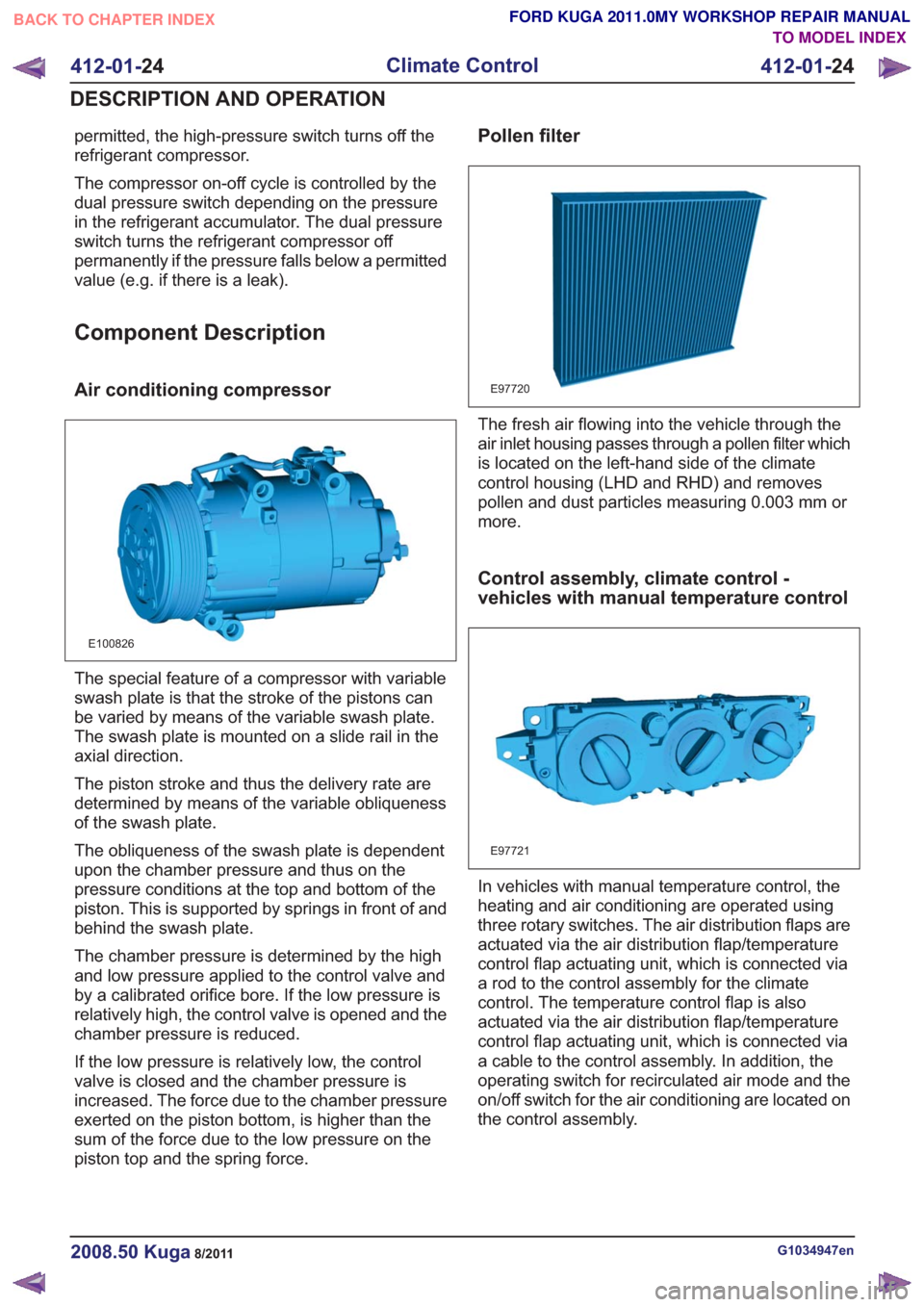
The special feature of a compressor with variable
swash plate is that the stroke of the pistons can
be varied by means of the variable swash plate.
The swash plate is mounted on a slide rail in the
axial direction.
The piston stroke and thus the delivery rate are
determined by means of the variable obliqueness
of the swash plate.
The obliqueness of the swash plate is dependent
upon the chamber pressure and thus on the
pressure conditions at the top and bottom of the
piston. This is supported by springs in front of and
behind the swash plate.
The chamber pressure is determined by the high
and low pressure applied to the control valve and
by a calibrated orifice bore. If the low pressure is
relatively high, the control valve is opened and the
chamber pressure is reduced.
If the low pressure is relatively low, the control
valve is closed and the chamber pressure is
increased. The force due to the chamber pressure
exerted on the piston bottom, is higher than the
sum of the force due to the low pressure on the
piston top and the spring force.
Pollen filter
E97720
The fresh air flowing into the vehicle through the
air inlet housing passes through a pollen filter which
is located on the left-hand side of the climate
control housing (LHD and RHD) and removes
pollen and dust particles measuring 0.003 mm or
more.
Control assembly, climate control -
vehicles with manual temperature control
E97721
In vehicles with manual temperature control, the
heating and air conditioning are operated using
three rotary switches. The air distribution flaps are
actuated via the air distribution flap/temperature
control flap actuating unit, which is connected via
a rod to the control assembly for the climate
control. The temperature control flap is also
actuated via the air distribution flap/temperature
control flap actuating unit, which is connected via
a cable to the control assembly. In addition, the
operating switch for recirculated air mode and the
on/off switch for the air conditioning are located on
the control assembly.
G1034947en2008.50 Kuga8/2011
412-01-24
Climate Control
412-01- 24
DESCRIPTION AND OPERATION
TO MODEL INDEX
BACK TO CHAPTER INDEX
FORD KUGA 2011.0MY WORKSHOP REPAIR MANUAL
Page 2052 of 2057
Control assembly, climate control -
vehicles with automatic temperature
control
E97722
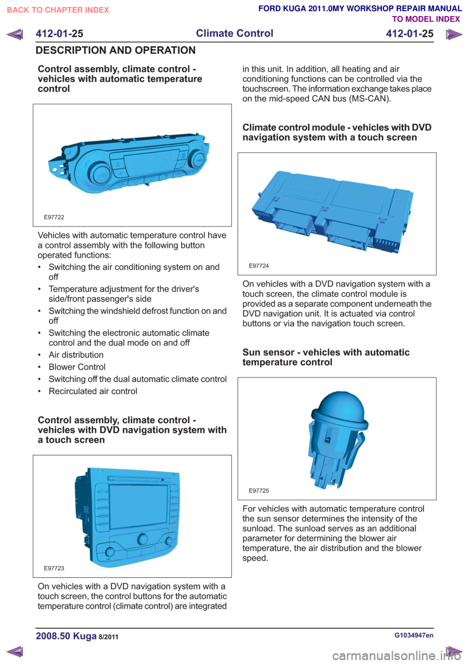
Vehicles with automatic temperature control have
a control assembly with the following button
operated functions:
• Switching the air conditioning system on andoff
• Temperature adjustment for the driver's side/front passenger's side
• Switching the windshield defrost function on and off
• Switching the electronic automatic climate control and the dual mode on and off
• Air distribution
• Blower Control
• Switching off the dual automatic climate control
• Recirculated air control
Control assembly, climate control -
vehicles with DVD navigation system with
a touch screen
E97723
On vehicles with a DVD navigation system with a
touch screen, the control buttons for the automatic
temperature control (climate control) are integrated in this unit. In addition, all heating and air
conditioning functions can be controlled via the
touchscreen. The information exchange takes place
on the mid-speed CAN bus (MS-CAN).
Climate control module - vehicles with DVD
navigation system with a touch screen
E97724
On vehicles with a DVD navigation system with a
touch screen, the climate control module is
provided as a separate component underneath the
DVD navigation unit. It is actuated via control
buttons or via the navigation touch screen.
Sun sensor - vehicles with automatic
temperature control
E97725
For vehicles with automatic temperature control
the sun sensor determines the intensity of the
sunload. The sunload serves as an additional
parameter for determining the blower air
temperature, the air distribution and the blower
speed.
G1034947en2008.50 Kuga8/2011
412-01-
25
Climate Control
412-01- 25
DESCRIPTION AND OPERATION
TO MODEL INDEX
BACK TO CHAPTER INDEX
FORD KUGA 2011.0MY WORKSHOP REPAIR MANUAL