Engine cooling FORD KUGA 2011 1.G User Guide
[x] Cancel search | Manufacturer: FORD, Model Year: 2011, Model line: KUGA, Model: FORD KUGA 2011 1.GPages: 2057
Page 1583 of 2057
Cylinder Head(21 163 0)
General EquipmentFluid Container
Tire Lever
Materials
Specification
Name
WSS-M2C913-C
Engine Oil - 5W-30
SA-M1C9107-A / YS5J-
M1C9107-AA
Grease KS-PS
Removal
NOTE:
Removal steps in this procedure may
contain installation details.
1. Refer to: Cooling System Draining and Vacuum
Filling (303-03 Engine Cooling, General
Procedures).
2. Refer to: Fuel System Pressure Release
(310-00 Fuel System - General Information,
General Procedures).
3. Refer to: Battery Disconnect and Connect
(414-01 Battery, Mounting and Cables,
General Procedures).
4. Refer to: Air Cleaner (303-12 Intake Air
Distribution and Filtering - 2.5L Duratec
(147kW/200PS) - VI5, Removal and
Installation).
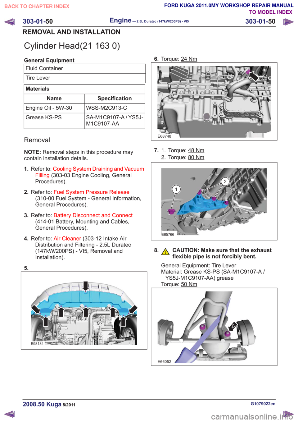
5.
E98184
6. Torque: 24Nm
E68748
7. Torque: 48Nm1.
2. Torque: 80
Nm
E65766
1
2
8. CAUTION: Make sure that the exhaust
flexible pipe is not forcibly bent.
General Equipment: Tire Lever
Material: Grease KS-PS (SA-M1C9107-A /YS5J-M1C9107-AA) grease
Torque: 50
Nm
E66052
x2
G1079022en2008.50 Kuga8/2011
303-01- 50
Engine— 2.5L Duratec (147kW/200PS) - VI5303-01-
50
REMOVAL AND INSTALLATION
TO MODEL INDEX
BACK TO CHAPTER INDEX
FORD KUGA 2011.0MY WORKSHOP REPAIR MANUAL
Page 1591 of 2057
Oil Cooler(21 764 0)
General EquipmentFluid Container
Hose Clamp(s)
Materials
Specification
Name
WSS-M2C913-C
Engine Oil - 5W-30
Removal
NOTE: Removal steps in the procedure may
contain installation details.
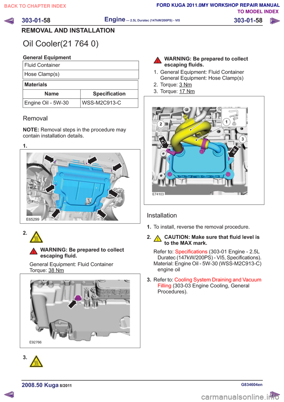
1.
E65299
2.
WARNING: Be prepared to collect
escaping fluid.
General Equipment: Fluid Container
Torque: 38
Nm
E92766
3.
WARNING: Be prepared to collect
escaping fluids.
1. General Equipment: Fluid Container General Equipment: Hose Clamp(s)
2. Torque: 3
Nm
3. Torque: 17Nm
E74103
x4
x2
2
3
1
Installation
1. To install, reverse the removal procedure.
2. CAUTION: Make sure that fluid level is to the MAX mark.
Refer to: Specifications (303-01 Engine - 2.5L
Duratec (147kW/200PS) - VI5, Specifications).
Material: Engine Oil - 5W-30 (WSS-M2C913-C) engine oil
3. Refer to: Cooling System Draining and Vacuum
Filling (303-03 Engine Cooling, General
Procedures).
G834604en2008.50 Kuga8/2011
303-01- 58
Engine— 2.5L Duratec (147kW/200PS) - VI5303-01-
58
REMOVAL AND INSTALLATION
TO MODEL INDEX
BACK TO CHAPTER INDEX
FORD KUGA 2011.0MY WORKSHOP REPAIR MANUAL
Page 1598 of 2057
25.Refer to: Lifting(100-02 Jacking and Lifting,
Description and Operation).
26. Refer to: Cooling System Draining and Vacuum
Filling (303-03 Engine Cooling, General
Procedures).
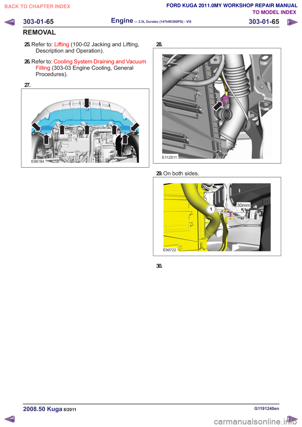
27.
E98184
28.
E112511
29. On both sides.
E99722
30mm1
30.
G1191240en2008.50 Kuga8/2011
303-01- 65
Engine— 2.5L Duratec (147kW/200PS) - VI5303-01-
65
REMOVAL
TO MODEL INDEX
BACK TO CHAPTER INDEX
FORD KUGA 2011.0MY WORKSHOP REPAIR MANUAL
Page 1671 of 2057
67.Install the following items:
1. Refer to: Battery(414-01 Battery, Mounting
and Cables, Removal and Installation).
2. Refer to: Cowl Panel Grille (501-02 Front
End Body Panels, Removal and
Installation).
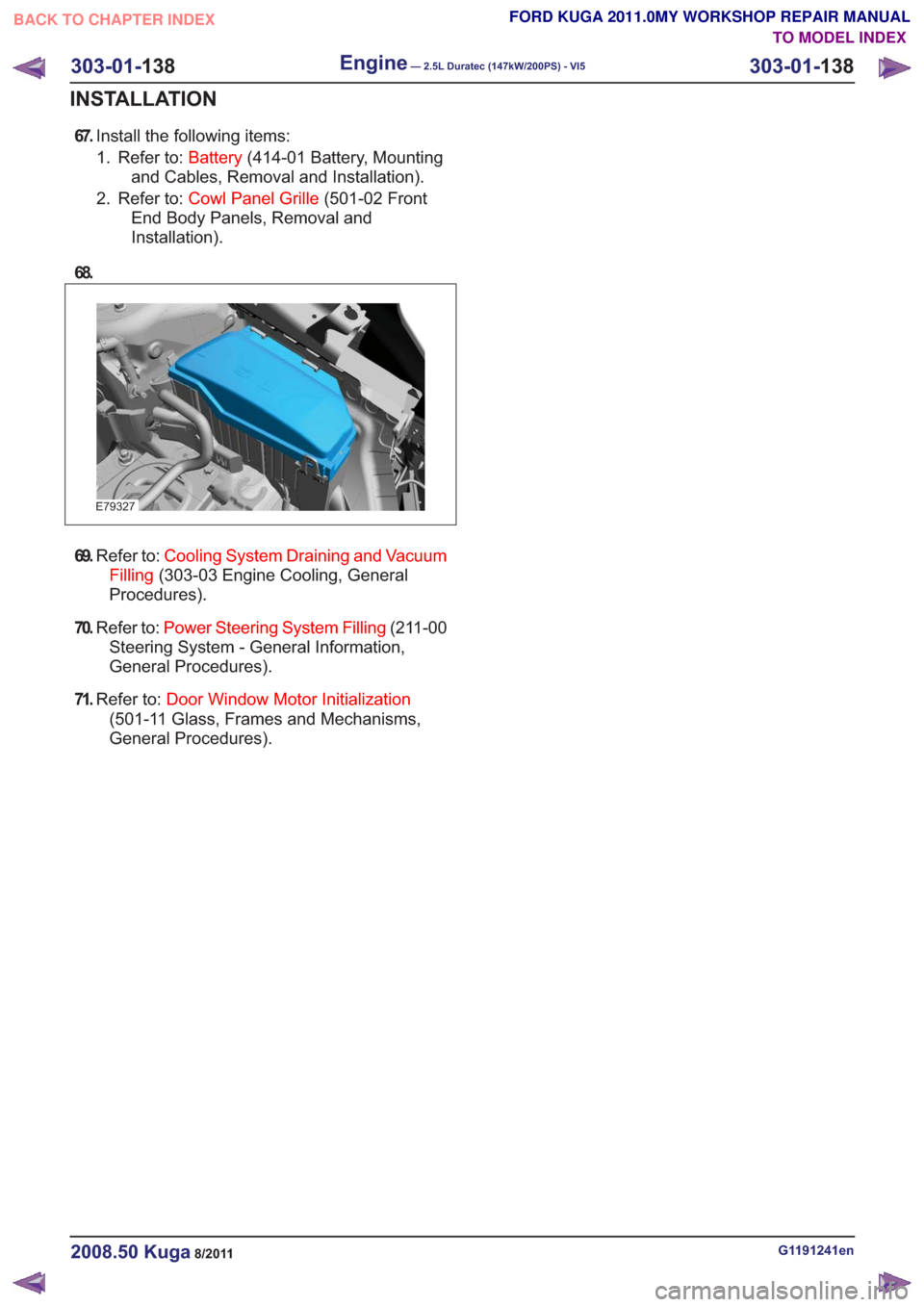
68.
E79327
69. Refer to: Cooling System Draining and Vacuum
Filling (303-03 Engine Cooling, General
Procedures).
70. Refer to: Power Steering System Filling (211-00
Steering System - General Information,
General Procedures).
71. Refer to: Door Window Motor Initialization
(501-11 Glass, Frames and Mechanisms,
General Procedures).
G1191241en2008.50 Kuga8/2011
303-01- 138
Engine— 2.5L Duratec (147kW/200PS) - VI5303-01-
138
INSTALLATION
TO MODEL INDEX
BACK TO CHAPTER INDEX
FORD KUGA 2011.0MY WORKSHOP REPAIR MANUAL
Page 1672 of 2057
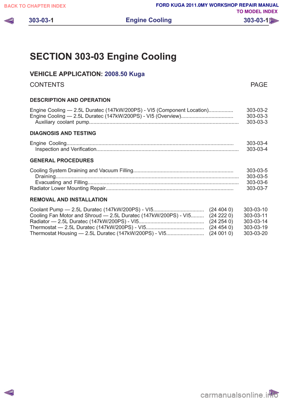
SECTION 303-03 Engine Cooling
VEHICLE APPLICATION:2008.50 Kuga
PA G E
CONTENTS
DESCRIPTION AND OPERATION
303-03-2
Engine Cooling — 2.5L Duratec (147kW/200PS) - VI5 (Component Location) .................
303-03-3
Engine Cooling — 2.5L Duratec (147kW/200PS) - VI5 (Overview) ....................................
303-03-3
Auxiliary coolant pump ........................................................................\
...............................
DIAGNOSIS AND TESTING 303-03-4
Engine Cooling ........................................................................\
...........................................
303-03-4
Inspection and Verification ........................................................................\
..........................
GENERAL PROCEDURES 303-03-5
Cooling System Draining and Vacuum Filling .....................................................................
303-03-5
Draining ........................................................................\
......................................................
303-03-6
Evacuating and Filling ........................................................................\
................................
303-03-7
Radiator Lower Mounting Repair ........................................................................\
................
REMOVAL AND INSTALLATION 303-03-10
(24 404 0)
Coolant Pump — 2.5L Duratec (147kW/200PS) - VI5 ...................................
303-03-11
(24 222 0)
Cooling Fan Motor and Shroud — 2.5L Duratec (147kW/200PS) - VI5 .........
303-03-14
(24 254 0)
Radiator — 2.5L Duratec (147kW/200PS) - VI5 .............................................
303-03-19
(24 454 0)
Thermostat — 2.5L Duratec (147kW/200PS) - VI5 ........................................
303-03-20
(24 001 0)
Thermostat Housing — 2.5L Duratec (147kW/200PS) - VI5 ..........................
303-03-1
Engine Cooling
303-03- 1
.
TO MODEL INDEX
BACK TO CHAPTER INDEX
FORD KUGA 2011.0MY WORKSHOP REPAIR MANUAL
Page 1673 of 2057
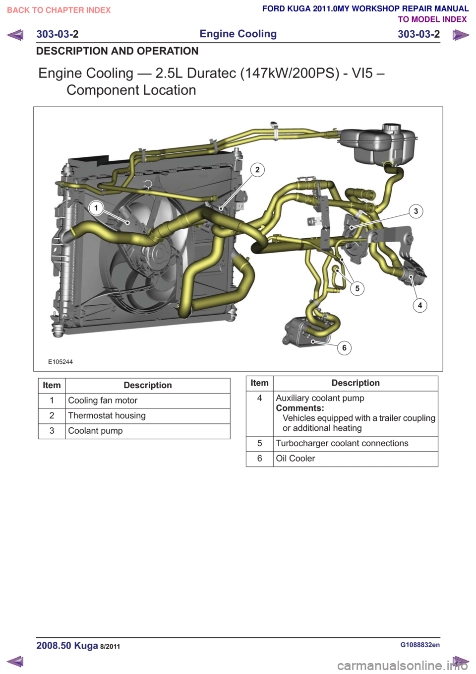
Engine Cooling — 2.5L Duratec (147kW/200PS) - VI5 –Component Location
E105244
1
2
3
4
5
6
Description
Item
Cooling fan motor
1
Thermostat housing
2
Coolant pump
3Description
Item
Auxiliary coolant pump
Comments:Vehicles equipped with a trailer coupling
or additional heating
4
Turbocharger coolant connections
5
Oil Cooler
6
G1088832en2008.50 Kuga8/2011
303-03- 2
Engine Cooling
303-03- 2
DESCRIPTION AND OPERATION
TO MODEL INDEX
BACK TO CHAPTER INDEX
FORD KUGA 2011.0MY WORKSHOP REPAIR MANUAL
Page 1674 of 2057
Engine Cooling — 2.5L Duratec (147kW/200PS) - VI5 – Overview
Auxiliary coolant pump
An electrically operated auxiliary coolant pump is
installed on vehicles with a trailer coupling and/or
additional heating. The auxiliary coolant pump
ensures that the coolant is circulated when the
coolant pump (which is driven by the engine) is not
running.
The additional heating uses the auxiliary coolant
pump to circulate hot coolant through the heat
exchanger and the engine.
On vehicles with a trailer coupling the auxiliary
coolant pump is switched on for 6 minutes by the
PCM (powertrain control module) if the coolant
temperature exceeds 106°C when the engine is
switched off. This prevents the coolant circuit from
overheating. This could happen particularly if the
engine is switched off after towing a heavy trailer
up a steep hill before there has been sufficient time
for cooling.
G1088220en2008.50 Kuga8/2011
303-03-3
Engine Cooling
303-03- 3
DESCRIPTION AND OPERATION
TO MODEL INDEX
BACK TO CHAPTER INDEX
FORD KUGA 2011.0MY WORKSHOP REPAIR MANUAL
Page 1675 of 2057
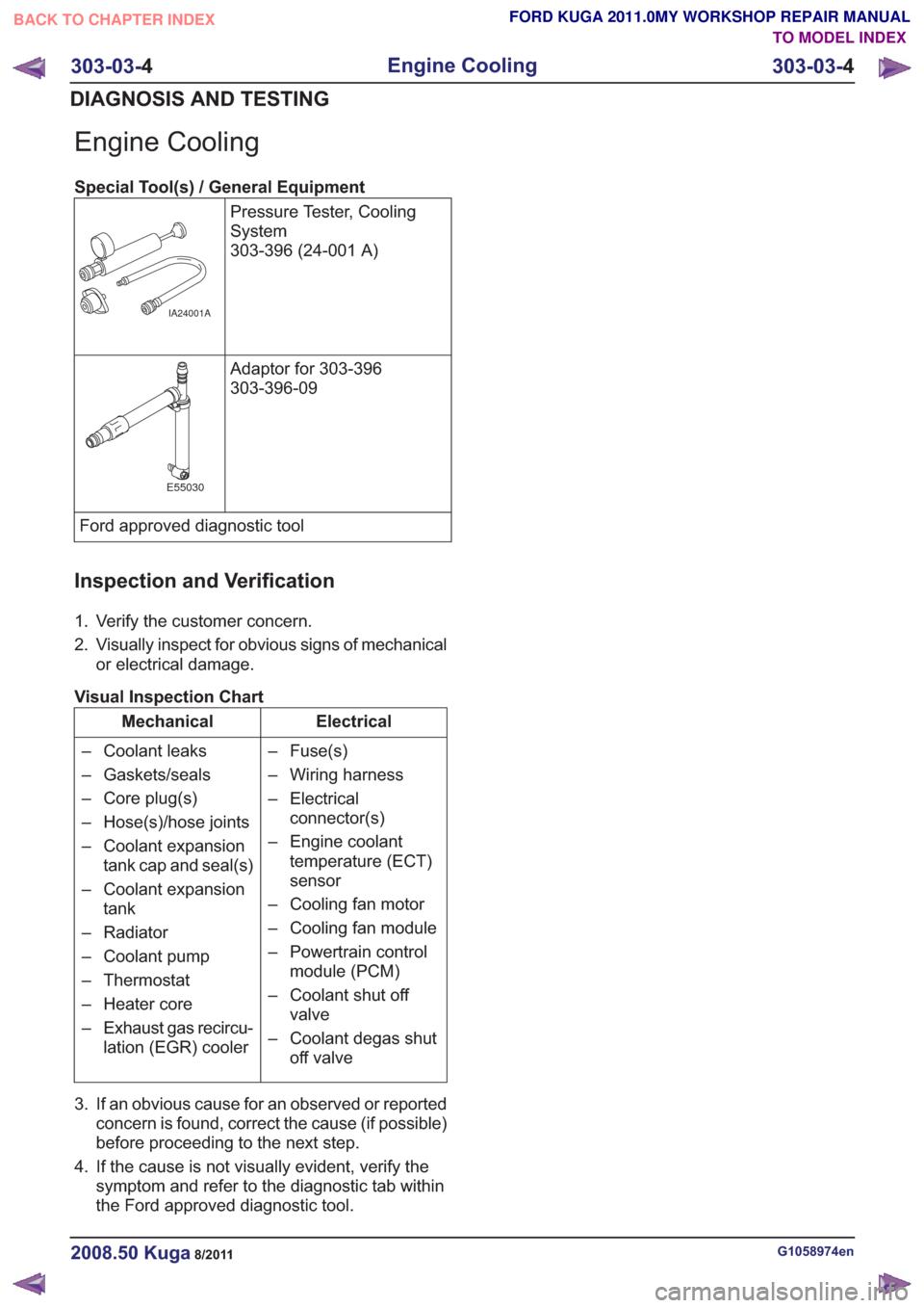
Engine Cooling
Special Tool(s) / General EquipmentPressure Tester, Cooling
System
303-396 (24-001 A)
IA24001A
Adaptor for 303-396
303-396-09
E55030
Ford approved diagnostic tool
Inspection and Verification
1. Verify the customer concern.
2. Visually inspect for obvious signs of mechanicalor electrical damage.
Visual Inspection Chart
Electrical
Mechanical
– Fuse(s)
– Wiring harness
– Electricalconnector(s)
– Engine coolant temperature (ECT)
sensor
– Cooling fan motor
– Cooling fan module
– Powertrain control module (PCM)
– Coolant shut off valve
– Coolant degas shut off valve
– Coolant leaks
– Gaskets/seals
– Core plug(s)
– Hose(s)/hose joints
– Coolant expansion
tank cap and seal(s)
– Coolant expansion tank
– Radiator
– Coolant pump
– Thermostat
– Heater core
– Exhaust gas recircu- lation (EGR) cooler
3. If an obvious cause for an observed or reported concern is found, correct the cause (if possible)
before proceeding to the next step.
4. If the cause is not visually evident, verify the symptom and refer to the diagnostic tab within
the Ford approved diagnostic tool.
G1058974en2008.50 Kuga8/2011
303-03- 4
Engine Cooling
303-03- 4
DIAGNOSIS AND TESTING
TO MODEL INDEX
BACK TO CHAPTER INDEX
FORD KUGA 2011.0MY WORKSHOP REPAIR MANUAL
Page 1676 of 2057
Cooling System Draining and Vacuum Filling
General EquipmentCooling System Vacuum Tester and Refiller
Fluid Container
Materials
Specification
Name
WSS-M97B44-D / 4U7J-
19544-AA2A
Antifreeze Super Plus
Premium
Draining
WARNING: When releasing the cooling
system pressure, cover the coolant
expansion tank cap with a thick cloth.
NOTE: Always follow the manufacturer's
instructions when handling the equipment.
1. Refer to: Engine Cooling System Health and
Safety Precautions (100-00 General
Information, Description and Operation).
2.
Release the cooling system pressure by slowly
turning the coolant expansion tank cap between
2 and 3 turns.
E68577
3. Refer to: Lifting(100-02 Jacking and Lifting,
Description and Operation).
4.
E65299
5.
WARNING: Be prepared to collect
escaping fluid.
Use a suitable coolant hose to drain the coolant.
General Equipment: Fluid Container
Loosen: 4
turn(s)
E97501
6.
E97501
G1034816en2008.50 Kuga8/2011
303-03- 5
Engine Cooling
303-03- 5
GENERAL PROCEDURES
TO MODEL INDEX
BACK TO CHAPTER INDEX
FORD KUGA 2011.0MY WORKSHOP REPAIR MANUAL
Page 1677 of 2057
7.
E65299
Evacuating and Filling
1.If the cooling system was completely drained,
fill the fluid container with the full cooling
•
system fill capacity plus 0.5L of additional
coolant.
Material: Antifreeze Super Plus Premium(WSS-M97B44-D / 4U7J-19544-AA2A)
antifreeze
• If the cooling system was partially drained, fill the fluid container with the removed and
spilled amount of coolant plus 1.0L of
additional coolant. When in doubt always use
the full cooling system fill capacity plus 0.5L
of additional coolant.
Material: Antifreeze Super Plus Premium(WSS-M97B44-D / 4U7J-19544-AA2A)
antifreeze
2. General Equipment: Cooling System Vacuum
Tester and Refiller
•
3. Close the valve, install the coolant hose and
place it into the fluid container.
1.
2. Close the valve and connect the compressed
air hose.
E96739
1
2
4. Open the valve until the specificied vacuum
is achieved.
2.
E967406-10 bar
1
-0.85 bar
-0.95 bar2
5.
Open the valve until the coolant reservoir
fluid level is at the MAX mark.
•
• If no coolant is visible in the coolant
expansion tank, add 2.0L of coolant to the
fluid container and repeat the evacuating and
filling procedure.
E96741
6.
E68577
G1034816en2008.50 Kuga8/2011
303-03- 6
Engine Cooling
303-03- 6
GENERAL PROCEDURES
TO MODEL INDEX
BACK TO CHAPTER INDEX
FORD KUGA 2011.0MY WORKSHOP REPAIR MANUAL