Pipe FORD KUGA 2011 1.G User Guide
[x] Cancel search | Manufacturer: FORD, Model Year: 2011, Model line: KUGA, Model: FORD KUGA 2011 1.GPages: 2057
Page 1584 of 2057
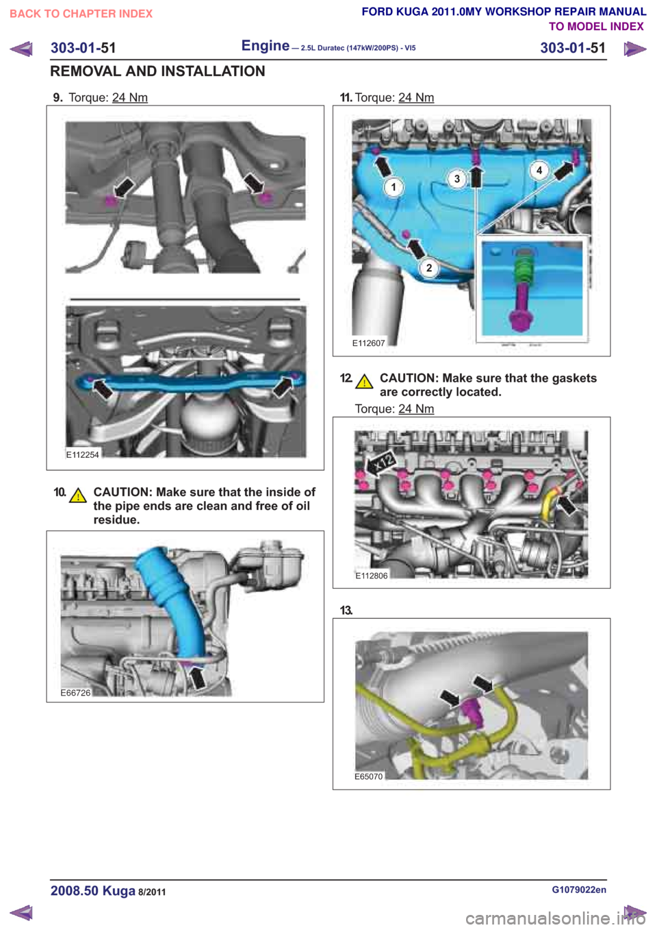
9.Torque: 24Nm
E112254
G1079022en2008.50 Kuga8/2011
303-01- 51
Engine— 2.5L Duratec (147kW/200PS) - VI5303-01-
51
REMOVAL AND INSTALLATION
FORD KUGA 2011.0MY WORKSHOP REPAIR MANUAL
TO MODEL INDEX
BACK TO CHAPTER INDEX
E66726
10. CAUTION: Make sure that the inside of the pipe ends are clean and free of oil
residue.
11 .Torque: 24Nm
E112607
1
2
34
12. CAUTION: Make sure that the gaskets
are correctly located.
E112806
13.
E65070
Torque: 24Nm
Page 1585 of 2057
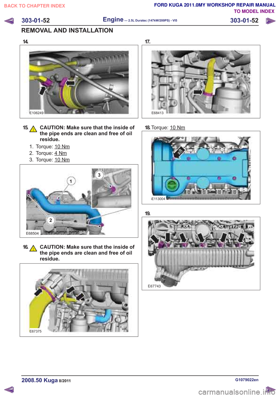
15. CAUTION: Make sure that the inside ofthe pipe ends are clean and free of oil
residue.
1. Torque: 10
E68504
16. CAUTION: Make sure that the inside ofthe pipe ends are clean and free of oil
residue.
E68413
18.Torque: 10Nm
E113004
x8
19.
G1079022en2008.50 Kuga8/2011
303-01- 52
Engine— 2.5L Duratec (147kW/200PS) - VI5303-01-
52
REMOVAL AND INSTALLATION
FORD KUGA 2011.0MY WORKSHOP REPAIR MANUAL
TO MODEL INDEX
BACK TO CHAPTER INDEX
E67743
14.
E106249
Nm
2. Torque: 4Nm
3. Torque: 10Nm
2
1
3
17.
E67375
Page 1602 of 2057
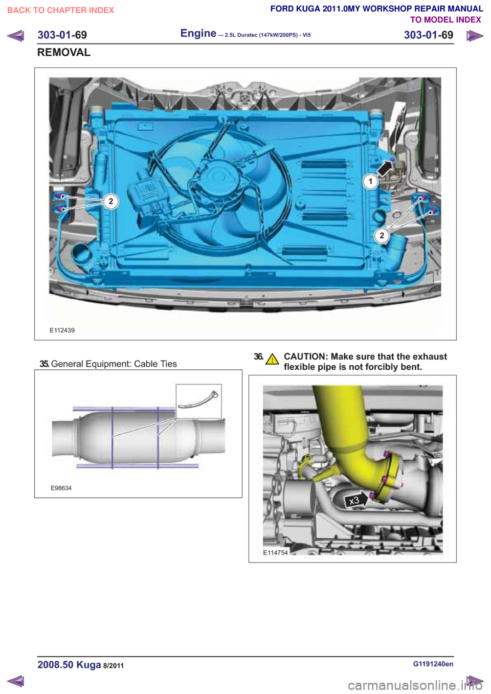
35.General Equipment: Cable Ties
E98634
36. CAUTION: Make sure that the exhaust
flexible pipe is not forcibly bent.
G1191240en2008.50 Kuga8/2011
303-01- 69
Engine— 2.5L Duratec (147kW/200PS) - VI5303-01-
69
REMOVAL
TO MODEL INDEX
BACK TO CHAPTER INDEX
FORD KUGA 2011.0MY WORKSHOP REPAIR MANUAL
E112439
1
2
2
x3
E114754
Page 1606 of 2057
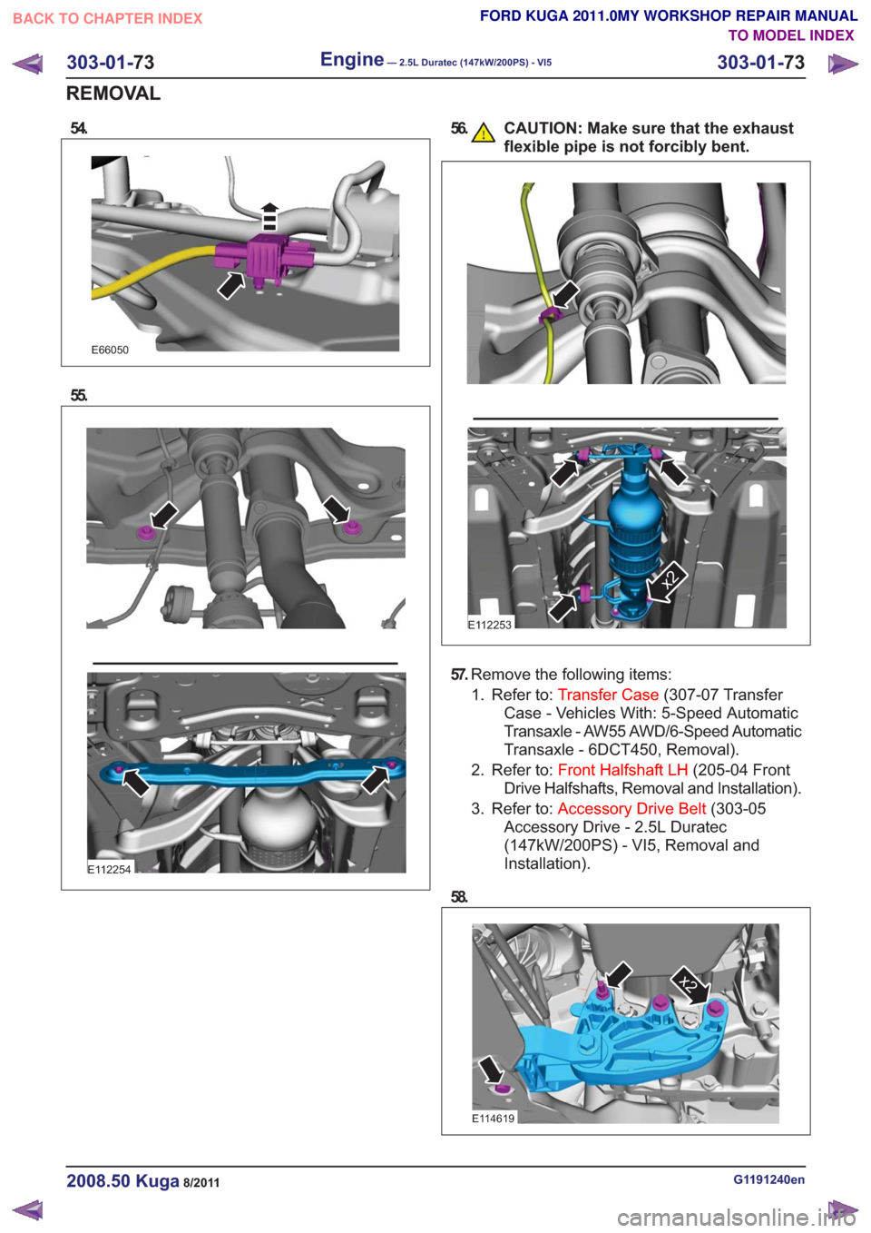
54.
E66050
55.
E112254
56. CAUTION: Make sure that the exhaustflexible pipe is not forcibly bent.
E112253
x2
57.Remove the following items:
1. Refer to: Transfer Case (307-07 Transfer
Case - Vehicles With: 5-Speed Automatic
Transaxle - AW55 AWD/6-Speed Automatic
Transaxle - 6DCT450, Removal).
2. Refer to: Front Halfshaft LH (205-04 Front
Drive Halfshafts, Removal and Installation).
3. Refer to: Accessory Drive Belt (303-05
Accessory Drive - 2.5L Duratec
(147kW/200PS) - VI5, Removal and
Installation).
58.
x2x2
E114619
G1191240en2008.50 Kuga8/2011
303-01- 73
Engine— 2.5L Duratec (147kW/200PS) - VI5303-01-
73
REMOVAL
TO MODEL INDEX
BACK TO CHAPTER INDEX
FORD KUGA 2011.0MY WORKSHOP REPAIR MANUAL
Page 1657 of 2057
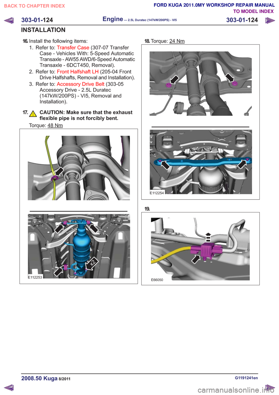
16.Install the following items:
1. Refer to: Transfer Case (307-07 Transfer
Case - Vehicles With: 5-Speed Automatic
Transaxle - AW55 AWD/6-Speed Automatic
Transaxle - 6DCT450, Removal).
2. Refer to: Front Halfshaft LH (205-04 Front
Drive Halfshafts, Removal and Installation).
3. Refer to: Accessory Drive Belt (303-05
Accessory Drive - 2.5L Duratec
(147kW/200PS) - VI5, Removal and
Installation).
17. CAUTION: Make sure that the exhaust flexible pipe is not forcibly bent.
Torque: 48Nm
E112253
x2
18.Torque: 24Nm
E112254
19.
E66050
G1191241en2008.50 Kuga8/2011
303-01- 124
Engine— 2.5L Duratec (147kW/200PS) - VI5303-01-
124
INSTALLATION
TO MODEL INDEX
BACK TO CHAPTER INDEX
FORD KUGA 2011.0MY WORKSHOP REPAIR MANUAL
Page 1658 of 2057
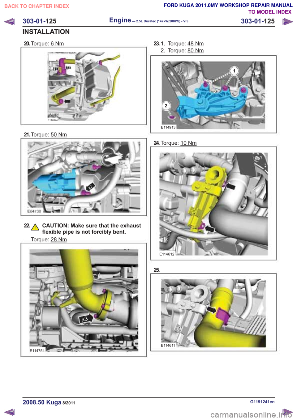
20.Torque: 6Nm
E114754
23. Torque: 48Nm1.
2. Torque: 80
303-01- 125
Engine— 2.5L Duratec (147kW/200PS) - VI5303-01-
125
INSTALLATION
TO MODEL INDEX
BACK TO CHAPTER INDEX
FORD KUGA 2011.0MY WORKSHOP REPAIR MANUAL
E114624
21.
Torque: 50
x2
22. CAUTION: Make sure that the exhaust
flexible pipe is not forcibly bent.
Torque: 28Nm
Nm
E114913
24.Torque: 10
E114612
25.
E114611
G1191241en2008.50 Kuga8/2011
Nm
1
2
Nm
x3
Page 1668 of 2057
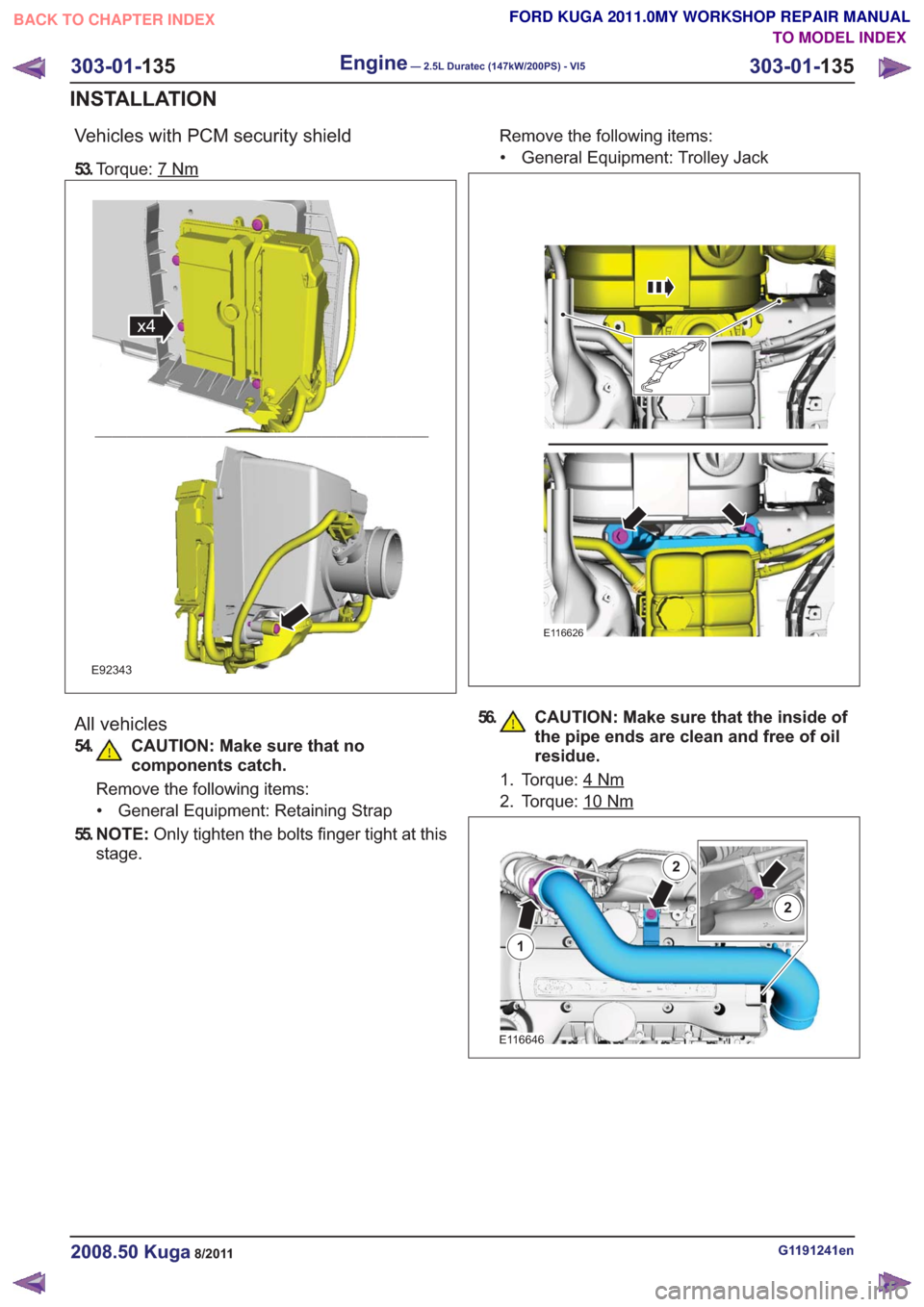
Vehicles with PCM security shield
53.Torque: 7Nm
x4x4
E92343
All vehicles
54. CAUTION: Make sure that no
components catch.
Remove the following items:
• General Equipment: Retaining Strap
55. N O T E : Only tighten the bolts finger tight at this
stage. Remove the following items:
• General Equipment: Trolley Jack
E116626
56. CAUTION: Make sure that the inside of the pipe ends are clean and free of oil
residue.
1. Torque: 4Nm
2. Torque: 10Nm
E116646
1
2
2
G1191241en2008.50 Kuga8/2011
303-01- 135
Engine— 2.5L Duratec (147kW/200PS) - VI5303-01-
135
INSTALLATION
TO MODEL INDEX
BACK TO CHAPTER INDEX
FORD KUGA 2011.0MY WORKSHOP REPAIR MANUAL
Page 1715 of 2057
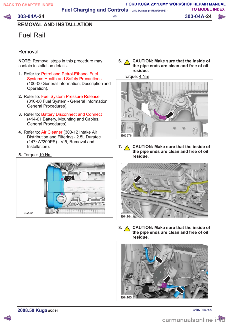
Fuel Rail
Removal
NOTE:Removal steps in this procedure may
contain installation details.
1. Refer to: Petrol and Petrol-Ethanol Fuel
Systems Health and Safety Precautions
(100-00 General Information, Description and
Operation).
2. Refer to: Fuel System Pressure Release
(310-00 Fuel System - General Information,
General Procedures).
3. Refer to: Battery Disconnect and Connect
(414-01 Battery, Mounting and Cables,
General Procedures).
4. Refer to: Air Cleaner (303-12 Intake Air
Distribution and Filtering - 2.5L Duratec
(147kW/200PS) - VI5, Removal and
Installation).
5. Torque: 10
Nm
x2x2
E92954
6. CAUTION: Make sure that the inside of
the pipe ends are clean and free of oil
residue.
Torque: 4Nm
E63576
7. CAUTION: Make sure that the inside ofthe pipe ends are clean and free of oil
residue.
E64164
8. CAUTION: Make sure that the inside ofthe pipe ends are clean and free of oil
residue.
E64165
G1079057en2008.50 Kuga8/2011
303-04A- 24
Fuel Charging and Controls
— 2.5L Duratec (147kW/200PS) -
VI5
303-04A- 24
REMOVAL AND INSTALLATION
TO MODEL INDEX
BACK TO CHAPTER INDEX
FORD KUGA 2011.0MY WORKSHOP REPAIR MANUAL
Page 1719 of 2057
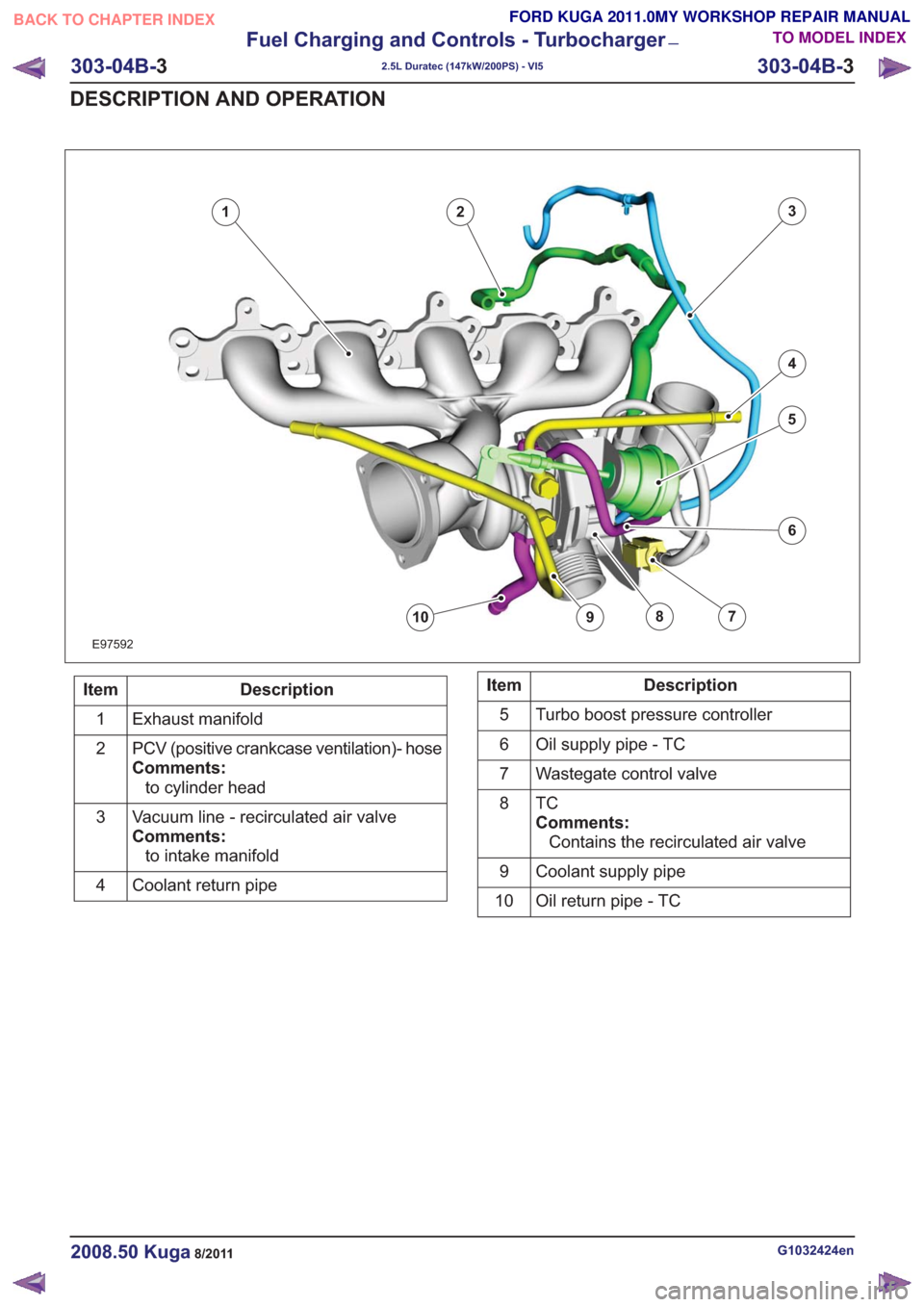
6
79108
123
4
5
6
79108
E97592
Description
Item
Exhaust manifold
1
PCV (positive crankcase ventilation)- hose
Comments:to cylinder head
2
Vacuum line - recirculated air valve
Comments:to intake manifold
3
Coolant return pipe
4Description
Item
Turbo boost pressure controller
5
Oil supply pipe - TC
6
Wastegate control valve
7
TC
Comments:Contains the recirculated air valve
8
Coolant supply pipe
9
Oil return pipe - TC
10
G1032424en2008.50 Kuga8/2011
303-04B- 3
Fuel Charging and Controls - Turbocharger
—
2.5L Duratec (147kW/200PS) - VI5
303-04B- 3
DESCRIPTION AND OPERATION
TO MODEL INDEX
BACK TO CHAPTER INDEX
FORD KUGA 2011.0MY WORKSHOP REPAIR MANUAL
Page 1720 of 2057
Turbocharger – Overview
Turbocharger(s)
CAUTION: Do not switch off the engine
while it is running at high speed. If the
engine is switched off while it is running
at high speed, the turbocharger will
continue to run after the engine oil
pressure has already dropped to zero. This
will cause premature wear in the
turbocharger bearings.
A TC consists of an exhaust turbine located in the
exhaust gas flow, this turbine is connected to a
compressor by a shaft. The turbine is made to
rotate by the exhaust gas flow from the engine and
thus drives the compressor. The compressor
increases the pressure in the engine intake tract
so that a greater mass of air enters the cylinder
during the intake stroke.
The turbine housing of the TC is integrated into the
exhaust manifold. This construction offers
thermodynamic advantages compared with the
usual construction, the maximum exhaust
temperature is up to 1050°C.
The maximum boost pressure is 0.65 bar.
The exhaust manifold is secured to the exhaust
side of the cylinder head with 12 self-locking nuts.
The exhaust manifold gasket is a multi-layer steel
gasket and cannot be reused. In order to
compensate for the thermal expansion of the
exhaust manifold, the flange of the TC is provided
with two grooves.
The TC and the exhaust manifold are joined by a
hose clip. The hose clip must not be loosened or
removed. The TC and the exhaust manifold are
not available as separate replacement parts,
exchange is only possible as a complete unit.
The turbocharger heat shield is secured to the
exhaust manifold by four bolts. Two of the bolts
have spring washers underneath their heads.
During removal, make a note of the installation
location of the spring washers to refer to during
installation.
The recirculated air valve is built into the TC
housing and cannot be changed.
The Ford diagnostic unit can test the operation of
the wastegate control valve using actuator
diagnosis.
The boost pressure regulator is set in the factory.
Adjustments to the boost pressure regulator must never be attempted. A red colored seal is applied
to the adjustment nut of the operating rod, in order
to monitor the factory setting of the boost pressure.
The bearings of the TC are lubricated with engine
oil. The engine oil passes from the cylinder block
through the oil supply pipe to the TC. The oil is
returned to the oil pan through the oil return pipe,
The TC is cooled by the engine coolant circuit.
When installing hoses and lines, make certain that
their ends are free of oil residues and dirt.
G1032425en2008.50 Kuga8/2011
303-04B-
4
Fuel Charging and Controls - Turbocharger
—
2.5L Duratec (147kW/200PS) - VI5
303-04B- 4
DESCRIPTION AND OPERATION
TO MODEL INDEX
BACK TO CHAPTER INDEX
FORD KUGA 2011.0MY WORKSHOP REPAIR MANUAL