dtc FORD KUGA 2011 1.G User Guide
[x] Cancel search | Manufacturer: FORD, Model Year: 2011, Model line: KUGA, Model: FORD KUGA 2011 1.GPages: 2057
Page 291 of 2057
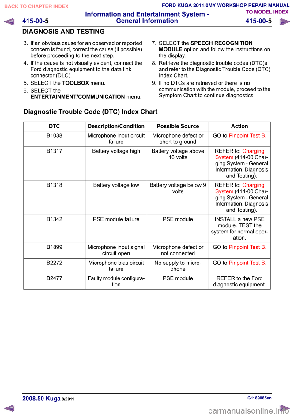
3. If an obvious cause for an observed or reported
concern is found, correct the cause (if possible)
before proceeding to the next step.
4. If the cause is not visually evident, connect the Ford diagnostic equipment to the data link
connector (DLC).
5. SELECT the TOOLBOXmenu.
6. SELECT the ENTERTAINMENT/COMMUNICATION menu.7. SELECT the
SPEECH RECOGNITION
MODULE option and follow the instructions on
the display.
8. Retrieve the diagnostic trouble codes (DTC)s and refer to the Diagnostic Trouble Code (DTC)
Index Chart.
9. If no DTCs are retrieved or there is no communication with the module, proceed to the
Symptom Chart to continue diagnostics.
Diagnostic Trouble Code (DTC) Index Chart Action
Possible Source
Description/Condition
DTC
GO toPinpoint Test B.
Microphone defect or
short to ground
Microphone input circuit
failure
B1038
REFER to:Charging
System (414-00 Char-
ging System - General
Information, Diagnosis and Testing).
Battery voltage above
16 volts
Battery voltage high
B1317
REFER to:Charging
System (414-00 Char-
ging System - General
Information, Diagnosis and Testing).
Battery voltage below 9
volts
Battery voltage low
B1318
INSTALL a new PSEmodule. TEST the
system for normal oper- ation.
PSE module
PSE module failure
B1342
GO toPinpoint Test B.
Microphone defect or
not connected
Microphone input signal
circuit open
B1899
GO toPinpoint Test B.
No supply to micro-
phone
Microphone bias circuit
failure
B2272
REFER to the Ford
diagnostic equipment.
PSE module
Faulty module configura-
tion
B2477 G1189085en
2008.50 Kuga 8/2011 415-00-5
Information and Entertainment System -
General Information
415-00-5
DIAGNOSIS AND TESTINGTO MODEL INDEX
BACK TO CHAPTER INDEX
FORD KUGA 2011.0MY WORKSHOP REPAIR MANUAL
Page 292 of 2057
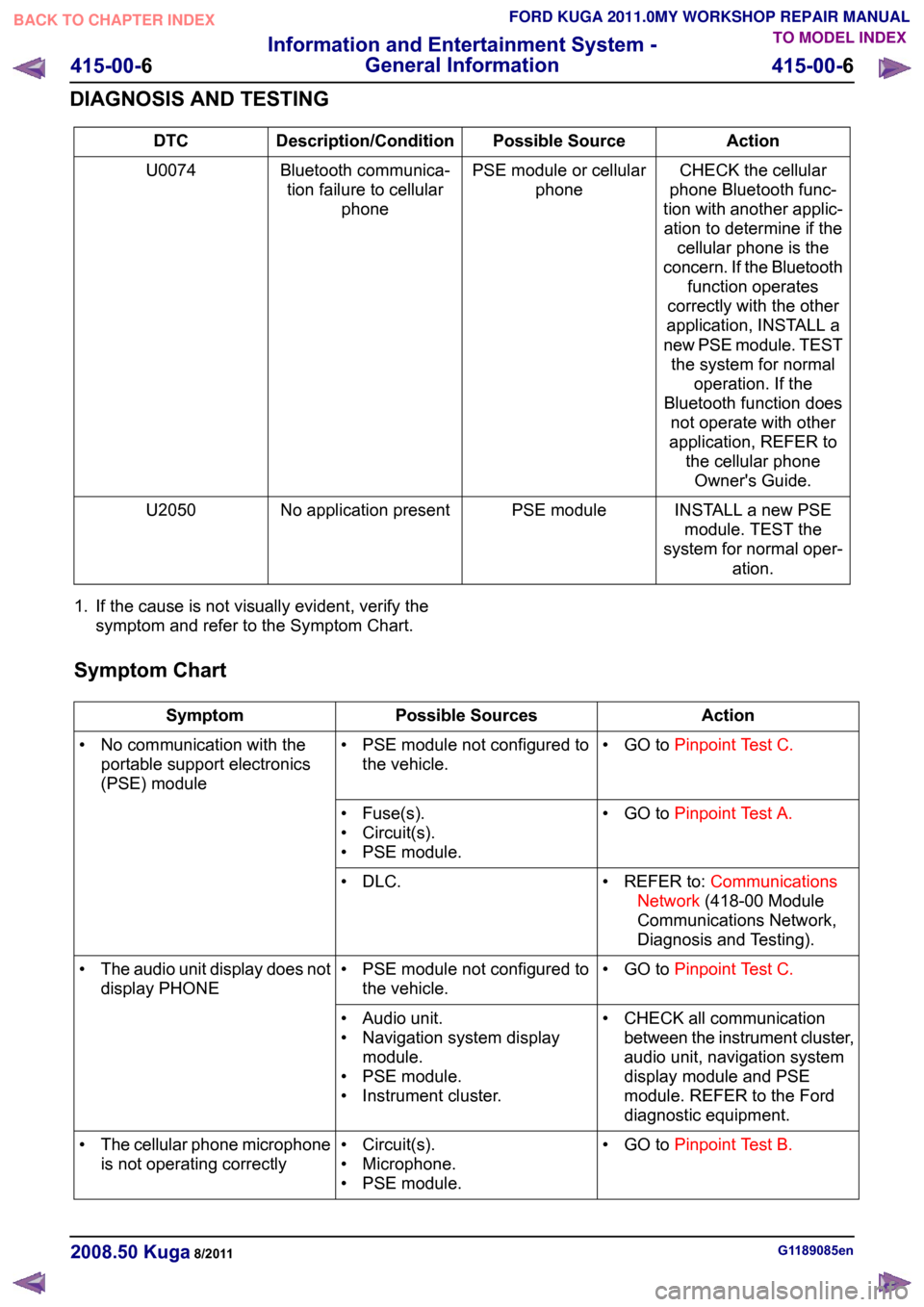
Action
Possible Source
Description/Condition
DTC
CHECK the cellular
phone Bluetooth func-
tion with another applic- ation to determine if the cellular phone is the
concern. If the Bluetooth function operates
correctly with the other
application, INSTALL a
new PSE module. TEST the system for normal operation. If the
Bluetooth function does not operate with other
application, REFER to the cellular phoneOwner's Guide.
PSE module or cellular
phone
Bluetooth communica-
tion failure to cellular phone
U0074
INSTALL a new PSEmodule. TEST the
system for normal oper- ation.
PSE module
No application present
U2050
1. If the cause is not visually evident, verify the symptom and refer to the Symptom Chart.
Symptom Chart Action
Possible Sources
Symptom
• GO toPinpoint Test C.
• PSE module not configured to
the vehicle.
• No communication with the
portable support electronics
(PSE) module
• GO toPinpoint Test A.
• Fuse(s).
• Circuit(s).
• PSE module.
• REFER to:Communications
Network (418-00 Module
Communications Network,
Diagnosis and Testing).
• DLC.
• GO toPinpoint Test C.
• PSE module not configured to
the vehicle.
•
The audio unit display does not
display PHONE
• CHECK all communicationbetween the instrument cluster,
audio unit, navigation system
display module and PSE
module. REFER to the Ford
diagnostic equipment.
• Audio unit.
• Navigation system display
module.
• PSE module.
• Instrument cluster.
• GO toPinpoint Test B.
• Circuit(s).
• Microphone.
• PSE module.
•
The cellular phone microphone
is not operating correctly G1189085en
2008.50 Kuga 8/2011 415-00-6
Information and Entertainment System -
General Information
415-00-6
DIAGNOSIS AND TESTINGTO MODEL INDEX
BACK TO CHAPTER INDEX
FORD KUGA 2011.0MY WORKSHOP REPAIR MANUAL
Page 1840 of 2057
E77584
NOTE:Due to static charging, measurements
inside the transaxle using a multimeter are
prohibited.
Stored DTCs in the engine management system
may affect transmission control. As a result, faults
in the transmission control system and engine
management system must be rectified in
accordance with the symptom-based diagnosis in
FordEtis IDS.
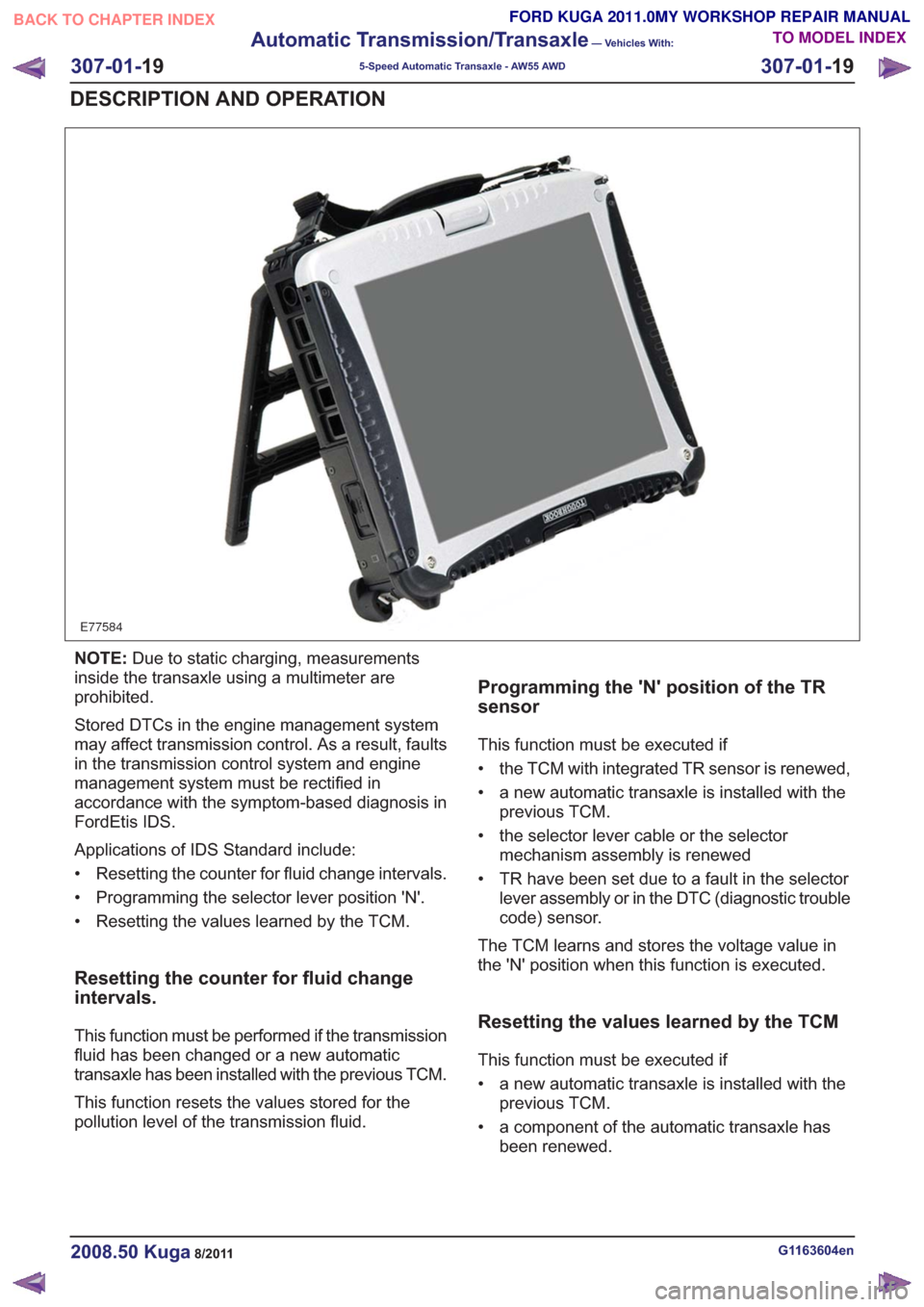
Applications of IDS Standard include:
• Resetting the counter for fluid change intervals.
• Programming the selector lever position 'N'.
• Resetting the values learned by the TCM.
Resetting the counter for fluid change
intervals.
This function must be performed if the transmission
fluid has been changed or a new automatic
transaxle has been installed with the previous TCM.
This function resets the values stored for the
pollution level of the transmission fluid.
Programming the 'N' position of the TR
sensor
This function must be executed if
• the TCM with integrated TR sensor is renewed,
• a new automatic transaxle is installed with the previous TCM.
• the selector lever cable or the selector mechanism assembly is renewed
• TR have been set due to a fault in the selector lever assembly or in the DTC (diagnostic trouble
code) sensor.
The TCM learns and stores the voltage value in
the 'N' position when this function is executed.
Resetting the values learned by the TCM
This function must be executed if
• a new automatic transaxle is installed with the previous TCM.
• a component of the automatic transaxle has been renewed.
G1163604en2008.50 Kuga8/2011
307-01- 19
Automatic Transmission/Transaxle
— Vehicles With:
5-Speed Automatic Transaxle - AW55 AWD
307-01- 19
DESCRIPTION AND OPERATION
TO MODEL INDEX
BACK TO CHAPTER INDEX
FORD KUGA 2011.0MY WORKSHOP REPAIR MANUAL
Page 1851 of 2057
select-shift switch module transmits a downshift
signal to the TCM.
If you move the gear selector lever backwards (+),
an upshift signal is transmitted to the TCM. In the
instrument cluster, the symbol when the selector
lever is in the 'S' position changes from 'D' to the
current gear, for example 3.
The TCM transmits a signal to the select-shift
switch module to switch on the light emitting diode
for 'S' and to switch off all other light emitting
diodes. The TCM decides whether the shift process
is possible.
If the shift process is permitted, then the various
valves are activated according to the intended
combination for each gear.
In certain situations however, the TCM determines
the gear shifting. The following applies:
• If the vehicle is stationary, only 1st, 2nd and 3rdgears can be selected. 4th gear can be selected
at speeds over 30 km/h and 5th gear at speeds
over 40 km/h.
• The kickdown function is only available in the automatic transmission range 'D'
• Automatic gear changes into the next higher or next lower gear occur at fixed vehicle speeds
and fixed engine speeds
• The permitted engine speed for manual change down agree with that for the kickdown change
up, i.e. an engine speed of approximately 6000
rpm.
• If the temperature inside the transmission rises too high, the TCM takes control of the shift
decisions in order to select a gear in which
activation of torque converter lockup at the
current speed is possible
• Torque converter lockup is possible in 3rd, 4th and 5th gear. (1st and 2nd gears do not have
torque converter lockup)
The signal that specifies the position of the lever
to the select-shift switch module is generated as
follows in the selector lever position 'S': there is a
Hall sensor at the printed circuit board for the
module for each of the three selector lever
positions. A permanent magnet on the cover in the
selector lever affects the output signals to the
control module from the sensors. The control
module recognizes the position of the lever by the
differences in the signal properties.Selector lever from 'N' to 'R' position
The TCM only permits shifting to reverse gear if
the vehicle speed is less than 4.35 mph.
If the vehicle speed is greater than 7 km/h (approx.
4.35 mph), the clutch (C2) and the multi-plate brake
(B3) are not activated and the gearshift is thus
prevented.
Self-test and Diagnosis
The TCM monitors all the transaxle sensors and
electronic components including the PCM. If a fault
occurs, the driver is informed via a warning
indicator and a text message in the instrument
cluster. Faults are stored as DTCs in the fault
memory of the TCM and can be read out and
cleared using the IDS.
Temperature controlled torque converter
lockup
If heavy load and high ambient temperatures cause
an abnormal rise in the transmission temperature,
torque converter lockup is activated as often as
possible (temperature controlled lockup).
This reduces the slip and the heat developed in
the transmission. When the temperature drops
below +20 °C, torque converter lockup is not used.
Slip locking
When changing gear this function makes it possible
for the gears to engage more smoothly with
reduced vibration and less noise. In this mode, the
torque converter clutch is activated but not fully
locked.
The following conditions must be met for the
function to activate:
• Gear selector lever in position D or S.
• Gear 3, 4 or 5.
• The transmission input speed is 1100 rpm or more and the throttle plate opening 20 - 35%.
• The transmission fluid temperature is 40 - 120 °C.
Hill climbing
The TCM can change the shift pattern slightly when
driving uphill to avoid changing gear too often.
G1163605en2008.50 Kuga8/2011
307-01- 30
Automatic Transmission/Transaxle
— Vehicles With:
5-Speed Automatic Transaxle - AW55 AWD
307-01- 30
DESCRIPTION AND OPERATION
TO MODEL INDEX
BACK TO CHAPTER INDEX
FORD KUGA 2011.0MY WORKSHOP REPAIR MANUAL
Page 1875 of 2057
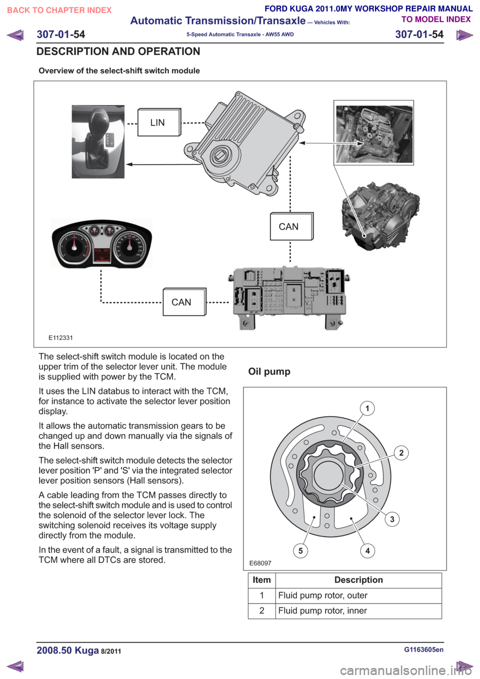
Overview of the select-shift switch module
E112331
The select-shift switch module is located on the
upper trim of the selector lever unit. The module
is supplied with power by the TCM.
It uses the LIN databus to interact with the TCM,
for instance to activate the selector lever position
display.
It allows the automatic transmission gears to be
changed up and down manually via the signals of
the Hall sensors.
The select-shift switch module detects the selector
lever position 'P' and 'S' via the integrated selector
lever position sensors (Hall sensors).
A cable leading from the TCM passes directly to
the select-shift switch module and is used to control
the solenoid of the selector lever lock. The
switching solenoid receives its voltage supply
directly from the module.
In the event of a fault, a signal is transmitted to the
TCM where all DTCs are stored.
Oil pump
E68097
1
2
3
45
Description
Item
Fluid pump rotor, outer
1
Fluid pump rotor, inner
2
G1163605en2008.50 Kuga8/2011
307-01- 54
Automatic Transmission/Transaxle
— Vehicles With:
5-Speed Automatic Transaxle - AW55 AWD
307-01- 54
DESCRIPTION AND OPERATION
TO MODEL INDEX
BACK TO CHAPTER INDEX
FORD KUGA 2011.0MY WORKSHOP REPAIR MANUAL
Page 2008 of 2057
control saves the current speed as the target
speed.
Cruise control goes into STANDBY mode in the
following situations:
• Operation of the brake pedal
• Operation of the clutch pedal
• Operation of the parking brake
• If the driver operates the accelerator pedal andthe saved target speed is subsequently
exceeded for more than 5 minutes.
• Pressing any cruise control button for more than 2 minutes
• Intervention by the traction control or electronic stability program (for longer than 40 ms)
• Shifting of the gear selector lever to the "N" position (vehicles with automatic transmission
only)
• Minimum speed falls below 40 km/h.
• Occurrence of particular DTC (diagnostic trouble code)
• faulty signal from the backup lamp switch
Cruise control is switched off when the "OFF"
button is pressed.
If the accelerator pedal is pressed down, the
vehicle speed increases. As soon as the pedal is
released, the speed falls to the saved target value. The following components supply the signals
needed by the cruise control:
• The APP sensor.
– The APP sensor identifies the currentposition of the accelerator pedal and sends
a PWM (pulse width modulation) signal to
the PCM and an analog DC (direct current)
signal to the GEM.
– If one or both of the APP sensors fails, a fault is stored in the PCM fault memory and cruise
control cannot be activated.
• BPP switch – The BPP switch tells the PCM whether thevehicle is being braked. In its rest state the
switch is closed and sends an earth signal
to the GEM. This signal is sent via the CAN
to the PCM.
– The brake light switch is likewise connected to the GEM and is opened in the rest state.
When the vehicle is braked, the brake light
switch sends a signal to the GEM. This
compares the signals from the BPP switch
and the brake light switch. If a discrepancy
occurs, a fault is stored in the error memory
of the GEM. Cruise control cannot be
activated.
• CPP switch – The CPP switch sends a ground signal to theGEM as soon as the clutch is operated. This
signal is passed on by the GEM via the CAN
bus to the PCM. This then supplies the signal
to the cruise control.
– If the CPP switch is incorrectly installed or set, cruise control cannot be activated.
• Wheel speed sensors – The wheel speed sensors record the speedof all the wheels. The recorded speed values
are sent to the ABS module via a hard-wired
connection. The ABS module calculates a
vehicle speed signal (VS signal) from the
speed values and the wheel diameter. This
vehicle speed signal is transferred via the
CAN bus to the PCM and supplied to the
cruise control. If the vehicle speed signal is
faulty, cruise control cannot be activated.
G1044191en2008.50 Kuga8/2011
310-03- 5
Speed Control
310-03- 5
DESCRIPTION AND OPERATION
TO MODEL INDEX
BACK TO CHAPTER INDEX
FORD KUGA 2011.0MY WORKSHOP REPAIR MANUAL
Page 2010 of 2057
Speed Control
Inspection and Verification
1. Verify the customer concern by operating thesystem.
2. Visually inspect for obvious signs of mechanical or electrical damage.
Visual Inspection Chart
Electrical
Mechanical
– Fuse(s)
– Connections
– Wiring harness
– Clockspring
– Loose or corrodedelectrical
connector(s)
– Speed control switch
– Brake pedal position (BPP) deactivation
switch
– Clutch pedal posi- tion (CPP) deactiva-
tion Switch
– Powertrain control module (PCM)
– Central junction box (CJB)
– Brake pedal
– Clutch pedal
3. NOTE: Not all passenger junction box (PJB) variants support the speed control system.
NOTE: If the PJB is configured for speed control
disable, speed control operation is not transmitted,
no Diagnostic Trouble Codes (DTCs) are
generated.
If an obvious cause for an observed or reported
concern is found, correct the cause (if possible)
before proceeding to the next step.
4. If the cause is not visually evident, verify the symptom and refer to the diagnostic tab within
the Ford approved diagnostic tool.
G1054908en2008.50 Kuga8/2011
310-03- 7
Speed Control
310-03- 7
DIAGNOSIS AND TESTING
TO MODEL INDEX
BACK TO CHAPTER INDEX
FORD KUGA 2011.0MY WORKSHOP REPAIR MANUAL
Page 2038 of 2057
Fault Memory Interrogation without
diagnostics unit - vehicles with
automatic temperature control
NOTE:On vehicles equipped with a DVD
navigation system with touchscreen, the fault
memory can only be interrogated using the Ford
diagnostic tool.
The climate control and heating system features
a on-board diagnosis function which can detect
and store both current permanent faults as well as
intermittent faults which have occurred during
normal operation of the vehicle. It is also possible
to read out these faults via the display on the
control panel of the climate control system. To read
out the fault memory, the ignition key must be
turned to the "ON" position and the battery voltage
must be between 9 V and 16 V.
To activate the on-board diagnosis at the control
panel for the climate control system, PRESS the
"OFF" and "FOOTWELL" buttons simultaneously
for exactly 2 seconds, then PRESS "AUTO" within
1.5 seconds. The on-board diagnosis which then
starts lasts a few seconds. An animated display
appears in the display of the control panel for the
climate control system during this time. Any faults
found are displayed on both displays of the control
panel for the climate control system in the form of
trouble codes.
To read out saved errors at the control panel for
the climate control system, PRESS the "OFF" and
"FOOTWELL" buttons simultaneously for exactly
2 seconds, then PRESS "HEAD AREA" within 1.5
seconds. Any stored faults are shown on the
display of the control panel for the climate control
system and should be noted for safety reasons.
By PRESSING the "DEFROST" button, the fault
memory is cleared and diagnosis mode is ended.
To end the diagnostic mode without clearing the
DTCs, PRESS any other operating button on the
control panel for the climate control system.
To read out the software version at the control
panel for the climate control system, PRESS the
"OFF" and "FOOTWELL" buttons simultaneously
for exactly 2 seconds, then PRESS "A/C" within
1.5 seconds. The software version is shown on the
display of the control panel for the climate control
system. The output mode can be exited by
PRESSING any button on the control panel for the
climate control system.
Switch over from Celsius to Fahrenheit
The switch from Celsius to Fahrenheit is performed
on the display of the instrument cluster and is then
transmitted via the CAN bus to the module of the
two-zone air conditioning system.
G1034945en2008.50 Kuga8/2011
412-01- 11
Climate Control
412-01- 11
DESCRIPTION AND OPERATION
TO MODEL INDEX
BACK TO CHAPTER INDEX
FORD KUGA 2011.0MY WORKSHOP REPAIR MANUAL