reversing lamp FORD KUGA 2011 1.G User Guide
[x] Cancel search | Manufacturer: FORD, Model Year: 2011, Model line: KUGA, Model: FORD KUGA 2011 1.GPages: 2057
Page 376 of 2057

Daytime Running Lamps (DRL)
Refer to Wiring Diagrams Section 417-04, for
schematic and connector information.
Special Tool(s)
Terminal Probe Kit
29-011ADescription of operation
A diagnosis of the generic electronic module (GEM)
can be performed with the Ford approved
diagnostic tool. Furthermore, an integrated service
mode enables testing of the input and output
signals without the need for further tools. To enable
activation of service mode:
• switch off the ignition,
• switch off all other electrical consumers,
• apply the handbrake,
• shift to neutral
• and close the doors.
Activating the service mode
Proceed as follows to activate the service mode:
•
OPERATE the switch of the heated rear window
and HOLD IT THERE
• Turn on the ignition.
• RELEASE the switch of the heated rear window
A signal sounds and the turn signal lamps come
on to indicate that service mode has been
successfully activated.
NOTE: If the alarm is activated (in vehicles fitted
with an anti-theft alarm system), service mode
cannot be activated.
Inputs
SWITCH the windshield wiper switch to the "Off"
position to test the input signals. The following is
a list of the switch signals to be tested, in no
particular order:
• Turn signals (right, left, hazard warning lights)
• Windshield wiper stage I
• Windshield wiper stage II
• Windshield washer system • Rear window wiper
• Rear window washer system
• Doors open/closed
• Remote control for central locking with double
locking
• Hood open/closed (in vehicles equipped with an anti-theft alarm system)
• Tailgate open/closed
• A/C request signal
• Heated windscreen (if fitted)
• Parking Brake
• Brake reservoir fluid level
• Speed control system
• Autolamps
• dipped beam
• main beam
• headlamp flasher
• Marker Lamps
• Reversing lamp
• Liftgate release
• Ignition switch, terminal 15 (turn key to 0 position, then turn key to II position.)
An acoustic signal sounds and the turn signal
lamps flash to indicate receipt of each input signal
by the generic electronic module.
Test the windshield wiper "intermittent mode" stage
input signal (only vehicles with adjustable
intermittent mode)
The windshield wiper switch must be switched to
"intermittent mode" in order to test the input signal.
The delay times of the input signals can then be
tested by operating the rotary switch. Each change
of the rotary switch position is indicated by an
acoustic signal and illumination of the turn signals.
Output signals
SWITCH the wiper switch to the "intermittent""
position to test the output signals. PRESSING the
heated rear window switch activates the output
signals in the following order:
a. Turn Indicator Left Hand
b. Turn Indicator Right Hand
c. main beam
d. dipped beam
e. Windshield wiper stage I
f. Windshield wiper stage II G1055032en
2008.50 Kuga 8/2011 417-04-2
Daytime Running Lamps (DRL)
417-04-2
DIAGNOSIS AND TESTINGTO MODEL INDEX
BACK TO CHAPTER INDEX
FORD KUGA 2011.0MY WORKSHOP REPAIR MANUAL29011A
Page 380 of 2057

Description
Item
Reversing camera module (RVC)
10
Keyless vehicle module (KVM)
11
All-wheel drive control unit
12
RDM - Driver's side
13
RCM (restraints control module)
14
DDM (driver door module)
15
Instrument Cluster
16 Description
Item
High intensity discharge headlamp module
(optional)
17
ABS (anti-lock brake system) module or
electronic stability program module
18
PCM (powertrain control module)
19
The EATC (electronic automatic
temperature control) control module
20
Electrohydraulic power steering module
21 G1072290en
2008.50 Kuga 8/2011 418-00-3
Module Communications Network
418-00-3
DESCRIPTION AND OPERATIONTO MODEL INDEX
BACK TO CHAPTER INDEX
FORD KUGA 2011.0MY WORKSHOP REPAIR MANUAL
Page 383 of 2057

Description
Item
Medium speed CAN (controller area
network) bus (MS-CAN)
A
High speed CAN bus (HS-CAN)
B
LIN (local interconnect network) bus
C
Terminating resistors
Drive
DLC (data link connector)
E
GEMRefer to Component Description: ABS
(page ?)
1
Fuel fired booster heater /programmable
fuel fired booster heater
2
The EATC control module
3
Reversing camera module (RVC)
4
Parking aid module (PAM)
5
DDM6
Front driver's side switch unit
7
Driver's side RDM
8
PDM (Passenger Door Module)
9
Passenger side RDM
10
Audio unit/navigation unit
11
CD changer
12 Description
Item
Navigation system module - vehicles
equipped with DVD navigation system with
touch screen (not communicating with the
diagnostic unit)
13
Navigation system display - vehicles
equipped with DVD navigation system with
touch screen (not communicating with the
diagnostic unit)
14
Control module for electronic auxiliary
equipment (BVC)
15
RCM16
Keyless vehicle module (KVM)
17
Instrument Cluster
18
PCM19
Fuel additive system module.
20
ABS module or electronic stability program
module
21
Yaw rate sensor/lateral acceleration
sensor
22
Headlamp Leveling Module
23
All-wheel drive control unit
24
Electrohydraulic power steering module
25
System Operation
General
In a communications network (data bus system),
various modules of different systems are connected
to one another via one or several lines.
The data bus system is used exclusively for
transmitting data between the connected modules,
as well as between the connected modules and
the Ford diagnostic unit.
In a data bus system, complete data blocks are
transmitted instead of single on/off pulses. In
addition to the actual information, these data blocks
also contain data regarding the address of the
module to be addressed, the size of the data block
and information for monitoring the content of each
individual data block.
Data bus systems offer various advantages: • Simplified data transmission between the
modules due to a standardized protocol
• Fewer sensors and connectors
• Improved diagnostic options
• Lower costs
The DLC is connected to the various data bus
systems and to the power supply via the standard
16-pin GEM. The signal for the module
programming is also transferred via the DLC.
In a data bus system, if there is a break in one or
both lines or there is a short to ground or to voltage,
then communication between the modules and
with the Ford diagnostic unit is disturbed or is no
longer possible at all.
In order to be able to establish communication with
one another, the modules of the individual systems G1030779en
2008.50 Kuga 8/2011 418-00-6
Module Communications Network
418-00-6
DESCRIPTION AND OPERATIONTO MODEL INDEX
BACK TO CHAPTER INDEX
FORD KUGA 2011.0MY WORKSHOP REPAIR MANUAL
Page 453 of 2057

• Reversing lamp
• Liftgate release
• Folding liftgate release
• Ignition switch, terminal 15 (turn key to 0
position, then turn key to II position.)
An acoustic signal sounds and the turn signal
lamps flash to indicate receipt of each input signal
by the generic electronic module.
Test the windshield wiper "intermittent mode"
stage input signal (only vehicles with adjustable
intermittent mode):
The windshield wiper switch must be switched to
"intermittent mode" in order to test the input signal.
The delay times of the input signals can then be
tested by operating the rotary switch. Each change
of the rotary switch position is indicated by an
acoustic signal and illumination of the turn signals.
Output signals
SWITCH the wiper switch to the "Intermittent"
position to test the output signals. PRESSING the
heated rear window switch activates the output
signals in the following order:
• Left-hand turn signal
• Right-hand turn signal
• Main beam
• Dipped beam
• Windshield wiper stage I
• Windshield wiper stage II
• Heated rear window
• Heater blower motor
• Headlamp washer system (vehicles with HID headlamps)
• Electric booster heater (if fitted)
• Autolamps (if fitted)
• Alarm horn (vehicles with alarm system)
• Rear window wiper
• Heated rear window relay
When the heated rear window switch is pressed
again, the test of the relevant signal is terminated.
When the heated rear window switch is pressed
once more, the test for the next signal in the list is
started.
Ending the service mode
The GEM automatically ends service mode 20
seconds after the last input or at a driving speed
of over 7km/h. However, service mode can be
manually ended at any time by proceeding as
follows: •
OPERATE the switch of the heated rear window
and HOLD IT THERE
• Switch off the ignition.
• RELEASE the switch of the heated rear window
3 signals sound and the turn signal lamps illuminate
to indicate that service mode has ended.
Resetting service mode
If, after completion of service mode, some functions
do not operate or do not operate properly, check
the following functions:
• Instrument cluster illumination, side marker lamps (side lights) and licence plate lamp in
automatic headlamps mode
• Rear wiper
• Headlamp washer assembly
• Electric booster heater
• Alarm horn
• Heated windshield
If one or more of the listed functions is not OK, it's
possible that the cause of the fault is due to not
exiting service mode properly. To reactivate the
functions correctly, perform the following steps:
1. Switch off the ignition.
2. SWITCH OFF the switch for the windscreen wash/wipe system
3. OPERATE the switch of the heated rear window
and HOLD IT THERE
4. SWITCH ON the ignition.
5. RELEASE the heated rear window switch (an acoustic signal will sound if activation has been
performed correctly)
6. SWITCH the windscreen wash/wipe switch to the "Intermittent wipe" position
7. OPERATE the heated rear window switch 6 times (the main beam headlamps switch on and
off automatically)
8. SWITCH OFF the switch for the windscreen wash/wipe system
9. OPERATE the switch of the heated rear window
and HOLD IT THERE
10. Switch off the ignition.
11. RELEASE the heated rear window switch (three
acoustic signals will sound if activation has been
performed correctly)
After completion of the work, check all the
functions. G1030787en
2008.50 Kuga 8/2011 419-10-3
Multifunction Electronic Modules
419-10-3
DESCRIPTION AND OPERATIONTO MODEL INDEX
BACK TO CHAPTER INDEX
FORD KUGA 2011.0MY WORKSHOP REPAIR MANUAL
Page 461 of 2057

Generic Electronic Module (GEM)
Refer to Wiring Diagrams Section 419-10, for
schematic and connector information.
Special Tool(s) / General Equipment
Terminal Probe Kit
418-S035Digital multimeter
Ford approved diagnostic tool
Description of operation
A diagnosis of the generic electronic module (GEM)
can be performed with the Ford approved
diagnostic tool. Furthermore, an integrated service
mode enables testing of the input and output
signals without the need for further tools. To enable
activation of service mode:
• Switch off the ignition
• Switch off all other electrical consumers
• Apply the handbrake
• Shift to neutral
• Close the doors.
Activate service mode
Proceed as follows to activate service mode:
• PRESS and HOLD the switch of the heated rear
window
• SWITCH ON the ignition.
• RELEASE the switch of the heated rear window
A signal sounds and the turn signal lamps
illuminate to indicate that service mode has been
successfully activated.
NOTE: If the alarm is armed (in vehicles fitted with
an anti-theft alarm system), service mode cannot
be activated.
Input signals
SWITCH the windshield wiper switch to the "Off"
position to test the input signals. The following is
a list of the switch signals to be tested, in no
particular order: • Turn signals (right, left, hazard warning lights)
• Windshield wiper stage I
• Windshield wiper stage II
• Windshield washer system
• Rear window wiper
• Rear window washer system
• Doors open/closed
• Door key cylinder set/reset switch
• Remote control for central locking with double
locking
• Hood up/down (in vehicles fitted with anti-theft alarm system)
• Tailgate open/closed
• Mini liftgate open/closed
• Manual A/C request signal
• Manual AUX heater request signal
• Heated windshield (if fitted)
• Parking brake
• Brake fluid level
• Cruise control system
• Autolamps
• Dipped beam
• Main beam
• Headlamp flasher
• Side lights
• Reversing lamp
• Tailgate release
• Mini liftgate release
• Interior scanning system
• Ignition switch, terminal 15 (turn key to 0 position, then turn key to II position.)
An acoustic signal sounds and the turn signal
lamps flash to indicate receipt of each input signal
by the generic electronic module.
Test the windshield wiper "intermittent mode" stage
input signal (only vehicles with adjustable
intermittent mode)
The windshield wiper switch must be switched to
"intermittent mode" in order to test the input signal.
The delay times of the input signals can then be
tested by operating the rotary switch. Each change
of the rotary switch position is indicated by an
acoustic signal and illumination of the turn signals. G1055084en
2008.50 Kuga 8/2011 419-10-11
Multifunction Electronic Modules
419-10-11
DIAGNOSIS AND TESTINGTO MODEL INDEX
BACK TO CHAPTER INDEX
FORD KUGA 2011.0MY WORKSHOP REPAIR MANUAL29011A
Page 1881 of 2057

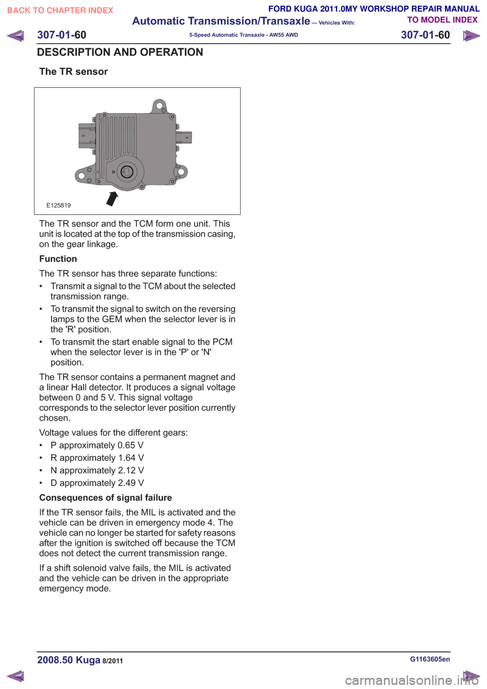
The TR sensor
E125819
The TR sensor and the TCM form one unit. This
unit is located at the top of the transmission casing,
on the gear linkage.
Function
The TR sensor has three separate functions:
• Transmit a signal to the TCM about the selectedtransmission range.
• To transmit the signal to switch on the reversing lamps to the GEM when the selector lever is in
the 'R' position.
• To transmit the start enable signal to the PCM when the selector lever is in the 'P' or 'N'
position.
The TR sensor contains a permanent magnet and
a linear Hall detector. It produces a signal voltage
between 0 and 5 V. This signal voltage
corresponds to the selector lever position currently
chosen.
Voltage values for the different gears:
• P approximately 0.65 V
• R approximately 1.64 V
• N approximately 2.12 V
• D approximately 2.49 V
Consequences of signal failure
If the TR sensor fails, the MIL is activated and the
vehicle can be driven in emergency mode 4. The
vehicle can no longer be started for safety reasons
after the ignition is switched off because the TCM
does not detect the current transmission range.
If a shift solenoid valve fails, the MIL is activated
and the vehicle can be driven in the appropriate
emergency mode.
G1163605en2008.50 Kuga8/2011
307-01- 60
Automatic Transmission/Transaxle
— Vehicles With:
5-Speed Automatic Transaxle - AW55 AWD
307-01- 60
DESCRIPTION AND OPERATION
TO MODEL INDEX
BACK TO CHAPTER INDEX
FORD KUGA 2011.0MY WORKSHOP REPAIR MANUAL
Page 2009 of 2057

• Parking brake switch.– The parking brake switch is hard-wired to theGEM. The parking brake switch sends a
signal to the GEM when the parking brake is
operated. The GEM activates the parking
brake indicator lamp in the instrument cluster.
If the parking brake indicator lamp is lit,
cruise control cannot be activated.
• Back-up light switch – The backup lamp switch is hard-wired to the GEM. The backup lamp switch sends a signal
to the GEM when reverse gear is engaged.
The GEM activates the reversing lamp.
Cruise control cannot be activated when
reverse gear is engaged.
Component Description
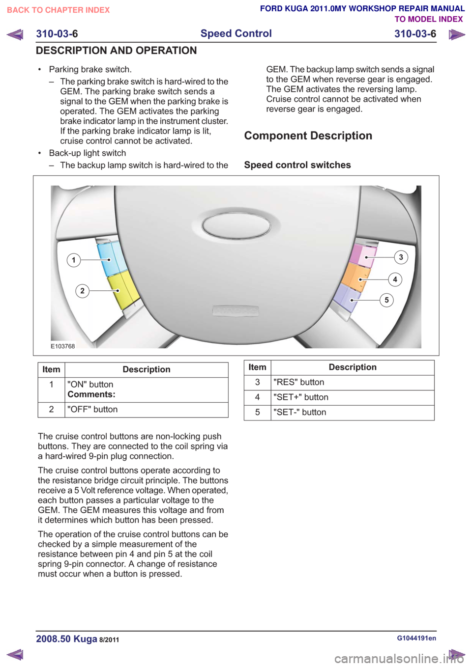
Speed control switches
E103768
3
4
5
1
2
Description
Item
"ON" button
Comments:
1
"OFF" button
2Description
Item
"RES" button
3
"SET+" button
4
"SET-" button
5
The cruise control buttons are non-locking push
buttons. They are connected to the coil spring via
a hard-wired 9-pin plug connection.
The cruise control buttons operate according to
the resistance bridge circuit principle. The buttons
receive a 5 Volt reference voltage. When operated,
each button passes a particular voltage to the
GEM. The GEM measures this voltage and from
it determines which button has been pressed.
The operation of the cruise control buttons can be
checked by a simple measurement of the
resistance between pin 4 and pin 5 at the coil
spring 9-pin connector. A change of resistance
must occur when a button is pressed.
G1044191en2008.50 Kuga8/2011
310-03- 6
Speed Control
310-03- 6
DESCRIPTION AND OPERATION
TO MODEL INDEX
BACK TO CHAPTER INDEX
FORD KUGA 2011.0MY WORKSHOP REPAIR MANUAL