reversing lamp FORD KUGA 2011 1.G Workshop Manual
[x] Cancel search | Manufacturer: FORD, Model Year: 2011, Model line: KUGA, Model: FORD KUGA 2011 1.GPages: 2057
Page 335 of 2057
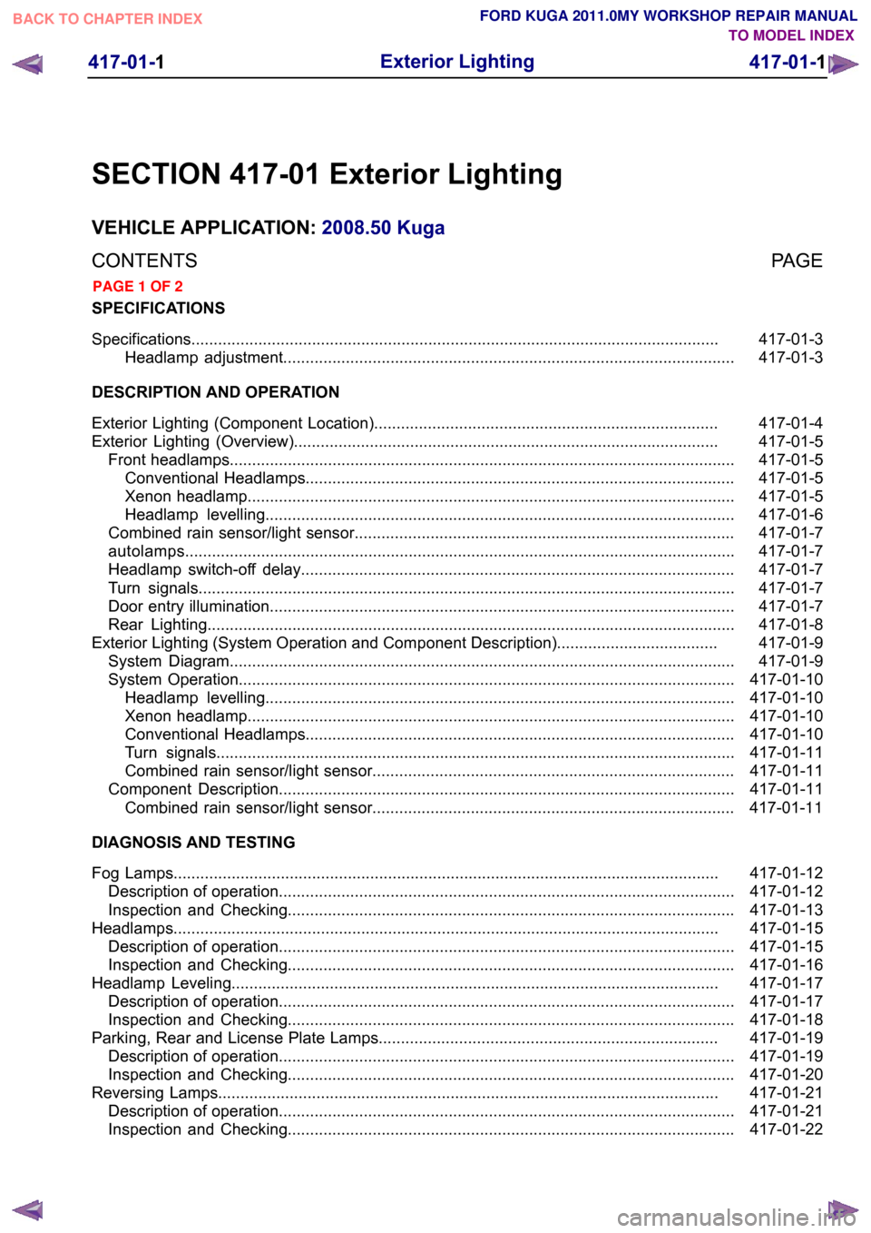
SECTION 417-01 Exterior Lighting
VEHICLE APPLICATION:
2008.50 Kuga
PAGE
CONTENTS
SPECIFICATIONS
417-01-3
Specifications ......................................................................................................................
417-01-3
Headlamp adjustment.....................................................................................................
DESCRIPTION AND OPERATION 417-01-4
Exterior Lighting (Component Location).............................................................................
417-01-5
Exterior Lighting (Overview)...............................................................................................
417-01-5
Front headlamps.................................................................................................................
417-01-5
Conventional Headlamps................................................................................................
417-01-5
Xenon headlamp.............................................................................................................
417-01-6
Headlamp levelling.........................................................................................................
417-01-7
Combined rain sensor/light sensor.....................................................................................
417-01-7
autolamps ...........................................................................................................................
417-01-7
Headlamp switch-off delay.................................................................................................
417-01-7
Turn signals........................................................................................................................
417-01-7
Door entry illumination........................................................................................................
417-01-8
Rear Lighting......................................................................................................................
417-01-9
Exterior Lighting (System Operation and Component Description)....................................
417-01-9
System Diagram.................................................................................................................
417-01-10
System Operation...............................................................................................................
417-01-10
Headlamp levelling.........................................................................................................
417-01-10
Xenon headlamp.............................................................................................................
417-01-10
Conventional Headlamps................................................................................................
417-01-11
Turn signals....................................................................................................................
417-01-11
Combined rain sensor/light sensor.................................................................................
417-01-11
Component Description......................................................................................................417-01-11Combined rain sensor/light sensor.................................................................................
DIAGNOSIS AND TESTING 417-01-12
Fog Lamps..........................................................................................................................
417-01-12
Description of operation......................................................................................................
417-01-13
Inspection and Checking....................................................................................................
417-01-15
Headlamps..........................................................................................................................
417-01-15
Description of operation......................................................................................................
417-01-16
Inspection and Checking....................................................................................................
417-01-17
Headlamp Leveling.............................................................................................................
417-01-17
Description of operation......................................................................................................
417-01-18
Inspection and Checking....................................................................................................
417-01-19
Parking, Rear and License Plate Lamps............................................................................
417-01-19
Description of operation......................................................................................................
417-01-20
Inspection and Checking....................................................................................................
417-01-21
Reversing Lamps................................................................................................................
417-01-21
Description of operation......................................................................................................
417-01-22
Inspection and Checking.................................................................................................... 417-01-1
Exterior Lighting
417-01-1
.
TO MODEL INDEX
BACK TO CHAPTER INDEX
PAGE 1 OF 2 FORD KUGA 2011.0MY WORKSHOP REPAIR MANUAL
Page 338 of 2057
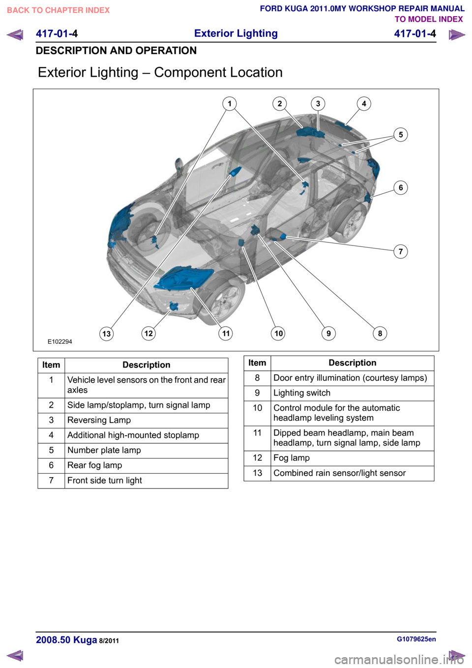
Exterior Lighting – Component Location
Description
Item
Vehicle level sensors on the front and rear
axles
1
Side lamp/stoplamp, turn signal lamp
2
Reversing Lamp
3
Additional high-mounted stoplamp
4
Number plate lamp
5
Rear fog lamp
6
Front side turn light
7 Description
Item
Door entry illumination (courtesy lamps)
8
Lighting switch
9
Control module for the automatic
headlamp leveling system
10
Dipped beam headlamp, main beam
headlamp, turn signal lamp, side lamp
11
Fog lamp
12
Combined rain sensor/light sensor
13 G1079625en
2008.50 Kuga 8/2011 417-01-4
Exterior Lighting
417-01-4
DESCRIPTION AND OPERATIONTO MODEL INDEX
BACK TO CHAPTER INDEX
FORD KUGA 2011.0MY WORKSHOP REPAIR MANUALE10229412345678910111213
Page 342 of 2057
On some models, the door entry lamps are installed
in the external mirrors.
The door entry lamps should illuminate the ground
in the immediate vicinity of the front doors; they
are equipped with white bulbs, which are installed
in the underside of the mirror.
The door entry illumination is switched on when
one of the doors or the tailgate are opened, or if
an unlocking command is detected and the
following conditions are satisfied:
• Vehicle Ignition is off.
• Reverse gear is not engaged.
• The vehicle speed is below 7 km/h.
The door entry illumination is switched off if one of
the following conditions is satisfied:
• The ignition is selected on.
• Reverse gear is engaged.
• The vehicle speed exceeds 7 km/h.
• More than 25 seconds have elapsed since the
tailgate was closed or a central locking
command was determined.
• The time set for the battery protection function for the interior lighting has elapsed.
• More than 5 seconds have elapsed since the doors and the tailgate were closed.
• More than 5 seconds have elapsed since a central locking command was received and the
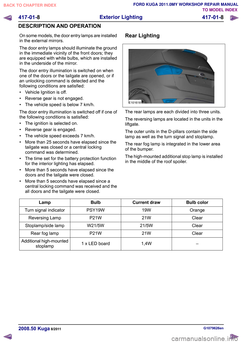
all doors and the tailgate were closed. Rear Lighting The rear lamps are each divided into three units.
The reversing lamps are located in the units in the
liftgate.
The outer units in the D-pillars contain the side
lamp as well as the turn signal and stoplamp.
The rear fog lamp is integrated in the lower area
of the bumper.
The high-mounted additional stop lamp is installed
in the middle of the roof spoiler.
Bulb color
Current draw
Bulb
Lamp
Orange
19W
PSY19W
Turn signal indicator
Clear
21W
P21W
Reversing Lamp
Clear
21/5W
W21/5W
Stoplamp/side lamp
Clear
21W
P21W
Rear fog lamp
–
1,4W
1 x LED board
Additional high-mounted
stoplamp G1079626en
2008.50 Kuga 8/2011 417-01-8
Exterior Lighting
417-01-8
DESCRIPTION AND OPERATIONTO MODEL INDEX
BACK TO CHAPTER INDEX
FORD KUGA 2011.0MY WORKSHOP REPAIR MANUALE101618
Page 346 of 2057
Fog Lamps
Refer to Wiring Diagrams Section 417-01, for
schematic and connector information.
Special Tool(s)
Terminal Probe Kit
29-011ADescription of operation
A diagnosis of the generic electronic module (GEM)
can be performed with the Ford approved
diagnostic tool. Furthermore, an integrated service
mode enables testing of the input and output
signals without the need for further tools. To enable
activation of service mode:
• switch off the ignition,
• switch off all other electrical consumers,
• apply the handbrake,
• shift to neutral
• and close the doors.
Activating the service mode
Proceed as follows to activate the service mode:
•
OPERATE the switch of the heated rear window
and HOLD IT THERE
• Turn on the ignition.
• RELEASE the switch of the heated rear window
A signal sounds and the turn signal lamps come
on to indicate that service mode has been
successfully activated.
NOTE: If the alarm is activated (in vehicles fitted
with an anti-theft alarm system), service mode
cannot be activated.
Inputs
SWITCH the windshield wiper switch to the "Off"
position to test the input signals. The following is
a list of the switch signals to be tested, in no
particular order:
• Turn signals (right, left, hazard warning lights)
• Windshield wiper stage I
• Windshield wiper stage II
• Windshield washer system • Rear window wiper
• Rear window washer system
• Doors open/closed
• Remote control for central locking with double
locking
• Hood open/closed (in vehicles equipped with an anti-theft alarm system)
• Tailgate open/closed
• A/C request signal
• Heated windscreen (if fitted)
• Parking Brake
• Brake reservoir fluid level
• Speed control system
• Autolamps
• dipped beam
• main beam
• headlamp flasher
• Marker Lamps
• Reversing lamp
• Liftgate release
• Ignition switch, terminal 15 (turn key to 0 position, then turn key to II position.)
An acoustic signal sounds and the turn signal
lamps flash to indicate receipt of each input signal
by the generic electronic module.
Test the windshield wiper "intermittent mode" stage
input signal (only vehicles with adjustable
intermittent mode)
The windshield wiper switch must be switched to
"intermittent mode" in order to test the input signal.
The delay times of the input signals can then be
tested by operating the rotary switch. Each change
of the rotary switch position is indicated by an
acoustic signal and illumination of the turn signals.
Output signals
SWITCH the wiper switch to the "intermittent""
position to test the output signals. PRESSING the
heated rear window switch activates the output
signals in the following order:
a. Turn Indicator Left Hand
b. Turn Indicator Right Hand
c. main beam
d. dipped beam
e. Windshield wiper stage I
f. Windshield wiper stage II G1055006en
2008.50 Kuga 8/2011 417-01-12
Exterior Lighting
417-01-12
DIAGNOSIS AND TESTINGTO MODEL INDEX
BACK TO CHAPTER INDEX
FORD KUGA 2011.0MY WORKSHOP REPAIR MANUAL29011A
Page 349 of 2057
Headlamps
Refer to
Wiring Diagrams Section 417-1, for
schematic and connector information.
Description of operation
A diagnosis of the generic electronic module (GEM)
can be performed with the Ford approved
diagnostic tool. Furthermore, an integrated service
mode enables testing of the input and output
signals without the need for further tools. To enable
activation of service mode:
• switch off the ignition,
• switch off all other electrical consumers,
• apply the handbrake,
• shift to neutral
• and close the doors.
Activating the service mode
Proceed as follows to activate the service mode:
• OPERATE the switch of the heated rear window
and HOLD IT THERE
• Turn on the ignition.
• RELEASE the switch of the heated rear window
A signal sounds and the turn signal lamps come
on to indicate that service mode has been
successfully activated.
NOTE: If the alarm is activated (in vehicles fitted
with an anti-theft alarm system), service mode
cannot be activated.
Inputs
SWITCH the windshield wiper switch to the "Off"
position to test the input signals. The following is
a list of the switch signals to be tested, in no
particular order:
• Turn signals (right, left, hazard warning lights)
• Windshield wiper stage I
• Windshield wiper stage II
• Windshield washer system
• Rear window wiper
• Rear window washer system
• Doors open/closed
• Remote control for central locking with double locking
• Hood open/closed (in vehicles equipped with an anti-theft alarm system)
• Tailgate open/closed • A/C request signal
• Heated windscreen (if fitted)
• Parking Brake
• Brake reservoir fluid level
• Speed control system
• Autolamps
• dipped beam
• main beam
• headlamp flasher
• Marker Lamps
• Reversing lamp
• Liftgate release
• Ignition switch, terminal 15 (turn key to 0
position, then turn key to II position.)
An acoustic signal sounds and the turn signal
lamps flash to indicate receipt of each input signal
by the generic electronic module.
Test the windshield wiper "intermittent mode" stage
input signal (only vehicles with adjustable
intermittent mode)
The windshield wiper switch must be switched to
"intermittent mode" in order to test the input signal.
The delay times of the input signals can then be
tested by operating the rotary switch. Each change
of the rotary switch position is indicated by an
acoustic signal and illumination of the turn signals.
Output signals
SWITCH the wiper switch to the "intermittent""
position to test the output signals. PRESSING the
heated rear window switch activates the output
signals in the following order:
a. Turn Indicator Left Hand
b. Turn Indicator Right Hand
c. main beam
d. dipped beam
e. Windshield wiper stage I
f. Windshield wiper stage II
g. Heated rear window
h. Heater blower motor
i. Headlamp washer system (vehicles with gas discharge headlamps)
j. Electric booster heater (if fitted)
k. Autolamps (if fitted)
l. Alarm horn (vehicles with alarm system) G1056684en
2008.50 Kuga 8/2011 417-01-15
Exterior Lighting
417-01-15
DIAGNOSIS AND TESTINGTO MODEL INDEX
BACK TO CHAPTER INDEX
FORD KUGA 2011.0MY WORKSHOP REPAIR MANUAL
Page 351 of 2057
Headlamp Leveling
Refer to Wiring Diagrams Section 417-01, for
schematic and connector information.
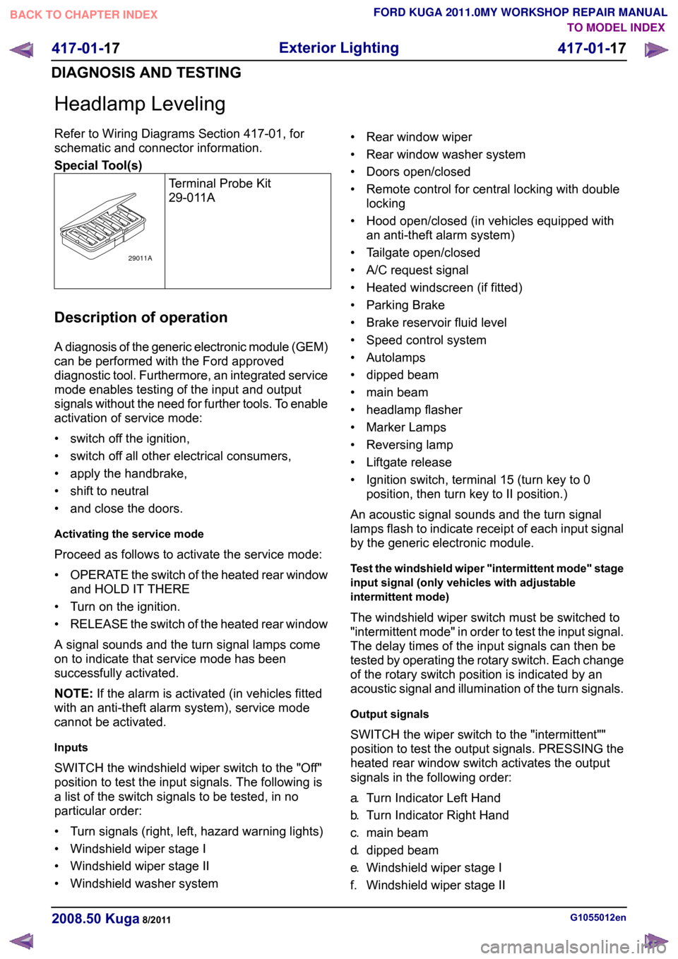
Special Tool(s)
Terminal Probe Kit
29-011ADescription of operation
A diagnosis of the generic electronic module (GEM)
can be performed with the Ford approved
diagnostic tool. Furthermore, an integrated service
mode enables testing of the input and output
signals without the need for further tools. To enable
activation of service mode:
• switch off the ignition,
• switch off all other electrical consumers,
• apply the handbrake,
• shift to neutral
• and close the doors.
Activating the service mode
Proceed as follows to activate the service mode:
•
OPERATE the switch of the heated rear window
and HOLD IT THERE
• Turn on the ignition.
• RELEASE the switch of the heated rear window
A signal sounds and the turn signal lamps come
on to indicate that service mode has been
successfully activated.
NOTE: If the alarm is activated (in vehicles fitted
with an anti-theft alarm system), service mode
cannot be activated.
Inputs
SWITCH the windshield wiper switch to the "Off"
position to test the input signals. The following is
a list of the switch signals to be tested, in no
particular order:
• Turn signals (right, left, hazard warning lights)
• Windshield wiper stage I
• Windshield wiper stage II
• Windshield washer system • Rear window wiper
• Rear window washer system
• Doors open/closed
• Remote control for central locking with double
locking
• Hood open/closed (in vehicles equipped with an anti-theft alarm system)
• Tailgate open/closed
• A/C request signal
• Heated windscreen (if fitted)
• Parking Brake
• Brake reservoir fluid level
• Speed control system
• Autolamps
• dipped beam
• main beam
• headlamp flasher
• Marker Lamps
• Reversing lamp
• Liftgate release
• Ignition switch, terminal 15 (turn key to 0 position, then turn key to II position.)
An acoustic signal sounds and the turn signal
lamps flash to indicate receipt of each input signal
by the generic electronic module.
Test the windshield wiper "intermittent mode" stage
input signal (only vehicles with adjustable
intermittent mode)
The windshield wiper switch must be switched to
"intermittent mode" in order to test the input signal.
The delay times of the input signals can then be
tested by operating the rotary switch. Each change
of the rotary switch position is indicated by an
acoustic signal and illumination of the turn signals.
Output signals
SWITCH the wiper switch to the "intermittent""
position to test the output signals. PRESSING the
heated rear window switch activates the output
signals in the following order:
a. Turn Indicator Left Hand
b. Turn Indicator Right Hand
c. main beam
d. dipped beam
e. Windshield wiper stage I
f. Windshield wiper stage II G1055012en
2008.50 Kuga 8/2011 417-01-17
Exterior Lighting
417-01-17
DIAGNOSIS AND TESTINGTO MODEL INDEX
BACK TO CHAPTER INDEX
FORD KUGA 2011.0MY WORKSHOP REPAIR MANUAL29011A
Page 353 of 2057
Parking, Rear and License Plate Lamps
Refer to Wiring Diagrams Section 417-01, for
schematic and connector information.
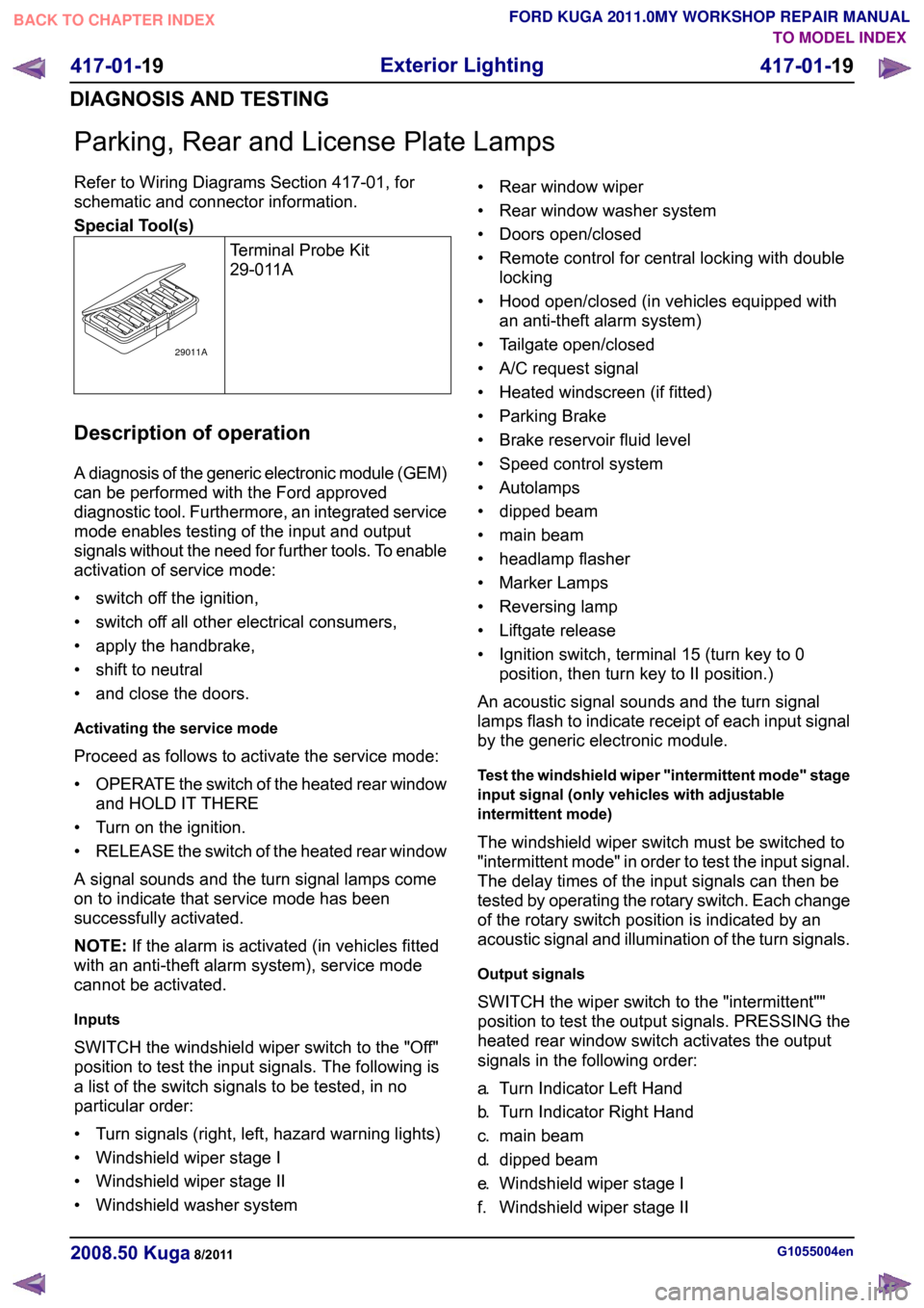
Special Tool(s)
Terminal Probe Kit
29-011ADescription of operation
A diagnosis of the generic electronic module (GEM)
can be performed with the Ford approved
diagnostic tool. Furthermore, an integrated service
mode enables testing of the input and output
signals without the need for further tools. To enable
activation of service mode:
• switch off the ignition,
• switch off all other electrical consumers,
• apply the handbrake,
• shift to neutral
• and close the doors.
Activating the service mode
Proceed as follows to activate the service mode:
•
OPERATE the switch of the heated rear window
and HOLD IT THERE
• Turn on the ignition.
• RELEASE the switch of the heated rear window
A signal sounds and the turn signal lamps come
on to indicate that service mode has been
successfully activated.
NOTE: If the alarm is activated (in vehicles fitted
with an anti-theft alarm system), service mode
cannot be activated.
Inputs
SWITCH the windshield wiper switch to the "Off"
position to test the input signals. The following is
a list of the switch signals to be tested, in no
particular order:
• Turn signals (right, left, hazard warning lights)
• Windshield wiper stage I
• Windshield wiper stage II
• Windshield washer system • Rear window wiper
• Rear window washer system
• Doors open/closed
• Remote control for central locking with double
locking
• Hood open/closed (in vehicles equipped with an anti-theft alarm system)
• Tailgate open/closed
• A/C request signal
• Heated windscreen (if fitted)
• Parking Brake
• Brake reservoir fluid level
• Speed control system
• Autolamps
• dipped beam
• main beam
• headlamp flasher
• Marker Lamps
• Reversing lamp
• Liftgate release
• Ignition switch, terminal 15 (turn key to 0 position, then turn key to II position.)
An acoustic signal sounds and the turn signal
lamps flash to indicate receipt of each input signal
by the generic electronic module.
Test the windshield wiper "intermittent mode" stage
input signal (only vehicles with adjustable
intermittent mode)
The windshield wiper switch must be switched to
"intermittent mode" in order to test the input signal.
The delay times of the input signals can then be
tested by operating the rotary switch. Each change
of the rotary switch position is indicated by an
acoustic signal and illumination of the turn signals.
Output signals
SWITCH the wiper switch to the "intermittent""
position to test the output signals. PRESSING the
heated rear window switch activates the output
signals in the following order:
a. Turn Indicator Left Hand
b. Turn Indicator Right Hand
c. main beam
d. dipped beam
e. Windshield wiper stage I
f. Windshield wiper stage II G1055004en
2008.50 Kuga 8/2011 417-01-19
Exterior Lighting
417-01-19
DIAGNOSIS AND TESTINGTO MODEL INDEX
BACK TO CHAPTER INDEX
FORD KUGA 2011.0MY WORKSHOP REPAIR MANUAL29011A
Page 355 of 2057
Reversing Lamps
Refer to Wiring Diagrams Section 417-01, for
schematic and connector information.
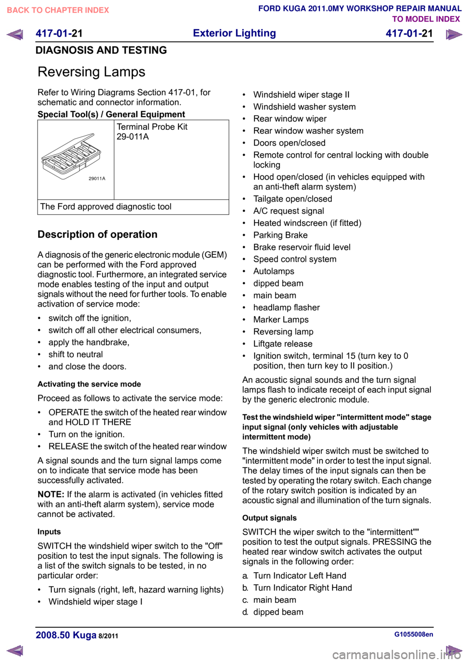
Special Tool(s) / General Equipment
Terminal Probe Kit
29-011AThe Ford approved diagnostic tool
Description of operation
A diagnosis of the generic electronic module (GEM)
can be performed with the Ford approved
diagnostic tool. Furthermore, an integrated service
mode enables testing of the input and output
signals without the need for further tools. To enable
activation of service mode:
• switch off the ignition,
• switch off all other electrical consumers,
• apply the handbrake,
• shift to neutral
• and close the doors.
Activating the service mode
Proceed as follows to activate the service mode:
• OPERATE the switch of the heated rear window
and HOLD IT THERE
• Turn on the ignition.
• RELEASE the switch of the heated rear window
A signal sounds and the turn signal lamps come
on to indicate that service mode has been
successfully activated.
NOTE: If the alarm is activated (in vehicles fitted
with an anti-theft alarm system), service mode
cannot be activated.
Inputs
SWITCH the windshield wiper switch to the "Off"
position to test the input signals. The following is
a list of the switch signals to be tested, in no
particular order:
• Turn signals (right, left, hazard warning lights)
• Windshield wiper stage I • Windshield wiper stage II
• Windshield washer system
• Rear window wiper
• Rear window washer system
• Doors open/closed
• Remote control for central locking with double
locking
• Hood open/closed (in vehicles equipped with an anti-theft alarm system)
• Tailgate open/closed
• A/C request signal
• Heated windscreen (if fitted)
• Parking Brake
• Brake reservoir fluid level
• Speed control system
• Autolamps
• dipped beam
• main beam
• headlamp flasher
• Marker Lamps
• Reversing lamp
• Liftgate release
• Ignition switch, terminal 15 (turn key to 0 position, then turn key to II position.)
An acoustic signal sounds and the turn signal
lamps flash to indicate receipt of each input signal
by the generic electronic module.
Test the windshield wiper "intermittent mode" stage
input signal (only vehicles with adjustable
intermittent mode)
The windshield wiper switch must be switched to
"intermittent mode" in order to test the input signal.
The delay times of the input signals can then be
tested by operating the rotary switch. Each change
of the rotary switch position is indicated by an
acoustic signal and illumination of the turn signals.
Output signals
SWITCH the wiper switch to the "intermittent""
position to test the output signals. PRESSING the
heated rear window switch activates the output
signals in the following order:
a. Turn Indicator Left Hand
b. Turn Indicator Right Hand
c. main beam
d. dipped beam G1055008en
2008.50 Kuga 8/2011 417-01-21
Exterior Lighting
417-01-21
DIAGNOSIS AND TESTINGTO MODEL INDEX
BACK TO CHAPTER INDEX
FORD KUGA 2011.0MY WORKSHOP REPAIR MANUAL29011A
Page 358 of 2057
Stoplamps
Description of operation
A diagnosis of the generic electronic module (GEM)
can be performed with the Ford approved
diagnostic tool. Furthermore, an integrated service
mode enables testing of the input and output
signals without the need for further tools. To enable
activation of service mode:
• switch off the ignition,
• switch off all other electrical consumers,
• apply the handbrake,
• shift to neutral
• and close the doors.
Activating the service mode
Proceed as follows to activate the service mode:
•
OPERATE the switch of the heated rear window
and HOLD IT THERE
• Turn on the ignition.
• RELEASE the switch of the heated rear window
A signal sounds and the turn signal lamps come
on to indicate that service mode has been
successfully activated.
NOTE: If the alarm is activated (in vehicles fitted
with an anti-theft alarm system), service mode
cannot be activated.
Inputs
SWITCH the windshield wiper switch to the "Off"
position to test the input signals. The following is
a list of the switch signals to be tested, in no
particular order:
• Turn signals (right, left, hazard warning lights)
• Windshield wiper stage I
• Windshield wiper stage II
• Windshield washer system
• Rear window wiper
• Rear window washer system
• Doors open/closed
• Remote control for central locking with double locking
• Hood open/closed (in vehicles equipped with an anti-theft alarm system)
• Tailgate open/closed
• A/C request signal
• Heated windscreen (if fitted) • Parking Brake
• Brake reservoir fluid level
• Speed control system
• Autolamps
• dipped beam
• main beam
• headlamp flasher
• Marker Lamps
• Reversing lamp
• Liftgate release
• Ignition switch, terminal 15 (turn key to 0
position, then turn key to II position.)
An acoustic signal sounds and the turn signal
lamps flash to indicate receipt of each input signal
by the generic electronic module.
Test the windshield wiper "intermittent mode" stage
input signal (only vehicles with adjustable
intermittent mode)
The windshield wiper switch must be switched to
"intermittent mode" in order to test the input signal.
The delay times of the input signals can then be
tested by operating the rotary switch. Each change
of the rotary switch position is indicated by an
acoustic signal and illumination of the turn signals.
Output signals
SWITCH the wiper switch to the "intermittent""
position to test the output signals. PRESSING the
heated rear window switch activates the output
signals in the following order:
a. Turn Indicator Left Hand
b. Turn Indicator Right Hand
c. main beam
d. dipped beam
e. Windshield wiper stage I
f. Windshield wiper stage II
g. Heated rear window
h. Heater blower motor
i. Headlamp washer system (vehicles with gas discharge headlamps)
j. Electric booster heater (if fitted)
k. Autolamps (if fitted)
l. Alarm horn (vehicles with alarm system)
m. Rear window wiper
n. Rear heated window relay G1056685en
2008.50 Kuga 8/2011 417-01-24
Exterior Lighting
417-01-24
DIAGNOSIS AND TESTINGTO MODEL INDEX
BACK TO CHAPTER INDEX
FORD KUGA 2011.0MY WORKSHOP REPAIR MANUAL
Page 360 of 2057
Turn Signal and Hazard Lamps
Refer to Wiring Diagrams Section 417-01, for
schematic and connector information.
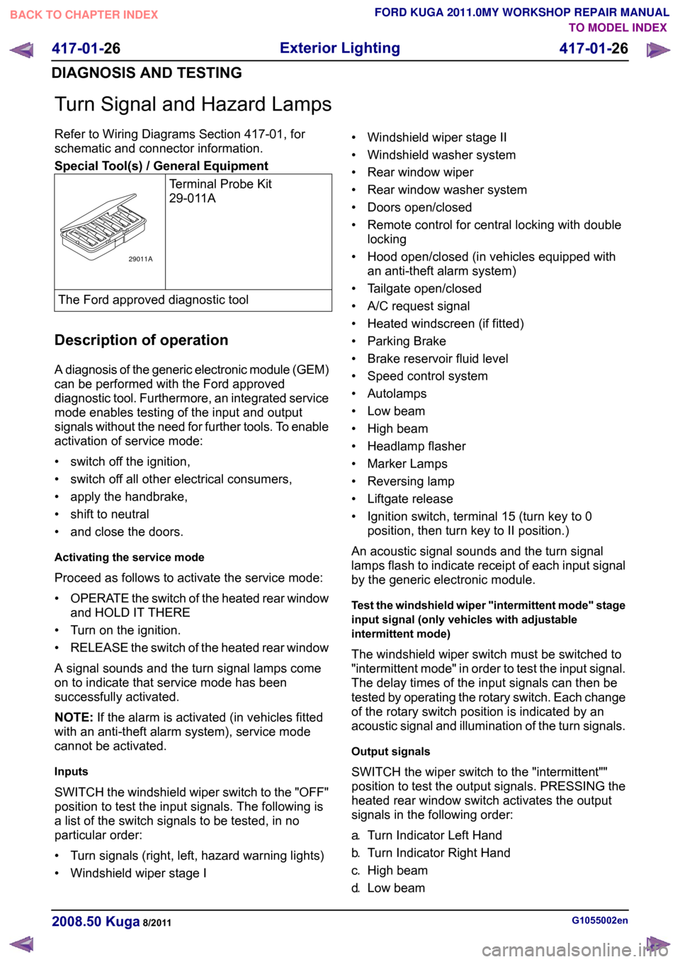
Special Tool(s) / General Equipment
Terminal Probe Kit
29-011AThe Ford approved diagnostic tool
Description of operation
A diagnosis of the generic electronic module (GEM)
can be performed with the Ford approved
diagnostic tool. Furthermore, an integrated service
mode enables testing of the input and output
signals without the need for further tools. To enable
activation of service mode:
• switch off the ignition,
• switch off all other electrical consumers,
• apply the handbrake,
• shift to neutral
• and close the doors.
Activating the service mode
Proceed as follows to activate the service mode:
• OPERATE the switch of the heated rear window
and HOLD IT THERE
• Turn on the ignition.
• RELEASE the switch of the heated rear window
A signal sounds and the turn signal lamps come
on to indicate that service mode has been
successfully activated.
NOTE: If the alarm is activated (in vehicles fitted
with an anti-theft alarm system), service mode
cannot be activated.
Inputs
SWITCH the windshield wiper switch to the "OFF"
position to test the input signals. The following is
a list of the switch signals to be tested, in no
particular order:
• Turn signals (right, left, hazard warning lights)
• Windshield wiper stage I • Windshield wiper stage II
• Windshield washer system
• Rear window wiper
• Rear window washer system
• Doors open/closed
• Remote control for central locking with double
locking
• Hood open/closed (in vehicles equipped with an anti-theft alarm system)
• Tailgate open/closed
• A/C request signal
• Heated windscreen (if fitted)
• Parking Brake
• Brake reservoir fluid level
• Speed control system
• Autolamps
• Low beam
• High beam
• Headlamp flasher
• Marker Lamps
• Reversing lamp
• Liftgate release
• Ignition switch, terminal 15 (turn key to 0 position, then turn key to II position.)
An acoustic signal sounds and the turn signal
lamps flash to indicate receipt of each input signal
by the generic electronic module.
Test the windshield wiper "intermittent mode" stage
input signal (only vehicles with adjustable
intermittent mode)
The windshield wiper switch must be switched to
"intermittent mode" in order to test the input signal.
The delay times of the input signals can then be
tested by operating the rotary switch. Each change
of the rotary switch position is indicated by an
acoustic signal and illumination of the turn signals.
Output signals
SWITCH the wiper switch to the "intermittent""
position to test the output signals. PRESSING the
heated rear window switch activates the output
signals in the following order:
a. Turn Indicator Left Hand
b. Turn Indicator Right Hand
c. High beam
d. Low beam G1055002en
2008.50 Kuga 8/2011 417-01-26
Exterior Lighting
417-01-26
DIAGNOSIS AND TESTINGTO MODEL INDEX
BACK TO CHAPTER INDEX
FORD KUGA 2011.0MY WORKSHOP REPAIR MANUAL29011A