service indicator FORD KUGA 2011 1.G User Guide
[x] Cancel search | Manufacturer: FORD, Model Year: 2011, Model line: KUGA, Model: FORD KUGA 2011 1.GPages: 2057
Page 1355 of 2057

too close to the fluid level indicator assembly,
or float assembly damage.
Bypass Condition Test
1. Check the fluid in the brake master cylinderreservoir. Fill the brake master cylinder reservoir
if low or empty.
2. Observe the fluid level in the brake master cylinder reservoir. If after several brake
applications, the fluid level remains the same,
measure the wheel turning torque required to
rotate the wheels with the brakes applied as
follows:
Place the transaxle in the NEUTRAL position.
Raise and support the vehicle. REFER to: (100-02
Jacking and Lifting) Jacking (Description and Operation),
Lifting (Description and Operation).
Apply the brakes with a minimum of 445 N (100
lb) and hold for approximately 15 seconds. With
the brakes still applied, exert a torque on the front
wheels of 10.1 Nm (75 lb ft). If either wheel rotates,
install a new brake master cylinder.
REFER to: Brake Master Cylinder - 2.5L Duratec
(147kW/200PS) - VI5 (206-06 Hydraulic Brake
Actuation, Removal and Installation).
Non-Pressure Leaks
Any empty brake master cylinder reservoir
condition may be caused by two types of
non-pressure external leaks.
Type 1: An external leak may occur at the brake
master cylinder reservoir cap because of incorrect
positioning of the gasket and cap. Reposition the
cap and gasket.
Type 2: An external leak may occur at the brake
master cylinder reservoir mounting seals. Service
such a leak by installing new seals.
G1058975en2008.50 Kuga8/2011
206-00- 19
Brake System - General Information
206-00- 19
DIAGNOSIS AND TESTING
TO MODEL INDEX
BACK TO CHAPTER INDEX
FORD KUGA 2011.0MY WORKSHOP REPAIR MANUAL
Page 1986 of 2057

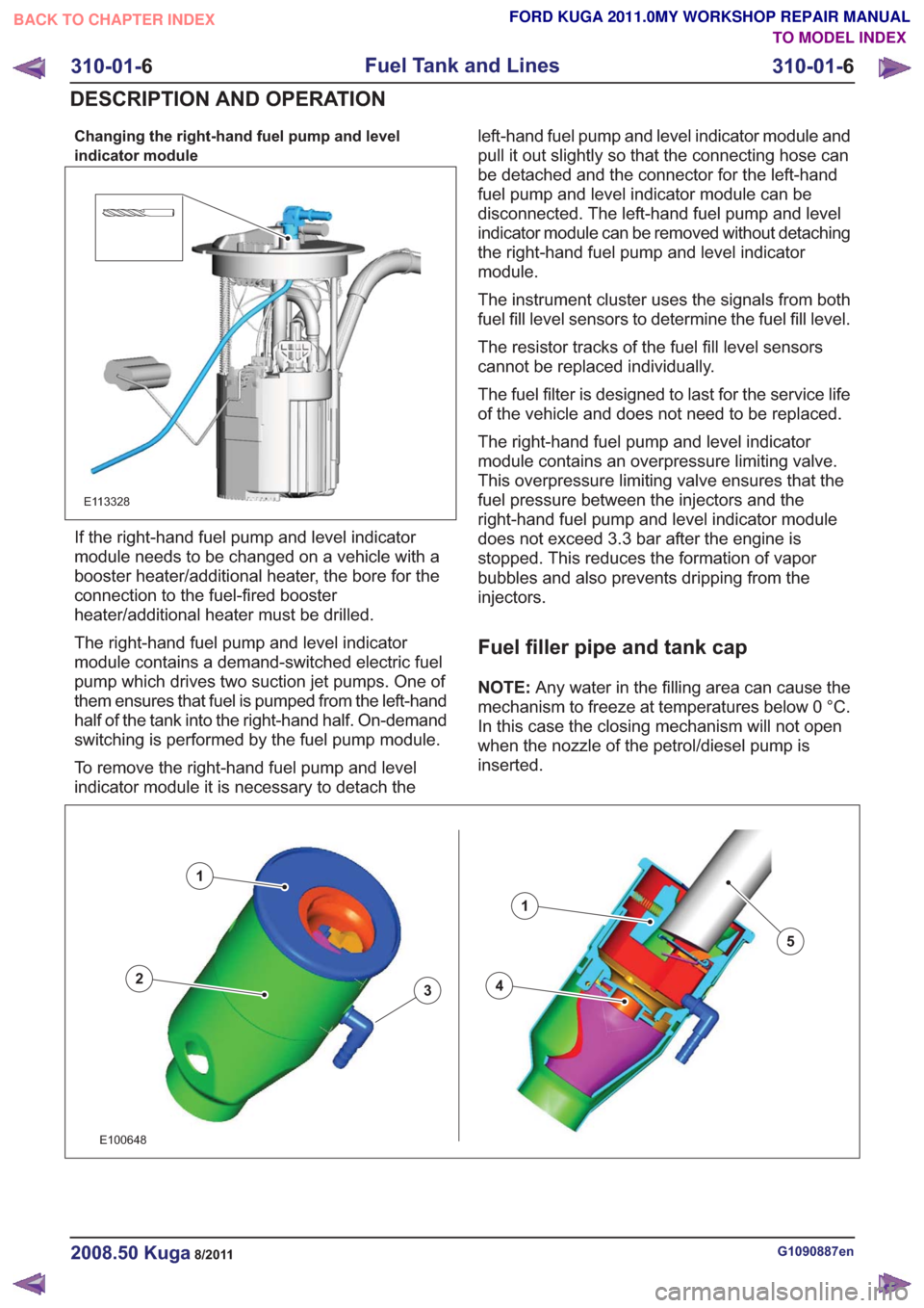
Changing the right-hand fuel pump and level
indicator module
E113328
If the right-hand fuel pump and level indicator
module needs to be changed on a vehicle with a
booster heater/additional heater, the bore for the
connection to the fuel-fired booster
heater/additional heater must be drilled.
The right-hand fuel pump and level indicator
module contains a demand-switched electric fuel
pump which drives two suction jet pumps. One of
them ensures that fuel is pumped from the left-hand
half of the tank into the right-hand half. On-demand
switching is performed by the fuel pump module.
To remove the right-hand fuel pump and level
indicator module it is necessary to detach theleft-hand fuel pump and level indicator module and
pull it out slightly so that the connecting hose can
be detached and the connector for the left-hand
fuel pump and level indicator module can be
disconnected. The left-hand fuel pump and level
indicator module can be removed without detaching
the right-hand fuel pump and level indicator
module.
The instrument cluster uses the signals from both
fuel fill level sensors to determine the fuel fill level.
The resistor tracks of the fuel fill level sensors
cannot be replaced individually.
The fuel filter is designed to last for the service life
of the vehicle and does not need to be replaced.
The right-hand fuel pump and level indicator
module contains an overpressure limiting valve.
This overpressure limiting valve ensures that the
fuel pressure between the injectors and the
right-hand fuel pump and level indicator module
does not exceed 3.3 bar after the engine is
stopped. This reduces the formation of vapor
bubbles and also prevents dripping from the
injectors.
Fuel filler pipe and tank cap
NOTE:
Any water in the filling area can cause the
mechanism to freeze at temperatures below 0 °C.
In this case the closing mechanism will not open
when the nozzle of the petrol/diesel pump is
inserted.
43
1
2
1
5
43
1
2
1
5
E100648
G1090887en2008.50 Kuga8/2011
310-01- 6
Fuel Tank and Lines
310-01- 6
DESCRIPTION AND OPERATION
TO MODEL INDEX
BACK TO CHAPTER INDEX
FORD KUGA 2011.0MY WORKSHOP REPAIR MANUAL