ELECTRICAL FORD KUGA 2011 1.G Owner's Manual
[x] Cancel search | Manufacturer: FORD, Model Year: 2011, Model line: KUGA, Model: FORD KUGA 2011 1.GPages: 2057
Page 264 of 2057
2. Switch the multimeter to the voltage function.
3. Connect the leads of the multimeter across the
battery terminals.
4. Read the voltage (base voltage).
5. Start the engine.
6. Run the engine at 1500 rpm with no electrical load.
7. Read the voltage. The voltage should be in the range of 14.1 volts to 15.1 volts. If the voltage
increase is less than 2.5 volts above the base
voltage, carry out the Load Test. If the voltage
increase is greater than 2.5 volts, REFER to the
Ford diagnostic equipment. Generator On-Vehicle Tests - Load Test
1. With the engine running, turn on the air
conditioning (if equipped), turn the blower motor
to high speed and the headlamps to high beam.
2. Increase the engine speed to 2000 rpm. The voltage should increase a minimum of 0.5 volts
above the base voltage. If the voltage does not
increase as specified, REFER to the Ford
approved diagnostic tool. If the voltage
increases as specified, the charging system is
charging correctly.
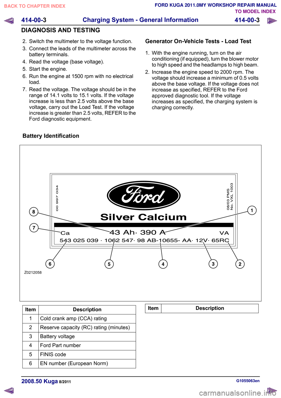
Battery Identification Description
Item
Cold crank amp (CCA) rating
1
Reserve capacity (RC) rating (minutes)
2
Battery voltage
3
Ford Part number
4
FINIS code
5
EN number (European Norm)
6 Description
Item G1055063en
2008.50 Kuga 8/2011 414-00-3
Charging System - General Information
414-00-3
DIAGNOSIS AND TESTINGTO MODEL INDEX
BACK TO CHAPTER INDEX
FORD KUGA 2011.0MY WORKSHOP REPAIR MANUALZ0212058
Page 267 of 2057
Action
Battery Tester Reading WARNING: Do not recharge the battery.
Make sure that the surface charge was removed. A "REPLACE BATTERY" result could also mean
a poor connection between the battery cables and the battery. Check the connections are OK and
retest. If the result remains the same, INSTALL a NEW battery
REFER to: Battery(414-01 Battery, Mounting and
Cables, Removal and Installation).
REPLACE BATTERY or BAD CELL BATTERY
In addition it is advisable to check the vehicle electrical system. Check that the generator is functioning
correctly and the vehicle does not have an excessive key-off load (in general this should be under
20mA after 40 minutes of key off).
Midtronics EXP-1050 Battery Tester Test
Code
At the end of the test, use the arrow keys to scroll
down the screens to see additional information.
One of these is the TEST CODE.
The TEST CODE has 11 digits, for example:
0021U-B88WKX.
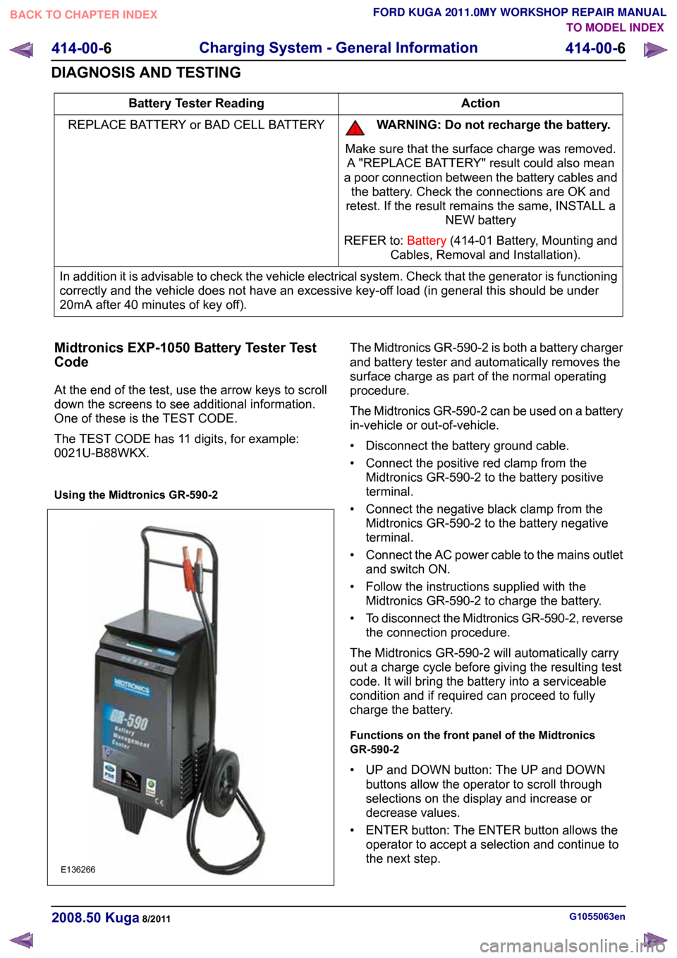
Using the Midtronics GR-590-2 The Midtronics GR-590-2 is both a battery charger
and battery tester and automatically removes the
surface charge as part of the normal operating
procedure.
The Midtronics GR-590-2 can be used on a battery
in-vehicle or out-of-vehicle.
• Disconnect the battery ground cable.
• Connect the positive red clamp from the
Midtronics GR-590-2 to the battery positive
terminal.
• Connect the negative black clamp from the Midtronics GR-590-2 to the battery negative
terminal.
• Connect the AC power cable to the mains outlet
and switch ON.
• Follow the instructions supplied with the Midtronics GR-590-2 to charge the battery.
• To disconnect the Midtronics GR-590-2, reverse
the connection procedure.
The Midtronics GR-590-2 will automatically carry
out a charge cycle before giving the resulting test
code. It will bring the battery into a serviceable
condition and if required can proceed to fully
charge the battery.
Functions on the front panel of the Midtronics
GR-590-2
• UP and DOWN button: The UP and DOWN buttons allow the operator to scroll through
selections on the display and increase or
decrease values.
• ENTER button: The ENTER button allows the operator to accept a selection and continue to
the next step. G1055063en
2008.50 Kuga 8/2011 414-00-6
Charging System - General Information
414-00-6
DIAGNOSIS AND TESTINGTO MODEL INDEX
BACK TO CHAPTER INDEX
FORD KUGA 2011.0MY WORKSHOP REPAIR MANUALE136266
Page 270 of 2057
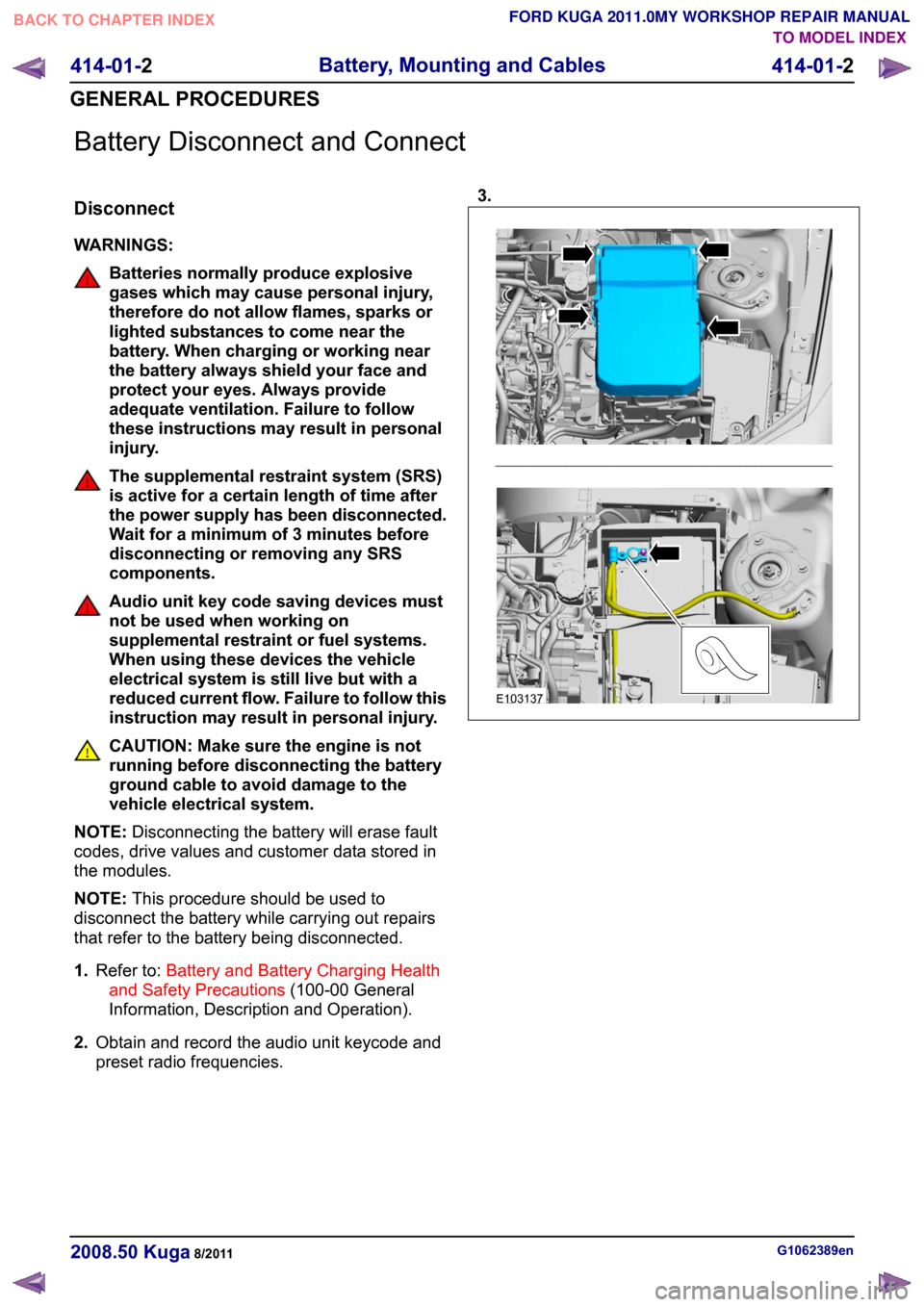
Battery Disconnect and Connect
Disconnect
WARNINGS:
Batteries normally produce explosive
gases which may cause personal injury,
therefore do not allow flames, sparks or
lighted substances to come near the
battery. When charging or working near
the battery always shield your face and
protect your eyes. Always provide
adequate ventilation. Failure to follow
these instructions may result in personal
injury.
The supplemental restraint system (SRS)
is active for a certain length of time after
the power supply has been disconnected.
Wait for a minimum of 3 minutes before
disconnecting or removing any SRS
components.
Audio unit key code saving devices must
not be used when working on
supplemental restraint or fuel systems.
When using these devices the vehicle
electrical system is still live but with a
reduced current flow. Failure to follow this
instruction may result in personal injury.
CAUTION: Make sure the engine is not
running before disconnecting the battery
ground cable to avoid damage to the
vehicle electrical system.
NOTE: Disconnecting the battery will erase fault
codes, drive values and customer data stored in
the modules.
NOTE: This procedure should be used to
disconnect the battery while carrying out repairs
that refer to the battery being disconnected.
1. Refer to: Battery and Battery Charging Health
and Safety Precautions (100-00 General
Information, Description and Operation).
2. Obtain and record the audio unit keycode and
preset radio frequencies. 3.
G1062389en
2008.50 Kuga 8/2011 414-01-2
Battery, Mounting and Cables
414-01-2
GENERAL PROCEDURESTO MODEL INDEX
BACK TO CHAPTER INDEX
FORD KUGA 2011.0MY WORKSHOP REPAIR MANUALE103137
Page 274 of 2057

Generator
General information
The powertrain control module (PCM) controls the
alternator charging voltage. The connection
between the PCM and the generator is made via
the control module subnetwork (LIN) bus.
If the load on the alternator is high, the PCM can
increase the idle speed.
The alternator is temporarily deactivated during
engine starting so that the engine drag moment is
minimized and it is reactivated again after the
starting procedure.
The PCM controls the charge control lamp in the
instrument cluster via the controller area network
(CAN) bus.
Smart Charge system
In addition to the familiar functions, the Smart
Charge system also performs the following
functions:
•
Automatic deactivation of non-critical high power
electrical consumers when the battery voltage
is low in order to reduce the level of current
drawn.
• Automatic activation of non-critical high power electrical consumers when the battery voltage
is excessively high in order to protect
components which are sensitive to increased
voltages.
The battery charging current is optimized through
continuous calculation of the battery temperature
and monitoring of the alternator output voltage.
By receiving the forwarded alternator load signal,
the PCM is given early warning whenever an
electric consumer is switched on or off. This means
that the PCM receives information about imminent
changes in the torque drawn by the alternator. By
evaluating this information the PCM can provide a
higher level of idling stability.
The two remaining functions of the Smart Charge
System are controlled by the GEM.
Electrical consumers are switched off due to low
voltage when the GEM determines (on the basis
of the message received from the PCM on the CAN
bus via the instrument cluster) that the battery
voltage has dropped below the threshold.
When the threshold for low battery voltage is
reached the GEM automatically deactivates the following consumers - in this order and with a gap
of 5 seconds between each:
• Electric booster heater (vehicles with diesel
engines)
• Heated exterior mirrors
• Heated rear window
• Heated windscreen
If the battery voltage rises back above the lower
threshold then the GEM re-enables all of the
electrical consumers which were previously
disabled. They then have switched off status and
must be switched back on by the driver.
Electrical consumers are switched on due to
excessively high voltage if the GEM determines
that the battery voltage is above the threshold for
overvoltage and the charge control lamp has been
switched on.
When the threshold is reached the GEM
automatically activates the following consumers -
in this order and with a gap of 5 seconds between
each:
• Heated rear window
• Heated exterior mirrors
• Electric booster heater (vehicles with diesel engines)
• Blower motor
If the battery voltage drops back below the
threshold then the GEM automatically deactivates
any consumers that were switched on. However,
if they were switched on by the driver before the
automatic activation, they will then be switched on
again in turn with a 5-second time interval. G964174en
2008.50 Kuga 8/2011 414-02-2
Generator and Regulator
414-02-2
DESCRIPTION AND OPERATIONTO MODEL INDEX
BACK TO CHAPTER INDEX
FORD KUGA 2011.0MY WORKSHOP REPAIR MANUAL
Page 280 of 2057
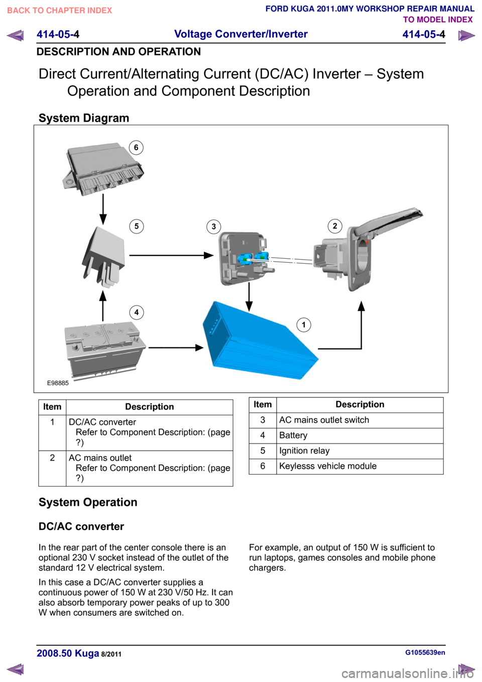
Direct Current/Alternating Current (DC/AC) Inverter – System
Operation and Component Description
System Diagram Description
Item
DC/AC converterRefer to Component Description: (page
?)
1
AC mains outletRefer to Component Description: (page
?)
2 Description
Item
AC mains outlet switch
3
Battery
4
Ignition relay
5
Keylesss vehicle module
6
System Operation
DC/AC converter
In the rear part of the center console there is an
optional 230 V socket instead of the outlet of the
standard 12 V electrical system.
In this case a DC/AC converter supplies a
continuous power of 150 W at 230 V/50 Hz. It can
also absorb temporary power peaks of up to 300
W when consumers are switched on. For example, an output of 150 W is sufficient to
run laptops, games consoles and mobile phone
chargers.
G1055639en
2008.50 Kuga 8/2011 414-05-4
Voltage Converter/Inverter
414-05-4
DESCRIPTION AND OPERATIONTO MODEL INDEX
BACK TO CHAPTER INDEX
FORD KUGA 2011.0MY WORKSHOP REPAIR MANUAL12456E988853
Page 281 of 2057
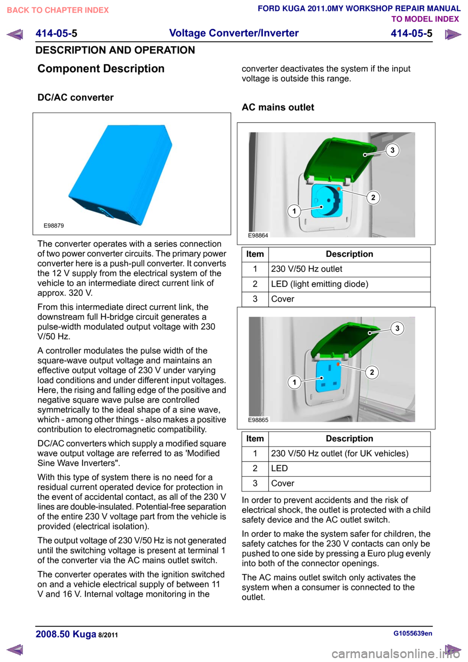
Component Description
DC/AC converter
The converter operates with a series connection
of two power converter circuits. The primary power
converter here is a push-pull converter. It converts
the 12 V supply from the electrical system of the
vehicle to an intermediate direct current link of
approx. 320 V.
From this intermediate direct current link, the
downstream full H-bridge circuit generates a
pulse-width modulated output voltage with 230
V/50 Hz.
A controller modulates the pulse width of the
square-wave output voltage and maintains an
effective output voltage of 230 V under varying
load conditions and under different input voltages.
Here, the rising and falling edge of the positive and
negative square wave pulse are controlled
symmetrically to the ideal shape of a sine wave,
which - among other things - also makes a positive
contribution to electromagnetic compatibility.
DC/AC converters which supply a modified square
wave output voltage are referred to as 'Modified
Sine Wave Inverters".
With this type of system there is no need for a
residual current operated device for protection in
the event of accidental contact, as all of the 230 V
lines are double-insulated. Potential-free separation
of the entire 230 V voltage part from the vehicle is
provided (electrical isolation).
The output voltage of 230 V/50 Hz is not generated
until the switching voltage is present at terminal 1
of the converter via the AC mains outlet switch.
The converter operates with the ignition switched
on and a vehicle electrical supply of between 11
V and 16 V. Internal voltage monitoring in the converter deactivates the system if the input
voltage is outside this range.
AC mains outlet
Description
Item
230 V/50 Hz outlet
1
LED (light emitting diode)
2
Cover3 Description
Item
230 V/50 Hz outlet (for UK vehicles)
1
LED2
Cover3
In order to prevent accidents and the risk of
electrical shock, the outlet is protected with a child
safety device and the AC outlet switch.
In order to make the system safer for children, the
safety catches for the 230 V contacts can only be
pushed to one side by pressing a Euro plug evenly
into both of the connector openings.
The AC mains outlet switch only activates the
system when a consumer is connected to the
outlet. G1055639en
2008.50 Kuga 8/2011 414-05-5
Voltage Converter/Inverter
414-05-5
DESCRIPTION AND OPERATIONTO MODEL INDEX
BACK TO CHAPTER INDEX
FORD KUGA 2011.0MY WORKSHOP REPAIR MANUALE98879 E98864312 E98865312
Page 288 of 2057

Audio System
Refer to Wiring Diagrams Section 415-01, for
schematic and connector information.
Refer to Wiring Diagrams Section 415-03, for
schematic and connector information.
General Equipment
The Ford approved diagnostic tool
Inspection and Verification
NOTE: If the keycode is entered incorrectly 3 times,
the system will allow the next keycode in 30
minutes. After entering the keycode the 10th time
incorrectly the system will lock out. The component
can only be unlocked by the manufacturer.
1. Verify the customer concern.
2. Visually inspect for obvious signs of mechanical
or electrical damage.
Visual Inspection Chart Electrical
Mechanical
– Fuse(s)
– Wiring harness
– Electricalconnector(s)
– Audio unit
– Audio control switch (if equipped)
– CD changer
– Central junction box (CJB)
– Audio unit
– Antenna
– Foreign objects
contacting speaker
– Trim poorly fitted/resonance
– Audio control switch (if equipped)
– Compact disc (CD) changer
3. If an obvious cause for an observed or reported concern is found, correct the cause (if possible)
before proceeding to the next step.
4. If the cause is not visually evident, verify the symptom and refer to the Self-Diagnostic Mode.
Self-Diagnostic Mode - Low Series
Audio Unit
NOTE: The audio unit must be in radio mode
before entering the Self-Diagnostic Mode.
1. To enter the audio unit Self-Diagnostic Mode, switch the audio unit ON. Within four seconds
depress the preset buttons 3 and 6 together.
2. Release the preset buttons 3 and 6 and the audio unit will enter the Self-Diagnostic Mode. 3.
The Self-Diagnostic Mode will automatically stop
after one iterration or to interrupt it , switch the
audio unit OFF.
Self-Diagnostic Mode Circuit Tested
Message Displayed
Right hand front woofercircuit
1. 4CH RF low
Right hand fronttweeter circuit.
2. 4CH RF high
Left hand front woofercircuit.
3. 4CH LF low
Left hand front tweetercircuit.
3. 4CH LF High
Right hand rear woofercircuit
1. 4CH RR low
Right hand rear tweetercircuit
2. 4CH RR high
Left hand rear woofercircuit
3. 4CH LR low
Left hand rear tweetercircuit.
3. 4CH LR High
Antenna connection
Seek 87.5 - 108.0
4. If the cause is not evident after the Self-Diagnostic Mode, connect the Ford
approved diagnostic tool to the data link
connector (DLC).
Self-Diagnostic Mode - High Series
Audio Unit GEN 2
NOTE: The audio unit must be in radio mode
before entering the Self-Diagnostic Mode.
1. To enter the audio unit Self-Diagnostic Mode, switch the audio unit ON. Within four seconds
depress the preset button 3 and 6 together.
2. Release the preset button 3 and 6 and the audio
unit will enter the Self-Diagnostic Mode.
3. The Self-Diagnostic Mode will automatically stop
after one iterration or to interrupt it , switch the
audio unit OFF.
Self-Diagnostic Mode Circuit Tested
Message Displayed
Right hand front woofercircuit
RF speaker 600Hz G1055068en
2008.50 Kuga 8/2011 415-00-2
Information and Entertainment System -
General Information
415-00-2
DIAGNOSIS AND TESTINGTO MODEL INDEX
BACK TO CHAPTER INDEX
FORD KUGA 2011.0MY WORKSHOP REPAIR MANUAL
Page 290 of 2057

Cellular Phone
Refer to
Wiring Diagrams Section 415-00, for
schematic and connector information. General Equipment
Ford diagnostic equipment
Principles of Operation
NOTE: Voice control will only operate with the
audio unit and components required switched ON.
Voice Control
The portable support electronics (PSE) module
has a voice control system. The customer will be
able to push the VOICE button on the audio control
switch located on the steering column lower
shroud, this will activate the PSE module and allow
voice control. An audible tone will be heard through
the audio unit speakers after which, a voice
command can then be spoken into the microphone
located in the overhead console.
The incoming calls and voice confirmation can be
heard through the audio system speakers.
When a voice command is spoken into the
microphone it will be sent as a signal to the PSE
module. The signal is then sent from the PSE
module to the relevant components on the
medium-speed controller area network (CAN) bus
network. The component will then convert the
signal back into the original voice command.
The components that the PSE module interacts
with are as follows:
• audio unit
• navigation system display module
• cellular phone
For additional information on the cellular phone
system, REFER to the cellular phone Owner's
Guide.
Bluetooth
An input can be given through the cellular phone
with or without the cellular phone connected to the
handset holder. Providing that the cellular phone
is one of the recommended cellular phones for the
system, is supplied with the Bluetooth technology
and the cellular phone is programmed to the PSE
module.
When selected as active the Bluetooth technology
is a wireless system that interacts with the relevant component modules through the PSE module. The
general operation of the Bluetooth is similar to the
voice control.
Bluetooth technology cannot transfer the cellular
phone's PHONEBOOK or recent outgoing and
incoming call details to the audio unit or navigation
system display module. If the cellular phone is
placed into the handset holder the PHONEBOOK
data and recent outgoing and incoming call
information will be transferred to the audio unit or
navigation system display module.
For additional information, REFER to the cellular
phone Owner's Guide.
Inspection and Verification
NOTE: Make sure that the cellular phone is
featured on the list of recommended cellular
phones for the system.
Make sure that the PSE module and cellular
phone are configured to each other before
starting a system diagnosis. ENTER the
following PIN number on the cellular phone to
configure the cellular phone to the PSE module:
0000.
Make sure that the MUTE symbol is not
displayed on the audio unit when trying to
operate the cellular phone system. If the MUTE
symbol is displayed, this indicates that the PSE
module requires configuring to the vehicle and
the cellular phone requires programming to the
PSE module. GO to
Pinpoint Test C.
1. Verify the customer concern by operating the system using the customers cellular phone.
2. Visually inspect for obvious signs of electrical damage.
Visual Inspection Chart Electrical
• Fuse(s)
• Wiring harness
• Electrical connector(s)
• Cellular phone
• Microphone
• PSE module
• Audio unit
• Instrument cluster
• Navigation system display module G1189085en
2008.50 Kuga 8/2011 415-00-4
Information and Entertainment System -
General Information
415-00-4
DIAGNOSIS AND TESTINGTO MODEL INDEX
BACK TO CHAPTER INDEX
FORD KUGA 2011.0MY WORKSHOP REPAIR MANUAL
Page 293 of 2057

Action
Possible Sources
Symptom
• CHECK all communicationbetween the audio unit and
PSE module. REFER to the
Ford diagnostic equipment.
• Audio unit.
• PSE module.
• Reduced sound or no sound
through the speakers
• REFER to the Ford diagnosticequipment.
• Circuit(s).
• Audio unit.
• PSE module.
• CHECK all communicationbetween the instrument cluster,
audio unit, navigation system
display module and PSE
module. REFER to the Ford
diagnostic equipment.
• Audio unit.
• Navigation system display
module.
• PSE module.
• Instrument cluster.
• The cellular phone information
is not displayed
• CHECK all communicationbetween the instrument cluster,
audio unit, navigation system
display module and PSE
module. REFER to the Ford
diagnostic equipment.
• Circuit(s).
• Cellular Phone.
• Audio unit.
• Navigation system display
module.
• PSE module.
• Instrument cluster.
• The voice activated phone
functions are inoperative
• CHECK the make and modelof the cellular phone against
those on the list of recom-
mended cellular phones for the
system.
• Cellular phone is not featured
on the list of recommended
cellular phones for the system
Pinpoint Tests
NOTE: ENTER the following PIN number on the
cellular phone to configure the cellular phone to
the PSE module: 0000. NOTE:
Use a digital multimeter for all electrical
measurements.
PINPOINT TEST A : NO COMMUNICATION WITH THE PORTABLE SUPPORT ELECTRONICS (PSE)
MODULE DETAILS/RESULTS/ACTIONS
TEST CONDITIONS
A1: CHECK FOR VOLTAGE AT THE PSE MODULE 1
Disconnect PSE Module C432. G1189085en
2008.50 Kuga 8/2011 415-00-7
Information and Entertainment System -
General Information
415-00-7
DIAGNOSIS AND TESTINGTO MODEL INDEX
BACK TO CHAPTER INDEX
FORD KUGA 2011.0MY WORKSHOP REPAIR MANUAL
Page 308 of 2057

Cellular Phone – Overview
Software update - control module for
mobile electronic auxiliary equipment
(variant 1)
There is a USB port near the central electrical
module. Software updates for the control module
for mobile electronic auxiliary equipment can be
carried out here.
Software update - control module for
mobile electronic auxiliary equipment
(variants 2 and 3)
Software updates for the mobile electronic auxiliary
equipment control module can be performed via
the USB port which is integrated into the center
console.
G1055657en
2008.50 Kuga 8/2011 415-01-12
Information and Entertainment System
415-01-12
DESCRIPTION AND OPERATIONTO MODEL INDEX
BACK TO CHAPTER INDEX
FORD KUGA 2011.0MY WORKSHOP REPAIR MANUAL