Locks FORD KUGA 2011 1.G Owner's Manual
[x] Cancel search | Manufacturer: FORD, Model Year: 2011, Model line: KUGA, Model: FORD KUGA 2011 1.GPages: 2057
Page 1856 of 2057
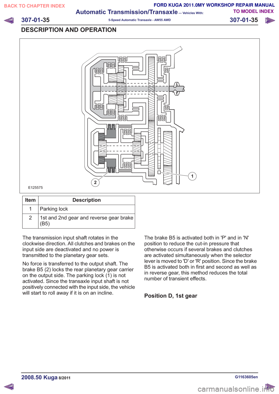
E125575
1
2
Description
Item
Parking lock
1
1st and 2nd gear and reverse gear brake
(B5)
2
The transmission input shaft rotates in the
clockwise direction. All clutches and brakes on the
input side are deactivated and no power is
transmitted to the planetary gear sets.
No force is transferred to the output shaft. The
brake B5 (2) locks the rear planetary gear carrier
on the output side. The parking lock (1) is not
activated. Since the transaxle input shaft is not
positively connected with the input side, the vehicle
will start to roll away if it is on an incline. The brake B5 is activated both in 'P' and in 'N'
position to reduce the cut-in pressure that
otherwise occurs if several brakes and clutches
are activated simultaneously when the selector
lever is moved to 'D' or 'R' position. Since the brake
B5 is activated both in first and second as well as
in reverse gear, this method reduces the total
number of transient effects.
Position D, 1st gear
G1163605en2008.50 Kuga8/2011
307-01-
35
Automatic Transmission/Transaxle
— Vehicles With:
5-Speed Automatic Transaxle - AW55 AWD
307-01- 35
DESCRIPTION AND OPERATION
TO MODEL INDEX
BACK TO CHAPTER INDEX
FORD KUGA 2011.0MY WORKSHOP REPAIR MANUAL
Page 1857 of 2057
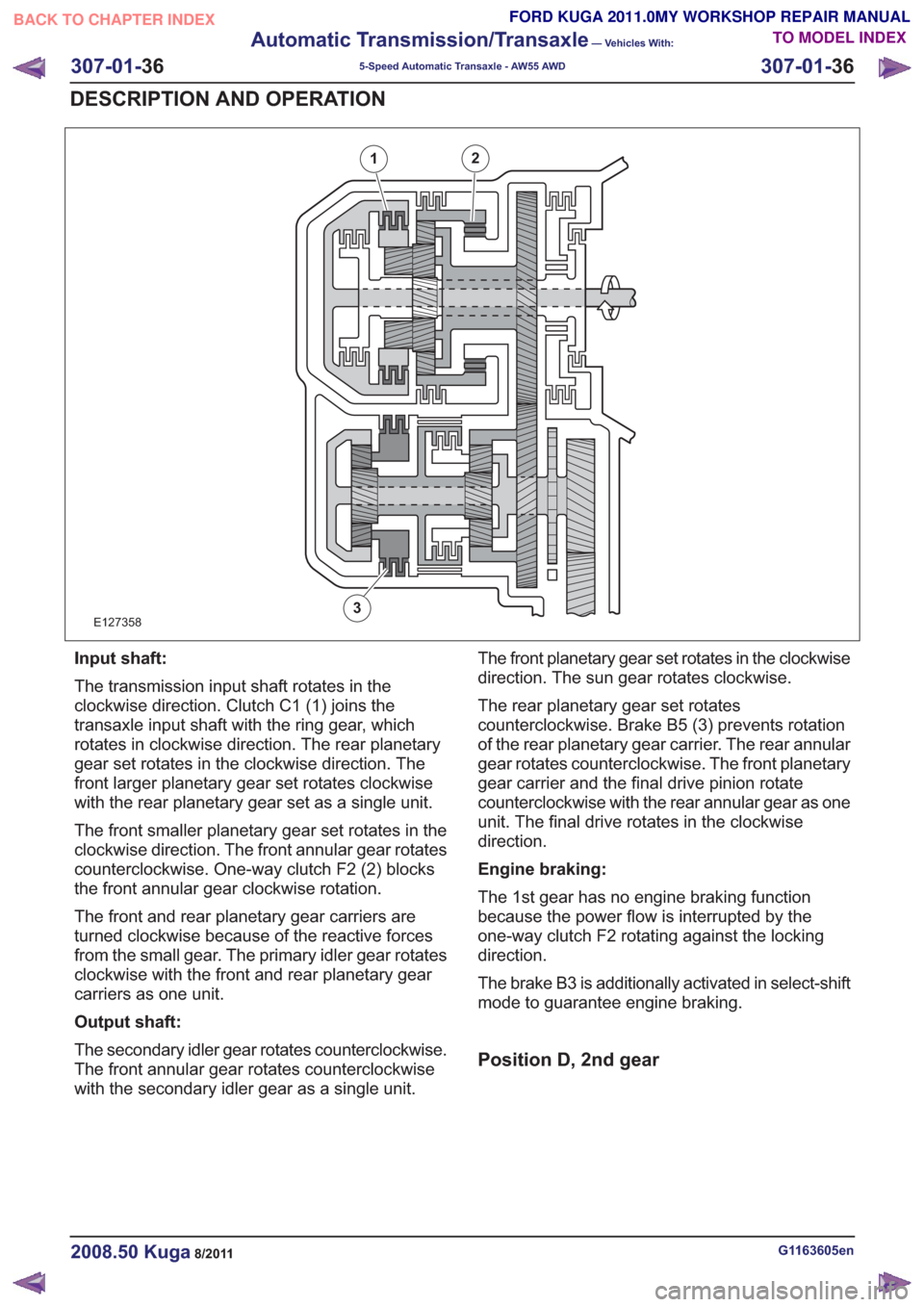
E127358
21
3
Input shaft:
The transmission input shaft rotates in the
clockwise direction. Clutch C1 (1) joins the
transaxle input shaft with the ring gear, which
rotates in clockwise direction. The rear planetary
gear set rotates in the clockwise direction. The
front larger planetary gear set rotates clockwise
with the rear planetary gear set as a single unit.
The front smaller planetary gear set rotates in the
clockwise direction. The front annular gear rotates
counterclockwise. One-way clutch F2 (2) blocks
the front annular gear clockwise rotation.
The front and rear planetary gear carriers are
turned clockwise because of the reactive forces
from the small gear. The primary idler gear rotates
clockwise with the front and rear planetary gear
carriers as one unit.
Output shaft:
The secondary idler gear rotates counterclockwise.
The front annular gear rotates counterclockwise
with the secondary idler gear as a single unit.The front planetary gear set rotates in the clockwise
direction. The sun gear rotates clockwise.
The rear planetary gear set rotates
counterclockwise. Brake B5 (3) prevents rotation
of the rear planetary gear carrier. The rear annular
gear rotates counterclockwise. The front planetary
gear carrier and the final drive pinion rotate
counterclockwise with the rear annular gear as one
unit. The final drive rotates in the clockwise
direction.
Engine braking:
The 1st gear has no engine braking function
because the power flow is interrupted by the
one-way clutch F2 rotating against the locking
direction.
The brake B3 is additionally activated in select-shift
mode to guarantee engine braking.
Position D, 2nd gear
G1163605en2008.50 Kuga8/2011
307-01-
36
Automatic Transmission/Transaxle
— Vehicles With:
5-Speed Automatic Transaxle - AW55 AWD
307-01- 36
DESCRIPTION AND OPERATION
TO MODEL INDEX
BACK TO CHAPTER INDEX
FORD KUGA 2011.0MY WORKSHOP REPAIR MANUAL
Page 1859 of 2057
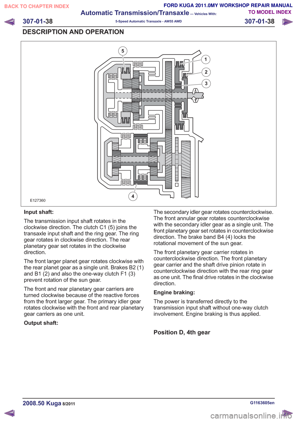
E127360
1
2
3
4
5
Input shaft:
The transmission input shaft rotates in the
clockwise direction. The clutch C1 (5) joins the
transaxle input shaft and the ring gear. The ring
gear rotates in clockwise direction. The rear
planetary gear set rotates in the clockwise
direction.
The front larger planet gear rotates clockwise with
the rear planet gear as a single unit. Brakes B2 (1)
and B1 (2) and also the one-way clutch F1 (3)
prevent rotation of the sun gear.
The front and rear planetary gear carriers are
turned clockwise because of the reactive forces
from the front larger gear. The primary idler gear
rotates clockwise with the front and rear planetary
gear carriers as one unit.
Output shaft:The secondary idler gear rotates counterclockwise.
The front annular gear rotates counterclockwise
with the secondary idler gear as a single unit. The
front planetary gear set rotates in counterclockwise
direction. The brake band B4 (4) locks the
rotational movement of the sun gear.
The front planetary gear carrier rotates in
counterclockwise direction. The front planetary
gear carrier and the shaft drive pinion rotate in
counterclockwise direction with the rear ring gear
as one unit. The final drive rotates in the clockwise
direction.
Engine braking:
The power is transferred directly to the
transmission input shaft without one-way clutch
involvement. Engine braking is thus applied.
Position D, 4th gear
G1163605en2008.50 Kuga8/2011
307-01-
38
Automatic Transmission/Transaxle
— Vehicles With:
5-Speed Automatic Transaxle - AW55 AWD
307-01- 38
DESCRIPTION AND OPERATION
TO MODEL INDEX
BACK TO CHAPTER INDEX
FORD KUGA 2011.0MY WORKSHOP REPAIR MANUAL
Page 1861 of 2057
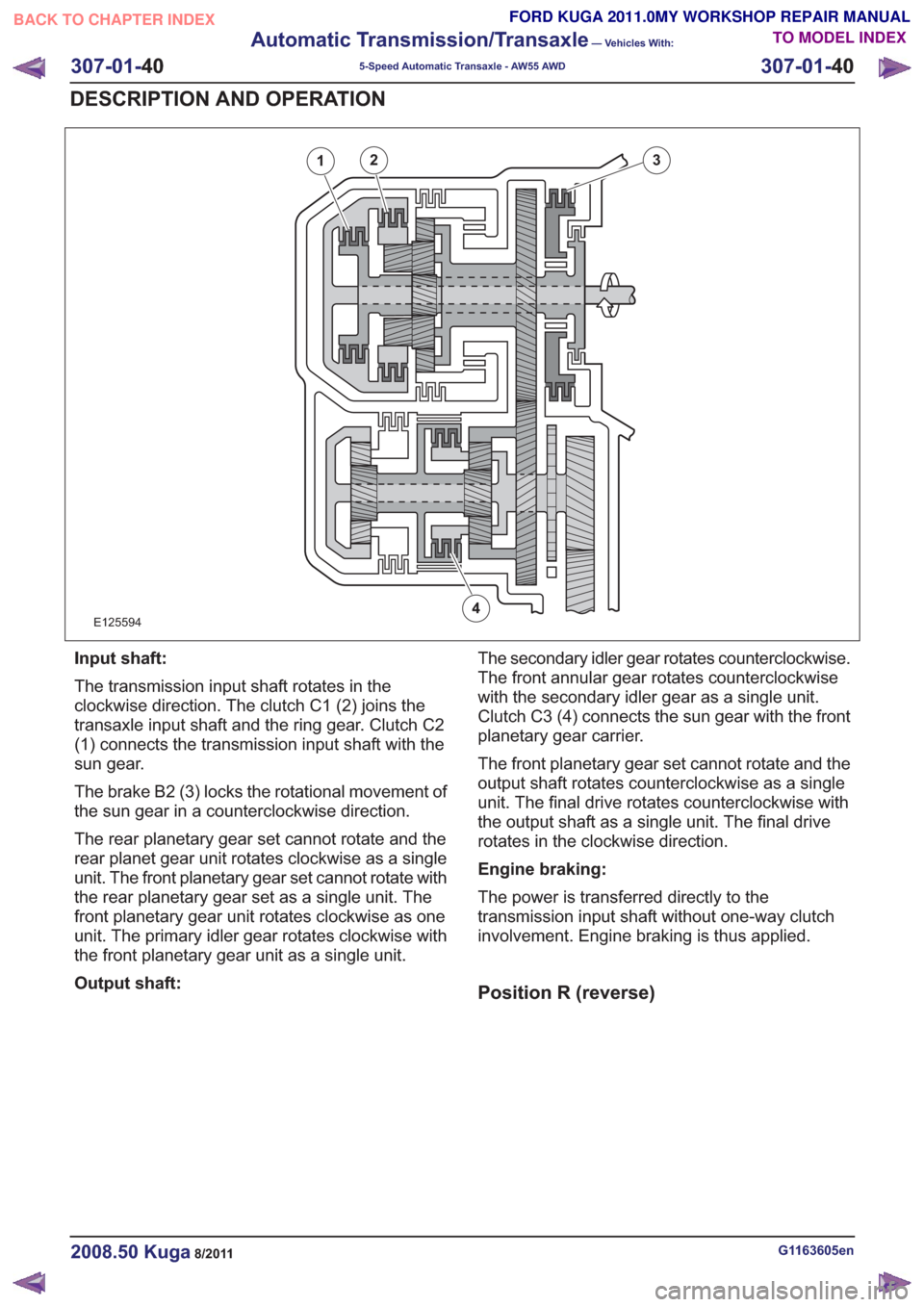
E125594
12
4
3
Input shaft:
The transmission input shaft rotates in the
clockwise direction. The clutch C1 (2) joins the
transaxle input shaft and the ring gear. Clutch C2
(1) connects the transmission input shaft with the
sun gear.
The brake B2 (3) locks the rotational movement of
the sun gear in a counterclockwise direction.
The rear planetary gear set cannot rotate and the
rear planet gear unit rotates clockwise as a single
unit. The front planetary gear set cannot rotate with
the rear planetary gear set as a single unit. The
front planetary gear unit rotates clockwise as one
unit. The primary idler gear rotates clockwise with
the front planetary gear unit as a single unit.
Output shaft:The secondary idler gear rotates counterclockwise.
The front annular gear rotates counterclockwise
with the secondary idler gear as a single unit.
Clutch C3 (4) connects the sun gear with the front
planetary gear carrier.
The front planetary gear set cannot rotate and the
output shaft rotates counterclockwise as a single
unit. The final drive rotates counterclockwise with
the output shaft as a single unit. The final drive
rotates in the clockwise direction.
Engine braking:
The power is transferred directly to the
transmission input shaft without one-way clutch
involvement. Engine braking is thus applied.
Position R (reverse)
G1163605en2008.50 Kuga8/2011
307-01-
40
Automatic Transmission/Transaxle
— Vehicles With:
5-Speed Automatic Transaxle - AW55 AWD
307-01- 40
DESCRIPTION AND OPERATION
TO MODEL INDEX
BACK TO CHAPTER INDEX
FORD KUGA 2011.0MY WORKSHOP REPAIR MANUAL
Page 1862 of 2057
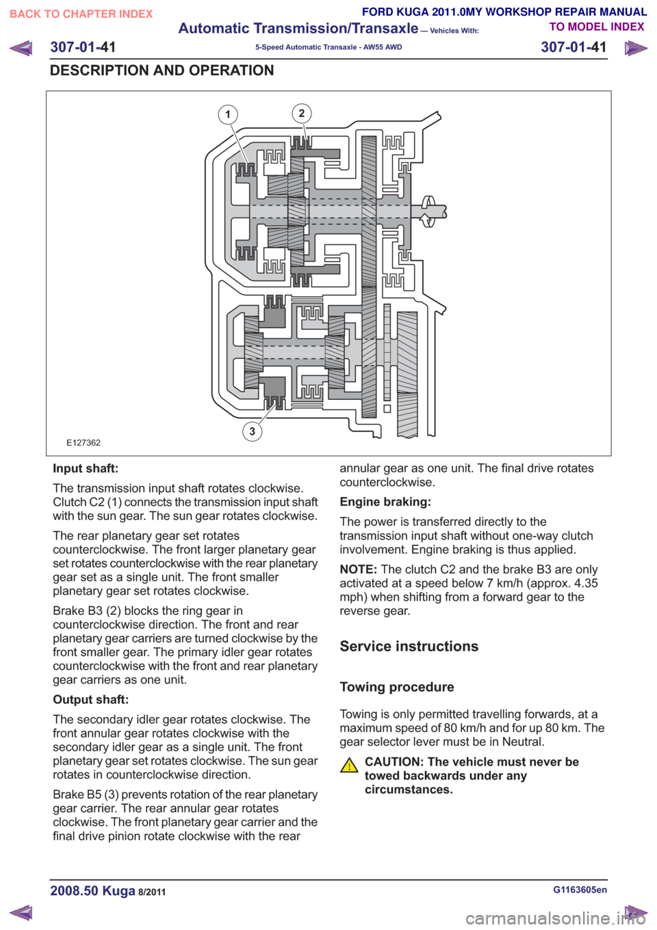
E127362
12
3
Input shaft:
The transmission input shaft rotates clockwise.
Clutch C2 (1) connects the transmission input shaft
with the sun gear. The sun gear rotates clockwise.
The rear planetary gear set rotates
counterclockwise. The front larger planetary gear
set rotates counterclockwise with the rear planetary
gear set as a single unit. The front smaller
planetary gear set rotates clockwise.
Brake B3 (2) blocks the ring gear in
counterclockwise direction. The front and rear
planetary gear carriers are turned clockwise by the
front smaller gear. The primary idler gear rotates
counterclockwise with the front and rear planetary
gear carriers as one unit.
Output shaft:
The secondary idler gear rotates clockwise. The
front annular gear rotates clockwise with the
secondary idler gear as a single unit. The front
planetary gear set rotates clockwise. The sun gear
rotates in counterclockwise direction.
Brake B5 (3) prevents rotation of the rear planetary
gear carrier. The rear annular gear rotates
clockwise. The front planetary gear carrier and the
final drive pinion rotate clockwise with the rearannular gear as one unit. The final drive rotates
counterclockwise.
Engine braking:
The power is transferred directly to the
transmission input shaft without one-way clutch
involvement. Engine braking is thus applied.
NOTE:
The clutch C2 and the brake B3 are only
activated at a speed below 7 km/h (approx. 4.35
mph) when shifting from a forward gear to the
reverse gear.
Service instructions
Towing procedure
Towing is only permitted travelling forwards, at a
maximum speed of 80 km/h and for up 80 km. The
gear selector lever must be in Neutral.
CAUTION: The vehicle must never be
towed backwards under any
circumstances.
G1163605en2008.50 Kuga8/2011
307-01- 41
Automatic Transmission/Transaxle
— Vehicles With:
5-Speed Automatic Transaxle - AW55 AWD
307-01- 41
DESCRIPTION AND OPERATION
TO MODEL INDEX
BACK TO CHAPTER INDEX
FORD KUGA 2011.0MY WORKSHOP REPAIR MANUAL
Page 2010 of 2057
Speed Control
Inspection and Verification
1. Verify the customer concern by operating thesystem.
2. Visually inspect for obvious signs of mechanical or electrical damage.
Visual Inspection Chart
Electrical
Mechanical
– Fuse(s)
– Connections
– Wiring harness
– Clockspring
– Loose or corrodedelectrical
connector(s)
– Speed control switch
– Brake pedal position (BPP) deactivation
switch
– Clutch pedal posi- tion (CPP) deactiva-
tion Switch
– Powertrain control module (PCM)
– Central junction box (CJB)
– Brake pedal
– Clutch pedal
3. NOTE: Not all passenger junction box (PJB) variants support the speed control system.
NOTE: If the PJB is configured for speed control
disable, speed control operation is not transmitted,
no Diagnostic Trouble Codes (DTCs) are
generated.
If an obvious cause for an observed or reported
concern is found, correct the cause (if possible)
before proceeding to the next step.
4. If the cause is not visually evident, verify the symptom and refer to the diagnostic tab within
the Ford approved diagnostic tool.
G1054908en2008.50 Kuga8/2011
310-03- 7
Speed Control
310-03- 7
DIAGNOSIS AND TESTING
TO MODEL INDEX
BACK TO CHAPTER INDEX
FORD KUGA 2011.0MY WORKSHOP REPAIR MANUAL