network FORD KUGA 2011 1.G Owner's Manual
[x] Cancel search | Manufacturer: FORD, Model Year: 2011, Model line: KUGA, Model: FORD KUGA 2011 1.GPages: 2057
Page 1782 of 2057
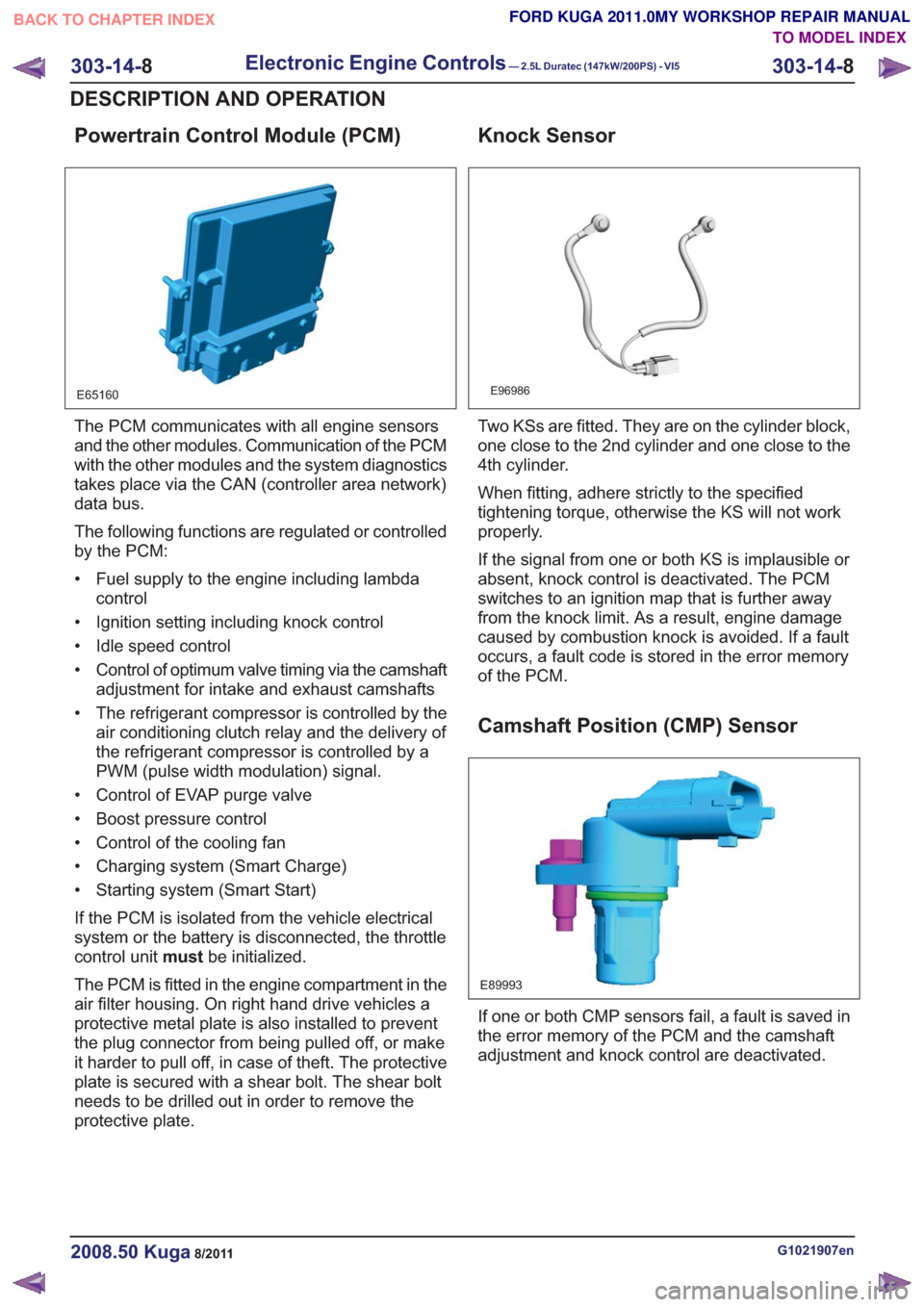
Powertrain Control Module (PCM)
E65160
The PCM communicates with all engine sensors
and the other modules. Communication of the PCM
with the other modules and the system diagnostics
takes place via the CAN (controller area network)
data bus.
The following functions are regulated or controlled
by the PCM:
• Fuel supply to the engine including lambdacontrol
• Ignition setting including knock control
• Idle speed control
• Control of optimum valve timing via the camshaft adjustment for intake and exhaust camshafts
• The refrigerant compressor is controlled by the air conditioning clutch relay and the delivery of
the refrigerant compressor is controlled by a
PWM (pulse width modulation) signal.
• Control of EVAP purge valve
• Boost pressure control
• Control of the cooling fan
• Charging system (Smart Charge)
• Starting system (Smart Start)
If the PCM is isolated from the vehicle electrical
system or the battery is disconnected, the throttle
control unit mustbe initialized.
The PCM is fitted in the engine compartment in the
air filter housing. On right hand drive vehicles a
protective metal plate is also installed to prevent
the plug connector from being pulled off, or make
it harder to pull off, in case of theft. The protective
plate is secured with a shear bolt. The shear bolt
needs to be drilled out in order to remove the
protective plate.
Knock Sensor
E96986
Two KSs are fitted. They are on the cylinder block,
one close to the 2nd cylinder and one close to the
4th cylinder.
When fitting, adhere strictly to the specified
tightening torque, otherwise the KS will not work
properly.
If the signal from one or both KS is implausible or
absent, knock control is deactivated. The PCM
switches to an ignition map that is further away
from the knock limit. As a result, engine damage
caused by combustion knock is avoided. If a fault
occurs, a fault code is stored in the error memory
of the PCM.
Camshaft Position (CMP) Sensor
E89993
If one or both CMP sensors fail, a fault is saved in
the error memory of the PCM and the camshaft
adjustment and knock control are deactivated.
G1021907en2008.50 Kuga8/2011
303-14- 8
Electronic Engine Controls— 2.5L Duratec (147kW/200PS) - VI5303-14-
8
DESCRIPTION AND OPERATION
TO MODEL INDEX
BACK TO CHAPTER INDEX
FORD KUGA 2011.0MY WORKSHOP REPAIR MANUAL
Page 1790 of 2057
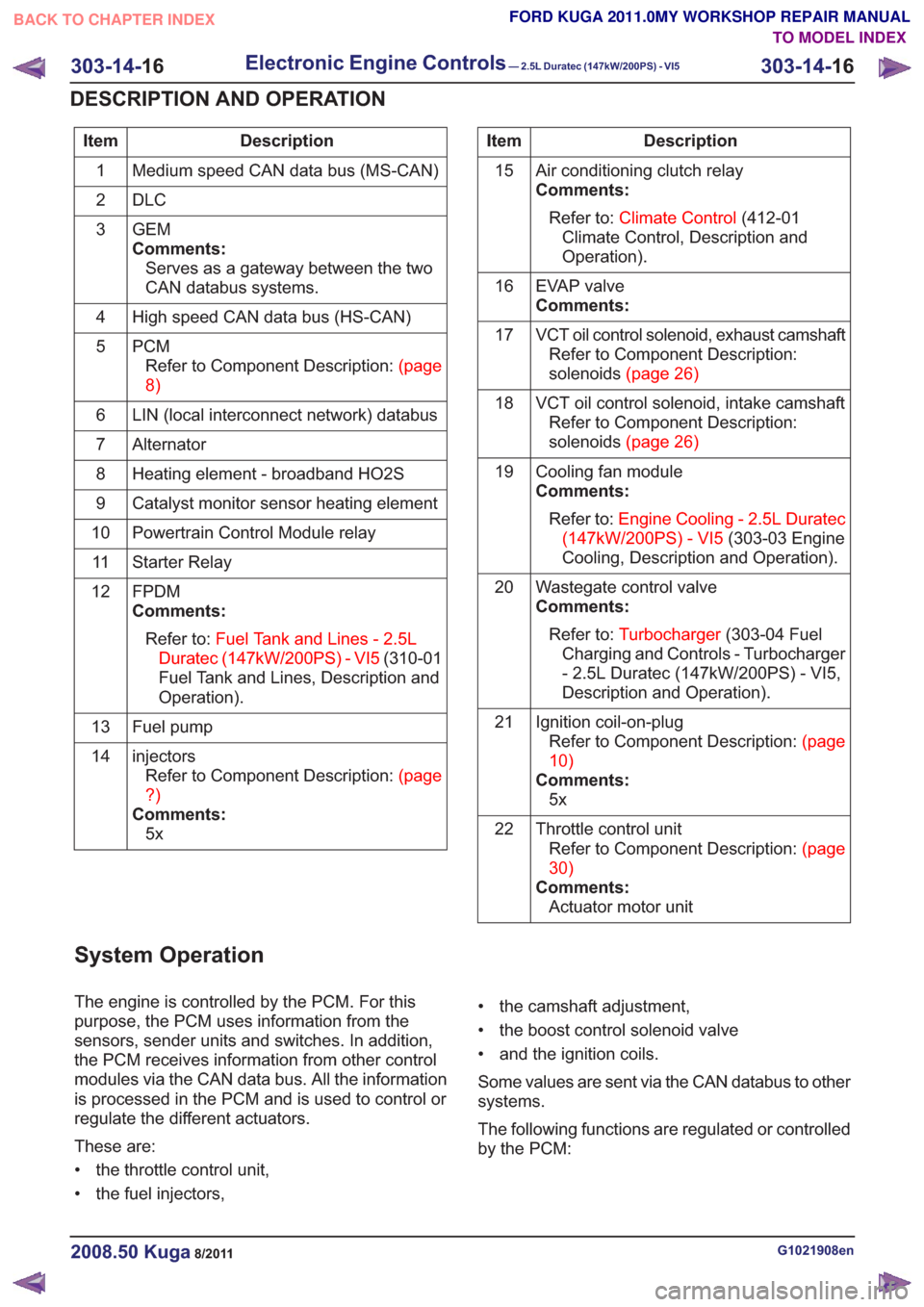
Description
Item
Medium speed CAN data bus (MS-CAN)
1
DLC
2
GEM
Comments:Serves as a gateway between the two
CAN databus systems.
3
High speed CAN data bus (HS-CAN)
4
PCMRefertoComponentDescription:(page
8)
5
LIN (local interconnect network) databus
6
Alternator
7
Heating element - broadband HO2S
8
Catalyst monitor sensor heating element
9
Powertrain Control Module relay
10
Starter Relay
11
FPDM
Comments:Refer to: Fuel Tank and Lines - 2.5L
Duratec (147kW/200PS) - VI5 (310-01
Fuel Tank and Lines, Description and
Operation).
12
Fuel pump
13
injectorsRefertoComponentDescription:(page
?)
Comments: 5x
14Description
Item
Air conditioning clutch relay
Comments:Refer to: Climate Control (412-01
Climate Control, Description and
Operation).
15
EVAP valve
Comments:
16
VCT oil control solenoid, exhaust camshaftRefer to Component Description:
solenoids(page26)
17
VCT oil control solenoid, intake camshaftRefer to Component Description:
solenoids(page26)
18
Cooling fan module
Comments:Refer to: Engine Cooling - 2.5L Duratec
(147kW/200PS) - VI5 (303-03 Engine
Cooling, Description and Operation).
19
Wastegate control valve
Comments:Refer to: Turbocharger (303-04 Fuel
Charging and Controls - Turbocharger
- 2.5L Duratec (147kW/200PS) - VI5,
Description and Operation).
20
Ignition coil-on-plugRefertoComponentDescription:(page
10)
Comments: 5x
21
Throttle control unitRefertoComponentDescription:(page
30)
Comments: Actuator motor unit
22
System Operation
The engine is controlled by the PCM. For this
purpose, the PCM uses information from the
sensors, sender units and switches. In addition,
the PCM receives information from other control
modules via the CAN data bus. All the information
is processed in the PCM and is used to control or
regulate the different actuators.
These are:
• the throttle control unit,
• the fuel injectors, • the camshaft adjustment,
• the boost control solenoid valve
• and the ignition coils.
Some values are sent via the CAN databus to other
systems.
The following functions are regulated or controlled
by the PCM:
G1021908en2008.50 Kuga8/2011
303-14-
16
Electronic Engine Controls— 2.5L Duratec (147kW/200PS) - VI5303-14-
16
DESCRIPTION AND OPERATION
TO MODEL INDEX
BACK TO CHAPTER INDEX
FORD KUGA 2011.0MY WORKSHOP REPAIR MANUAL
Page 1844 of 2057
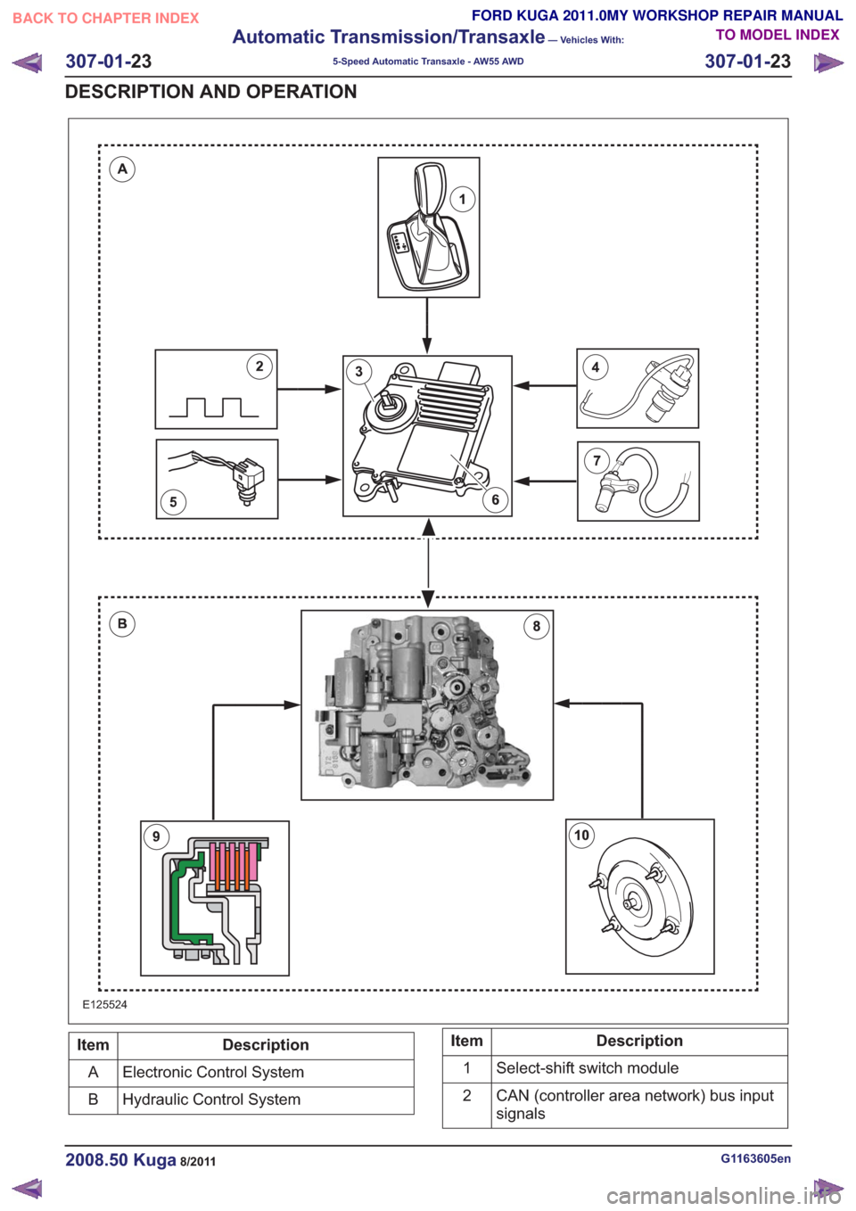
E125524
Description
Item
Electronic Control System
A
Hydraulic Control System
BDescription
Item
Select-shift switch module
1
CAN (controller area network) bus input
signals
2
G1163605en2008.50 Kuga8/2011
307-01-
23
Automatic Transmission/Transaxle
— Vehicles With:
5-Speed Automatic Transaxle - AW55 AWD
307-01- 23
DESCRIPTION AND OPERATION
TO MODEL INDEX
BACK TO CHAPTER INDEX
FORD KUGA 2011.0MY WORKSHOP REPAIR MANUAL
Page 1848 of 2057
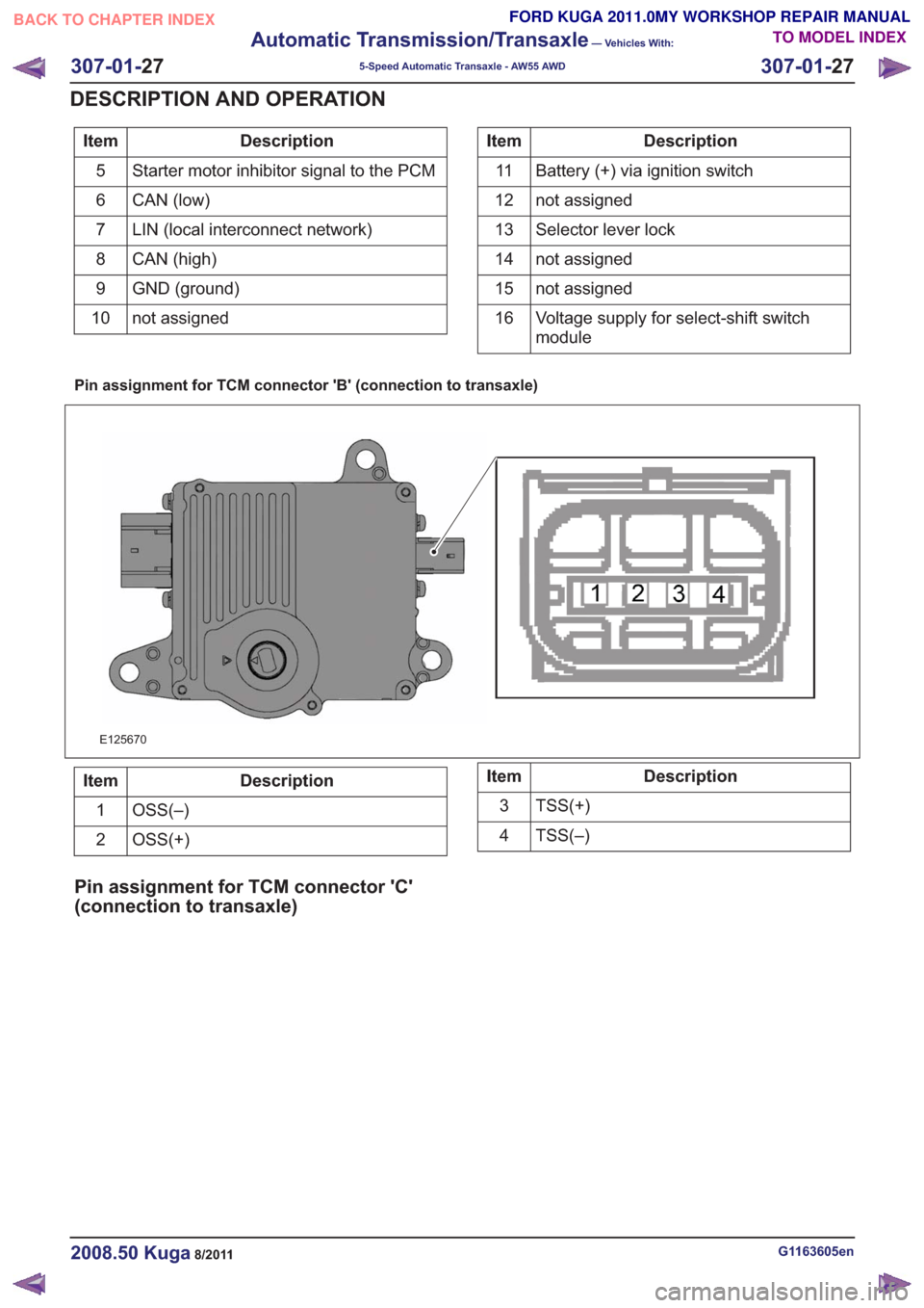
Description
Item
Starter motor inhibitor signal to the PCM
5
CAN (low)
6
LIN (local interconnect network)
7
CAN (high)
8
GND (ground)
9
not assigned
10Description
Item
Battery (+) via ignition switch
11
not assigned
12
Selector lever lock
13
not assigned
14
not assigned
15
Voltage supply for select-shift switch
module
16
Pin assignment for TCM connector 'B' (connection to transaxle)
E125670
Description
Item
OSS(–)
1
OSS(+)
2Description
Item
TSS(+)
3
TSS(–)
4
Pin assignment for TCM connector 'C'
(connection to transaxle)
G1163605en2008.50 Kuga8/2011
307-01- 27
Automatic Transmission/Transaxle
— Vehicles With:
5-Speed Automatic Transaxle - AW55 AWD
307-01- 27
DESCRIPTION AND OPERATION
TO MODEL INDEX
BACK TO CHAPTER INDEX
FORD KUGA 2011.0MY WORKSHOP REPAIR MANUAL
Page 2007 of 2057
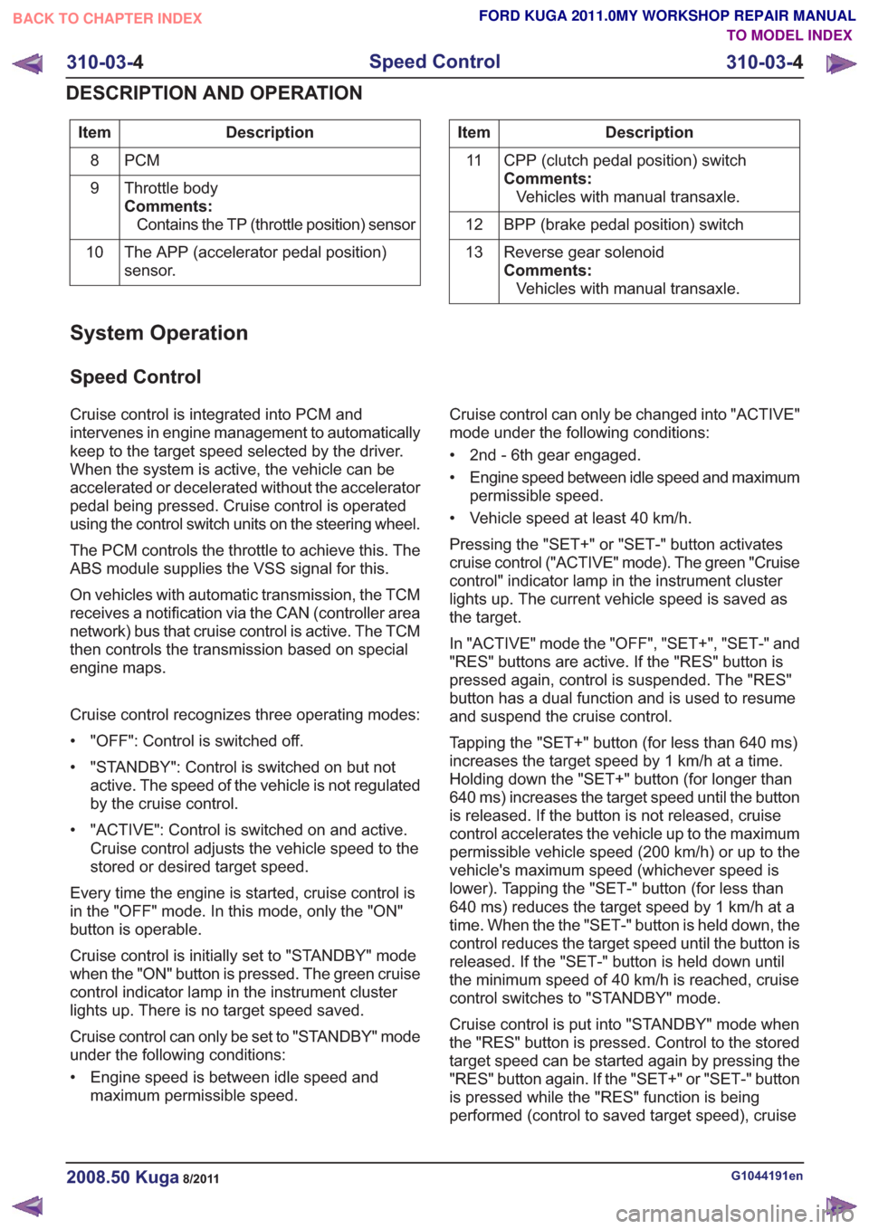
Description
Item
PCM
8
Throttle body
Comments:Contains the TP (throttle position) sensor
9
The APP (accelerator pedal position)
sensor.
10Description
Item
CPP (clutch pedal position) switch
Comments:Vehicles with manual transaxle.
11
BPP (brake pedal position) switch
12
Reverse gear solenoid
Comments:Vehicles with manual transaxle.
13
System Operation
Speed Control
Cruise control is integrated into PCM and
intervenes in engine management to automatically
keep to the target speed selected by the driver.
When the system is active, the vehicle can be
accelerated or decelerated without the accelerator
pedal being pressed. Cruise control is operated
using the control switch units on the steering wheel.
The PCM controls the throttle to achieve this. The
ABS module supplies the VSS signal for this.
On vehicles with automatic transmission, the TCM
receives a notification via the CAN (controller area
network) bus that cruise control is active. The TCM
then controls the transmission based on special
engine maps.
Cruise control recognizes three operating modes:
• "OFF": Control is switched off.
• "STANDBY": Control is switched on but not
active. The speed of the vehicle is not regulated
by the cruise control.
• "ACTIVE": Control is switched on and active. Cruise control adjusts the vehicle speed to the
stored or desired target speed.
Every time the engine is started, cruise control is
in the "OFF" mode. In this mode, only the "ON"
button is operable.
Cruise control is initially set to "STANDBY" mode
when the "ON" button is pressed. The green cruise
control indicator lamp in the instrument cluster
lights up. There is no target speed saved.
Cruise control can only be set to "STANDBY" mode
under the following conditions:
• Engine speed is between idle speed and maximum permissible speed. Cruise control can only be changed into "ACTIVE"
mode under the following conditions:
• 2nd - 6th gear engaged.
• Engine speed between idle speed and maximum
permissible speed.
• Vehicle speed at least 40 km/h.
Pressing the "SET+" or "SET-" button activates
cruise control ("ACTIVE" mode). The green "Cruise
control" indicator lamp in the instrument cluster
lights up. The current vehicle speed is saved as
the target.
In "ACTIVE" mode the "OFF", "SET+", "SET-" and
"RES" buttons are active. If the "RES" button is
pressed again, control is suspended. The "RES"
button has a dual function and is used to resume
and suspend the cruise control.
Tapping the "SET+" button (for less than 640 ms)
increases the target speed by 1 km/h at a time.
Holding down the "SET+" button (for longer than
640 ms) increases the target speed until the button
is released. If the button is not released, cruise
control accelerates the vehicle up to the maximum
permissible vehicle speed (200 km/h) or up to the
vehicle's maximum speed (whichever speed is
lower). Tapping the "SET-" button (for less than
640 ms) reduces the target speed by 1 km/h at a
time. When the the "SET-" button is held down, the
control reduces the target speed until the button is
released. If the "SET-" button is held down until
the minimum speed of 40 km/h is reached, cruise
control switches to "STANDBY" mode.
Cruise control is put into "STANDBY" mode when
the "RES" button is pressed. Control to the stored
target speed can be started again by pressing the
"RES" button again. If the "SET+" or "SET-" button
is pressed while the "RES" function is being
performed (control to saved target speed), cruise
G1044191en2008.50 Kuga8/2011
310-03- 4
Speed Control
310-03- 4
DESCRIPTION AND OPERATION
TO MODEL INDEX
BACK TO CHAPTER INDEX
FORD KUGA 2011.0MY WORKSHOP REPAIR MANUAL