fuel cap FORD KUGA 2011 1.G Workshop Manual
[x] Cancel search | Manufacturer: FORD, Model Year: 2011, Model line: KUGA, Model: FORD KUGA 2011 1.GPages: 2057
Page 165 of 2057
System Operation
Electric Booster Heater
In diesel vehicles which give off little residual heat,
a booster heater is used to heat the passenger
compartment rapidly in the case of low ambient
temperatures.
If the interior temperature has been set to HI, or if
the heater controls have been switched to the
highest setting, the two-zone air conditioning
system sends an "electric booster heater ON"
request signal to the CAN (controller area network)
via the medium speed GEM bus. If a manual air
conditioning system is installed, the signal is
transmitted via a conventional cable connection.
The GEM switches on the electric booster heater
depending on the following parameters:
• Engine coolant temperature is below 60 °C.
• Ambient air temperature is below 10 °C.
• Sufficient generator capacity is available.
The electric booster heater electronics activate
three output stages as a function of a pulse width
modulated signal PWM (pulse width modulation)
generated by the GEM. The output stages switch
the three heating elements of the electric booster
heater ON or OFF individually, whereby the heating
periods of the individual elements can overlap. Due
to the variable switch-on duration, continuously
variable temperature control is possible. The overall
heating power of the three heating elements is
linearly proportional to the PWM signal. If the PWM
signal is below 10% or above 95%, the electric
booster heater is not activated.
The electric booster heater is switched off when
an engine coolant temperature of 70°C or an
ambient air temperature of 20°C is exceeded.
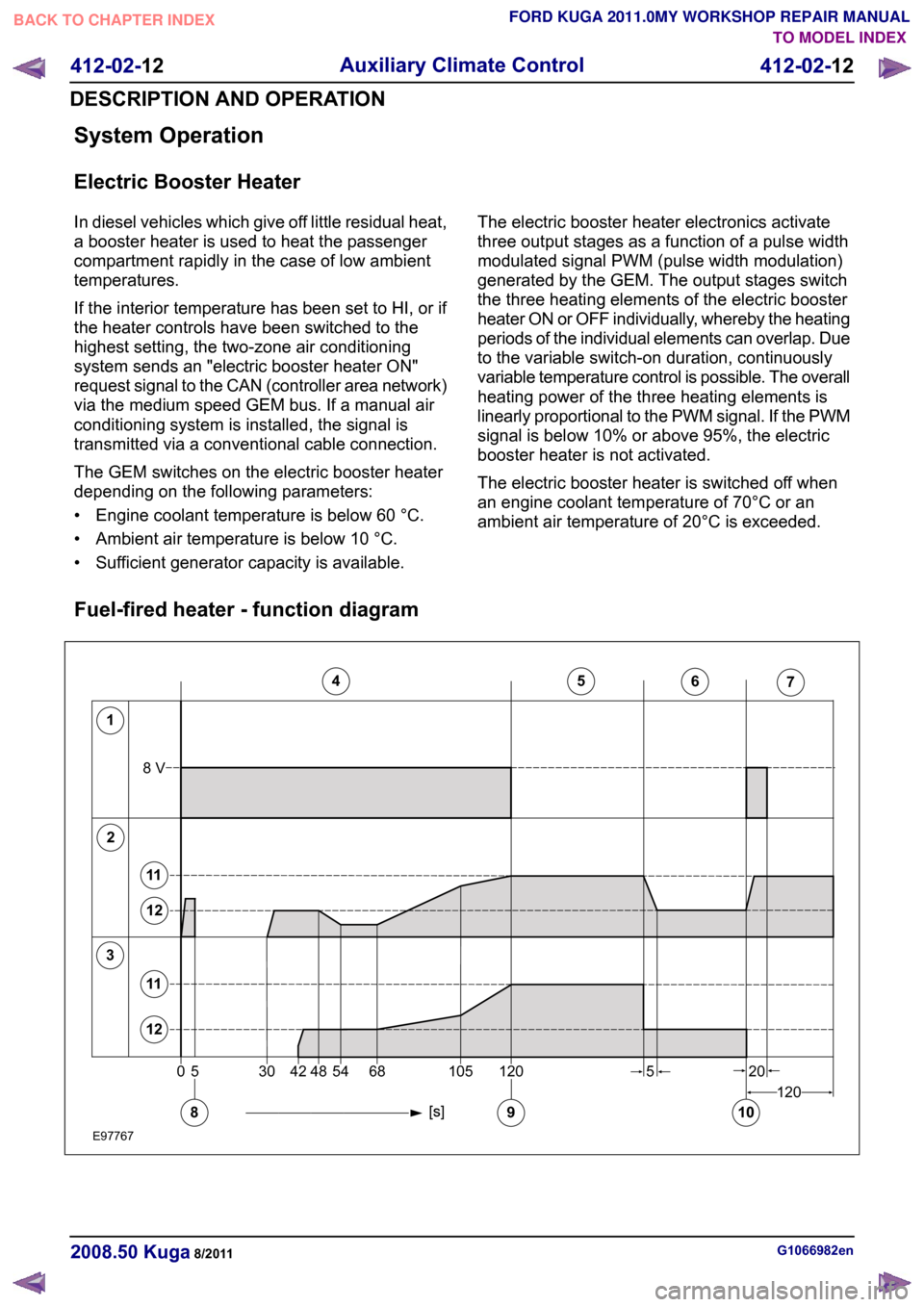
Fuel-fired heater - function diagram G1066982en
2008.50 Kuga 8/2011 412-02-12
Auxiliary Climate Control
412-02-12
DESCRIPTION AND OPERATIONTO MODEL INDEX
BACK TO CHAPTER INDEX
FORD KUGA 2011.0MY WORKSHOP REPAIR MANUAL12345671205304254481201056820108V58911121112E977670
Page 166 of 2057

Description
Item
Glow plug
1
Combustion Air Blower
2
Fuel pump
3
Fuel-fired heater on
4
Fuel-fired heater - large regulating step
5
Fuel-fired heater - small regulating step
6 Description
Item
Fuel-fired heater off
7
Blower motor on
8
Flame detection
9
Blower motor off
10
Large regulating step
11
Small regulating step
12
Boost heat mode
When the engine is running, the booster heater
helps the engine to heat the passenger
compartment at low ambient temperatures.
When the coolant temperature reaches 30 °C, the
control unit transmits a switch-on signal for the
passenger compartment blower via the CAN bus.
When the coolant temperature drops, the blower
remains on until the temperature reaches 20 °C
whereupon it is deactivated.
The fuel tank must be filled to at least 14% for the
system to be switched on. If the fuel level drops
below 8% then the system is switched off.
In boost mode, the fuel fired booster heater is only
switched on if all of the following criteria are met:
• Engine speed above 500 rpm. The fuel fired booster heater is not allowed to start up while
the engine is being cranked; this prevents a
shut-down due to low voltage if the battery
charge is low.
• Ambient temperature below 5 °C.
• Fuel level above 14% of total capacity.
• Function is active on the trip computer menu.
One of the following conditions is sufficient to
switch off the booster heater in boost heat mode:
• Engine speed below 500 rpm.
• Ambient temperature above 11 °C.
• Function is active on the trip computer menu.
• Fuel level below 8% of total capacity.
Programmable fuel fired booster heater
The programmable fuel fired booster heater has
two operating modes:
• Instant start
• Programmed start
The heater status is displayed on the instrument
cluster display. The parking heater mode is controlled via a menu in the message centre. The
fuel fired booster heater can be activated and
deactivated via the message centre. (If set to 'Auto'
the system is activated, if set to 'Off' the system is
completely deactivated)
Immediate start-up of the booster
heater
This function enables the fuel-fired booster heater
to be switched on manually when the engine is not
running. This function is activated via the menu on
the driver information system.
The ignition key must be in the II" position before
this menu can be accessed. The timer function of
the booster heater remains active when the ignition
key is in position "0".
After an immediate start-up of the booster heater
it is switched off again after 30 minutes (or if the
fuel level in the fuel tank drops below 8%). The
booster heater stops within 2 minutes of the engine
starting. This leaves enough time to check whether
the switch-on conditions for boost heat mode have
been met, thus preventing the booster heater from
having to switch off and switch back on again. The
heater can be switched off manually at any time
from the menu.
Programmed start-up of the booster
heater
The driver can use a menu to adjust the time at
which the vehicle is to be pre-heated. The following
options are available:
• Time setting. One or two times can be
programmed for each day of the week. It is
possible to program days either individually or
together in groups (Mon-Sun/Mon-Sat/Mon-Fri).
• Time and data setting
With the first option, the fuel-fired booster heater
will start repeatedly without needing to be G1066982en
2008.50 Kuga 8/2011 412-02-13
Auxiliary Climate Control
412-02-13
DESCRIPTION AND OPERATIONTO MODEL INDEX
BACK TO CHAPTER INDEX
FORD KUGA 2011.0MY WORKSHOP REPAIR MANUAL
Page 190 of 2057

Instrument Cluster
Refer to
Wiring Diagrams Section 413-01, for
schematic and connector information. General Equipment
The Ford approved diagnostic tool
Inspection and Verification
1. Verify the customer concern.
2. Visually inspect for obvious signs of mechanical
or electrical damage.
Visual Inspection Chart Electrical
Mechanical
– Fuse(s)
– Wiring harness
– Electricalconnector(s)
– Instrument cluster
– Light emitting diode(s) (LED)(s)
– Engine oil filter
– Engine oil level
–
Engine coolant level
– Oil pressure switch
– Engine coolant level
– Coolant thermostat
– Engine coolant temperature (ECT)
sensor
– Fuel gauge
– Collapsed or damaged fuel tank
– Recirculation hose
– Fuel tank filler pipe/hose
– Indicated fuel level
– Fuel lines
– Fuel tank filler cap
– Fuel filter (external to the fuel tank)
– Fuel tank
– Door adjustment
3. If an obvious cause for an observed or reported concern is found, correct the cause (if possible)
before proceeding to the next step.
4. NOTE: If none of the following warning indicators are operating correctly this may
indicate a concern with the central junction
box (CJB). If only one or two of the following
warning indicators are not operating
correctly this may indicate an instrument
cluster concern. Verify the following warning indicators are
working correctly:
• Charging.
• Turn signals.
• Headlamps.
5. If the cause is not visually evident, verify the symptom and refer to the diagnostic tab within
the Ford approved diagnostic tool.
Configuration of the Instrument Cluster
The instrument cluster is a programmable module,
which must be configured by selecting the
Programmable Module Installation Routine on the
Ford approved diagnostic tool.
NOTE: When the new instrument cluster has been
configured with the odometer value, its
configuration cannot be decreased or matched. A
new configuration will result in an increase in the
displayed odometer value by a minimum of two
units.
NOTE: The odometer value must be recorded from
the original instrument cluster before removal.
If the odometer value cannot be obtained from
the original instrument cluster (display failure)
the customer should supply the approximate
value.
The following features will need to be configured
when a new instrument cluster is installed:
• Anti-lock Brake System (ABS)
• All wheel drive
• Keyless vehicle entry
• Electronic power assisted steering
• Trip computer
• Voice control
• Parking aid
• Belt minder
• Safety belt not fastened
• Right hand drive
• Overspeed warning
• Reverse warning
• Turbocharger boost pressure
• Speed control
• Auxiliary heater
• Suspension control
• Washer fluid sensor G1054964en
2008.50 Kuga 8/2011 413-01-7
Instrument Cluster
413-01-7
DIAGNOSIS AND TESTINGTO MODEL INDEX
BACK TO CHAPTER INDEX
FORD KUGA 2011.0MY WORKSHOP REPAIR MANUAL
Page 191 of 2057

• Navigation
• Fuel cap release
• Engine type
• Display language
In addition the new instrument cluster will require
the original odometer value to be entered.
After the installation and configuration of a new
instrument cluster. The passive anti-theft system
(PATS) will require programming by selecting the
Security Access routine on the Ford approved
diagnostic tool.
G1054964en
2008.50 Kuga 8/2011 413-01-8
Instrument Cluster
413-01-8
DIAGNOSIS AND TESTINGTO MODEL INDEX
BACK TO CHAPTER INDEX
FORD KUGA 2011.0MY WORKSHOP REPAIR MANUAL
Page 1525 of 2057
Action
Possible Sources
Symptom
• CHECK the engine compon-ents for wear or damage. Make
sure that all components are
within specification. INSTALL
new components as necessary.
Engine - 2.5L Duratec-ST (VI5)
-
REFER to: Specifications (303-
01 Engine - 2.5L Duratec
(147kW/200PS) - VI5,
Specifications).
Engine - 2.0L Duratorq-TDCi
(DW) Diesel -
• Engine components
- Pistons.
- Piston rings.
- Connecting rod big end,main bearing or thrust
bearing journals.
- Connecting rods bent or damaged.
• Noisy running or engine noise
Engine - Oil Leaks
NOTE:
Before installing new gaskets or oil seals,
make sure that the fault is clearly established.
If the oil leak cannot be identified clearly by a visual
inspection, carry out an ultraviolet (UV) test:
Ultraviolet (UV) Testing
1. Clean the engine and transmission with a suitable cleaning fluid.
2. Pour the UV-test fluid in accordance with the quantity specified by the manufacturer through
the oil filler neck into the engine and install the
oil filler cap.
WARNING: Vehicles with manual transaxle,
shift the transaxle into Neutral. Failure to
follow this instruction may result in
personal injury.
3. Start the engine and let it run for about five minutes.
4. Switch off the engine.
NOTE: If no leak can be found, road test the
vehicle under various loads and check the engine
for leaks again.
5. Check the engine for oil leaks using a suitable UV lamp.
6. Rectify any leaks found and check the engine for oil leaks.
Measure the compression pressure
NOTE: The powertrain control module (PCM)
receives an error message when the fuel pump
relay is removed or electrical components are disconnected. This error message must be deleted
from the fault memory using the Ford diagnostic
equipment after completing the compression test.
NOTE:
Valve clearance must be set correctly
before performing a compression test. Make sure
the engine is at the normal operating temperature.
NOTE: The varying design of compression
checking devices and fluctuating starter motor
speeds normally only allows for a comparison to
be made of the compression pressures in all
cylinders.
G1055128en2008.50 Kuga8/2011
303-00- 9
Engine System - General Information
303-00- 9
DIAGNOSIS AND TESTING
TO MODEL INDEX
BACK TO CHAPTER INDEX
FORD KUGA 2011.0MY WORKSHOP REPAIR MANUAL
Page 1603 of 2057
38.
E67408
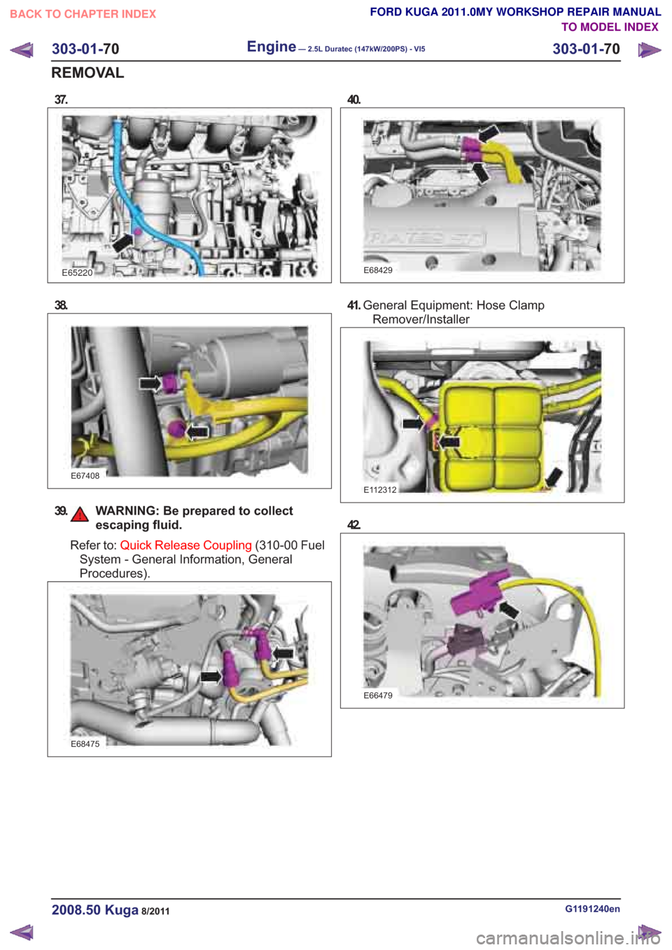
39. WARNING: Be prepared to collectescaping fluid.
Refer to: Quick Release Coupling (310-00 Fuel
System - General Information, General
Procedures).
E68475
41. General Equipment: Hose Clamp
Remover/Installer
E112312
42.
E66479
G1191240en2008.50 Kuga8/2011
303-01- 70
Engine— 2.5L Duratec (147kW/200PS) - VI5303-01-
70
REMOVAL
FORD KUGA 2011.0MY WORKSHOP REPAIR MANUAL
TO MODEL INDEX
BACK TO CHAPTER INDEX
E65220
37.40.
E68429
Page 1716 of 2057
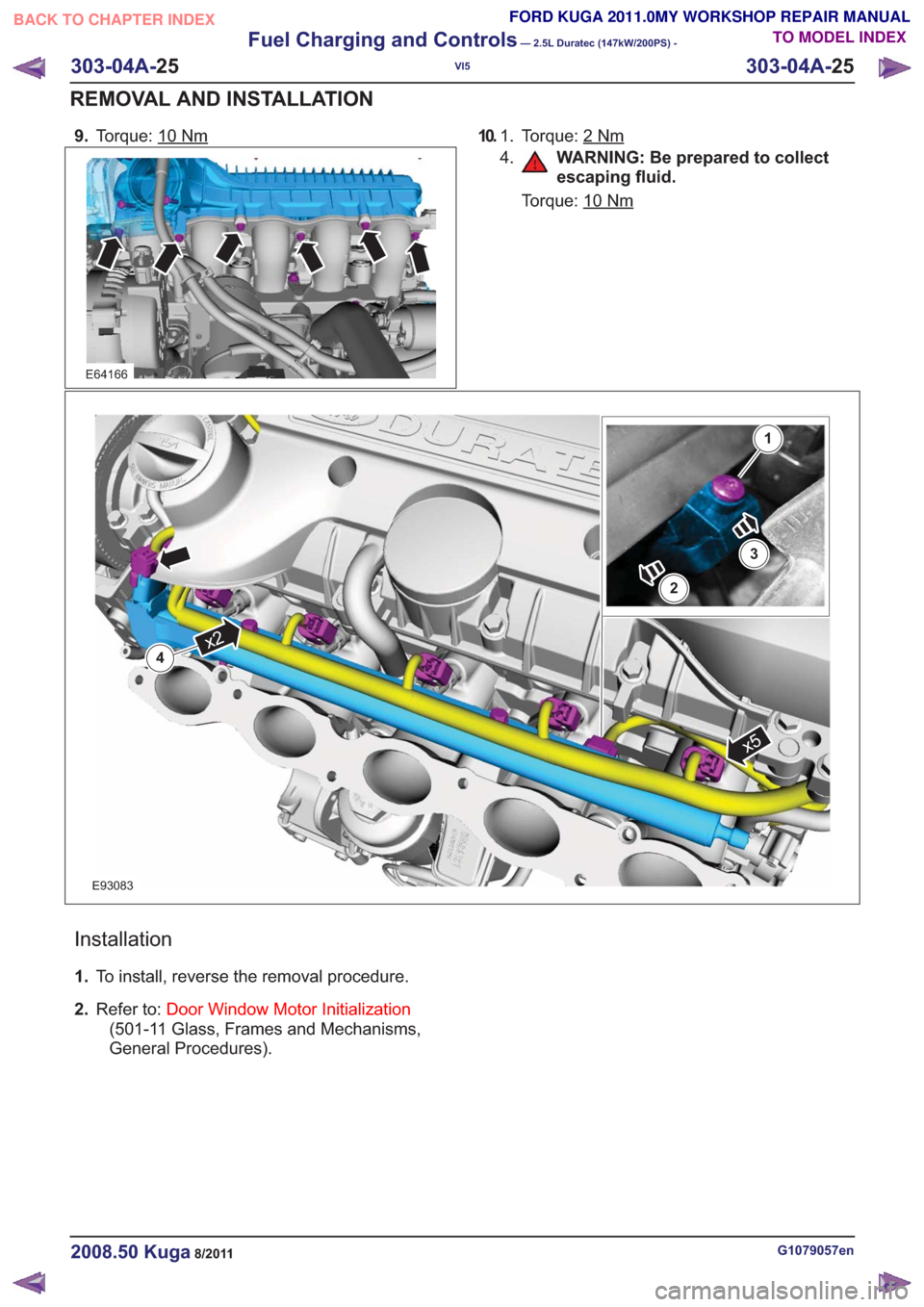
9.Torque: 10Nm
E64166
10. To r q u e : 2Nm1.
4.
WARNING: Be prepared to collect
escaping fluid.
Torque: 10
Nm
x5
x24
2
3
1
E93083
Installation
1. To install, reverse the removal procedure.
2. Refer to: Door Window Motor Initialization
(501-11 Glass, Frames and Mechanisms,
General Procedures).
G1079057en2008.50 Kuga8/2011
303-04A- 25
Fuel Charging and Controls
— 2.5L Duratec (147kW/200PS) -
VI5
303-04A- 25
REMOVAL AND INSTALLATION
TO MODEL INDEX
BACK TO CHAPTER INDEX
FORD KUGA 2011.0MY WORKSHOP REPAIR MANUAL
Page 1796 of 2057
current value is reached. The PCM then
permanently connects the heating element to earth.
The catalyst monitor sensor is used by the PCM
to measure the oxygen content in the exhaust gas
in the TWC. If all the conditions for catalyst
diagnostics are met, based on this information the
PCM can check that the TWC is working
satisfactorily. The information is also used to
improve the air/fuel mixture adjustment.
The catalyst monitor sensor is similar in function
to an HO2S. The signal transmitted by the catalyst
monitor sensor changes sharply if the oxygen
content in the exhaust gas changes. For this
reason, catalyst monitor sensors are also called
"jump lambda sensors".
Fuel tank purging
The EVAP purge valve is only actuated by the PCM
if the coolant temperature is at least 60°C.
Actuation is done ground side by means of a PWM
signal. This makes it possible to have the full range
of opening widths, from fully closed to fully open.
The PCM determines from the operating conditions
when and how wide to open the EVAP tank purge
valve. If the EVAP purge valve is opened, the
engine sucks in ambient air through the activated
charcoal in the evaporative emission canister as
a result of the vacuum in the intake manifold. In
this way the adsorbed hydrocarbons are led to the
combustion chamber of the engine.
The EVAP tank purge valve is not actuated and
system cleaning is interrupted if the engine
switches to idle and/or a closed-loop control
process is initiated.
Power (battery voltage) is supplied via the
Powertrain Control Module relay in the BJB. The
solenoid coil resistance is between 17 and 24 ohms
at 20°C.
Engine speed control
The APP sensor provides the PCM with information
about the driver's request for acceleration.
The throttle control unit receives a corresponding
input signal from the PCM. An electric motor then
moves the throttle valve shaft by means of a set
of gears. The position of the throttle is continuously
recorded by the TP sensor. Information on throttle
position is processed and monitored by the PCM.
The TP sensor comprises two potentiometers.
These work in opposite ways to each other. In one
potentiometer, the resistance increases when the
throttle is opened, in the other it decreases. Thisallows the operation of the potentiometers to be
checked. The signal from the TP sensor is
amplified in the lower range (idle to a quarter open)
by the PCM to enable more precise control of the
throttle in this range. This is necessary because
the engine is very sensitive to changes in throttle
angle in this throttle opening range.
With the throttle valve position kept constant, the
ignition angle and the injected fuel quantity are
then varied to meet the torque demands.
Depending on the operating state of the engine, a
change in the position of the throttle flap may not
be necessary when the APP sensor changes.
If a fault develops in the throttle control unit, a
standby function is executed. This standby function
allows a slight opening of the throttle flap, so that
enough air passes through to allow limited engine
operation. For this purpose, there is a throttle flap
adjustment screw on the throttle housing. The
return spring closes the throttle flap until the stop
of the toothed segment touches the stop screw. In
this way a defined throttle flap gap is formed for
limp home mode.
The stop screw has a spring loaded pin, which
holds the throttle flap open for limp home mode.
In normal operating mode, this spring loaded pin
is pushed in by the force of the electric motor when
the throttle flap must be closed past the limp home
position (e.g. for idle speed control or overrun
shutoff).
Oil monitoring
The engine does not have an oil pressure
switch.
The oil level and oil quality are calculated.
Calculating the engine oil level
The oil level is determined by continuous
measurement of the capacitance (i.e. the ability to
store an electrical charge) between the two
capacitive elements of the engine oil
level/temperature/quality sensor. The different oil
levels cause the capacitance between the elements
to change. The data are recorded by the PCM and
converted into an oil level value. Temporary
fluctuations in oil level are automatically filtered out
by the PCM.
Calculating oil quality
The PCM calculates the oil quality from the oil level
measurement and the oil temperature measured
by the sensor, plus the engine speed and the
average fuel consumption. The driver is informed
about when an oil change is due.
G1021908en2008.50 Kuga8/2011
303-14- 22
Electronic Engine Controls— 2.5L Duratec (147kW/200PS) - VI5303-14-
22
DESCRIPTION AND OPERATION
TO MODEL INDEX
BACK TO CHAPTER INDEX
FORD KUGA 2011.0MY WORKSHOP REPAIR MANUAL
Page 1847 of 2057
E112322
The TCM adapts the gear changing to ensure that
the correct gear is selected for the style of driving,
the engine load, driver requirements, vehicle speed
etc. This leads to lower fuel consumption together
with improved comfort through smoother gear
changes and lower noise levels.
The TCM receives information on the driver's
desired transmission range and type of driving
mode. In contrast to a transmission which is only
controlled hydraulically, the control module can
calculate the best times to shift gear and activate
torque converter lockup by using the signals from
the sensors in the transmission and the engine
management system.
The control module enables small changes in the
operating conditions to be made and adapts thevarious transmission functions to ensure that the
correct gear is always selected in relation to the
type of driving mode.
The TCM has adaptive capabilities. This ensures
smooth gear changes throughout the whole service
life of the transmission.
To exactly determine the activation points of the
gear shifts and torque converter lockup on the
basis of the type of driving mode chosen, the TCM
receives the following information:
• Transmission range chosen (TR sensor).
• Type of driving mode chosen
(normal/sport/select-shift).
• Transmission input shaft speed (TSS sensor).
• Transmission output shaft speed (OSS sensor).
• Transmission fluid temperature (TFT sensor).
• The engine speed and the torque as well as the throttle plate opening - from the PCM via the
CAN data bus.
• Actuation of the accelerator pedal - from the PCM via the CAN data bus.
• Coolant temperature - from the PCM via the CAN data bus.
• Vehicle speed - from the ABS via the CAN data bus.
• Actuation of the brake pedal - from the ABS via the CAN data bus.
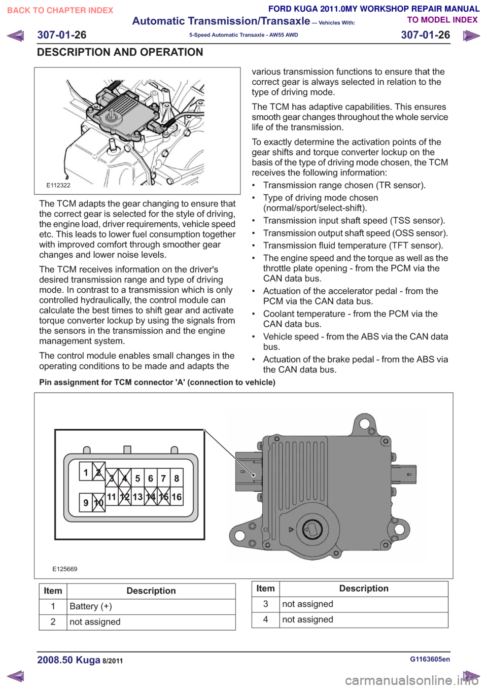
Pin assignment for TCM connector 'A' (connection to vehicle)
11
E125669
Description
Item
Battery (+)
1
not assigned
2Description
Item
not assigned
3
not assigned
4
G1163605en2008.50 Kuga8/2011
307-01- 26
Automatic Transmission/Transaxle
— Vehicles With:
5-Speed Automatic Transaxle - AW55 AWD
307-01- 26
DESCRIPTION AND OPERATION
TO MODEL INDEX
BACK TO CHAPTER INDEX
FORD KUGA 2011.0MY WORKSHOP REPAIR MANUAL
Page 1849 of 2057
21
22 20 19
15 14 13
161718 12
876
9
10
11 5
3
42121
22 20 19
15 14 13
161718 12
876
9
10
11 5
3
421
E125671
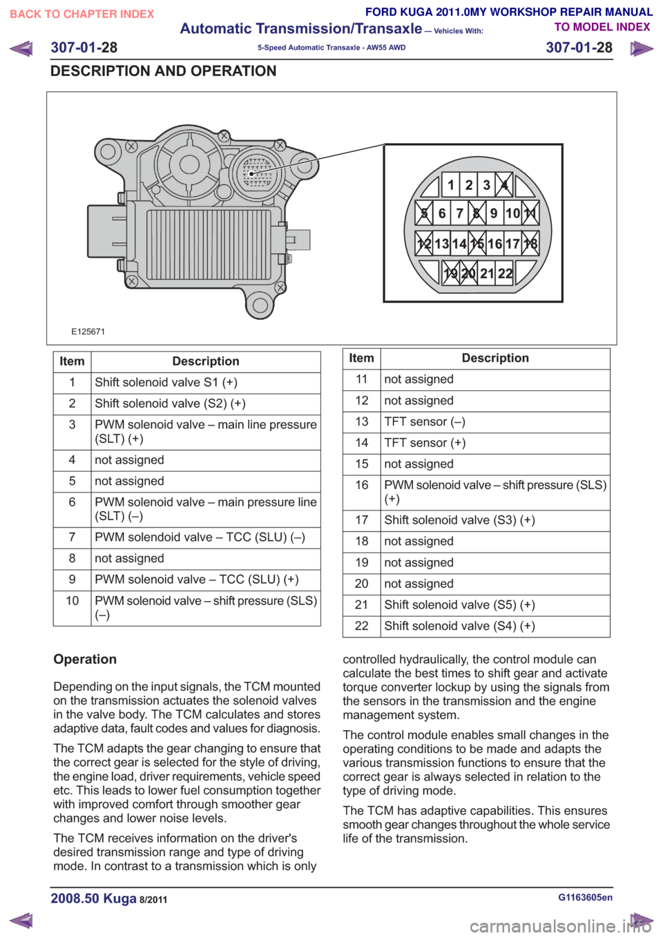
Description
Item
Shift solenoid valve S1 (+)
1
Shift solenoid valve (S2) (+)
2
PWM solenoid valve – main line pressure
(SLT) (+)
3
not assigned
4
not assigned
5
PWM solenoid valve – main pressure line
(SLT) (–)
6
PWM solendoid valve – TCC (SLU) (–)
7
not assigned
8
PWM solenoid valve – TCC (SLU) (+)
9
PWM solenoid valve – shift pressure (SLS)
(–)
10Description
Item
not assigned
11
not assigned
12
TFT sensor (–)
13
TFT sensor (+)
14
not assigned
15
PWM solenoid valve – shift pressure (SLS)
(+)
16
Shift solenoid valve (S3) (+)
17
not assigned
18
not assigned
19
not assigned
20
Shift solenoid valve (S5) (+)
21
Shift solenoid valve (S4) (+)
22
Operation
Depending on the input signals, the TCM mounted
on the transmission actuates the solenoid valves
in the valve body. The TCM calculates and stores
adaptive data, fault codes and values for diagnosis.
The TCM adapts the gear changing to ensure that
the correct gear is selected for the style of driving,
the engine load, driver requirements, vehicle speed
etc. This leads to lower fuel consumption together
with improved comfort through smoother gear
changes and lower noise levels.
The TCM receives information on the driver's
desired transmission range and type of driving
mode. In contrast to a transmission which is only controlled hydraulically, the control module can
calculate the best times to shift gear and activate
torque converter lockup by using the signals from
the sensors in the transmission and the engine
management system.
The control module enables small changes in the
operating conditions to be made and adapts the
various transmission functions to ensure that the
correct gear is always selected in relation to the
type of driving mode.
The TCM has adaptive capabilities. This ensures
smooth gear changes throughout the whole service
life of the transmission.
G1163605en2008.50 Kuga8/2011
307-01-
28
Automatic Transmission/Transaxle
— Vehicles With:
5-Speed Automatic Transaxle - AW55 AWD
307-01- 28
DESCRIPTION AND OPERATION
TO MODEL INDEX
BACK TO CHAPTER INDEX
FORD KUGA 2011.0MY WORKSHOP REPAIR MANUAL