climate control FORD KUGA 2011 1.G Service Manual
[x] Cancel search | Manufacturer: FORD, Model Year: 2011, Model line: KUGA, Model: FORD KUGA 2011 1.GPages: 2057
Page 171 of 2057
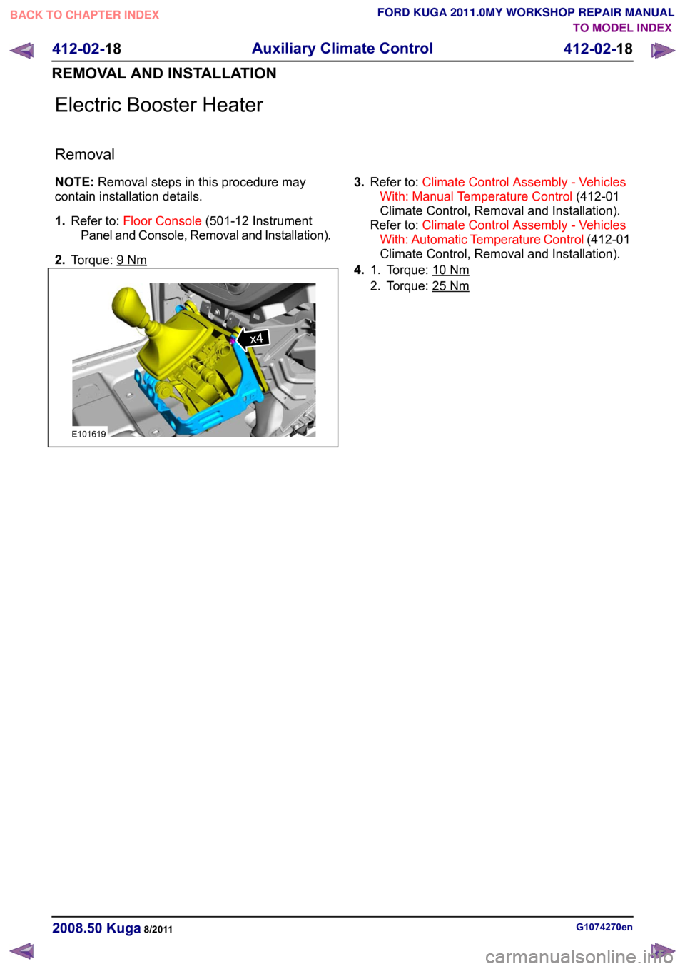
Electric Booster Heater
Removal
NOTE:
Removal steps in this procedure may
contain installation details.
1. Refer to: Floor Console (501-12 Instrument
Panel and Console, Removal and Installation).
2. Torque: 9 Nm 3.
Refer to: Climate Control Assembly - Vehicles
With: Manual Temperature Control (412-01
Climate Control, Removal and Installation).
Refer to: Climate Control Assembly - Vehicles
With: Automatic Temperature Control (412-01
Climate Control, Removal and Installation).
4. Torque: 10 Nm1.
2. Torque: 25
Nm
G1074270en
2008.50 Kuga 8/2011 412-02-18
Auxiliary Climate Control
412-02-18
REMOVAL AND INSTALLATIONTO MODEL INDEX
BACK TO CHAPTER INDEX
FORD KUGA 2011.0MY WORKSHOP REPAIR MANUALx4E101619
Page 173 of 2057
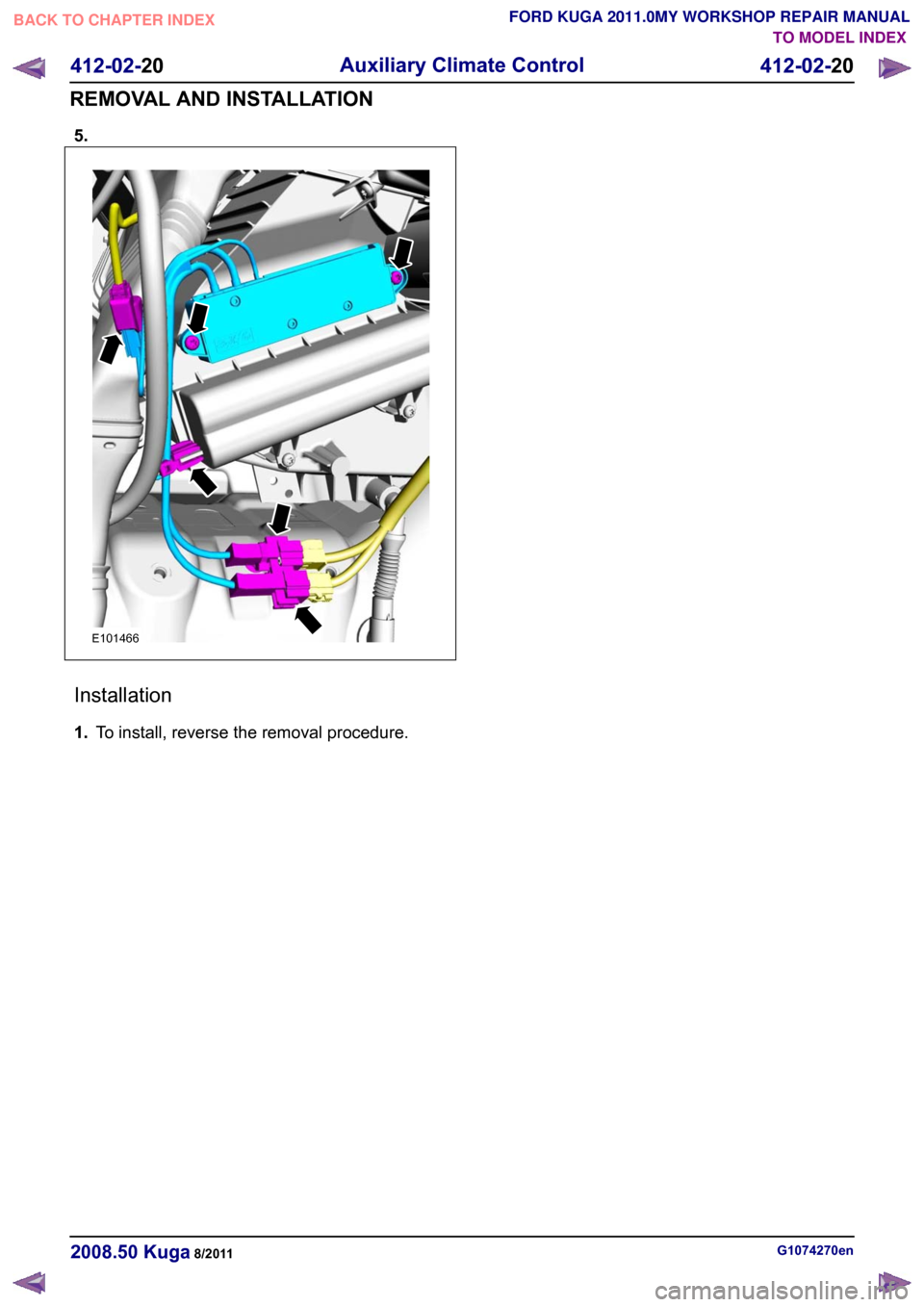
5.
Installation
1.
To install, reverse the removal procedure. G1074270en
2008.50 Kuga 8/2011 412-02-20
Auxiliary Climate Control
412-02-20
REMOVAL AND INSTALLATIONTO MODEL INDEX
BACK TO CHAPTER INDEX
FORD KUGA 2011.0MY WORKSHOP REPAIR MANUALE101466
Page 174 of 2057
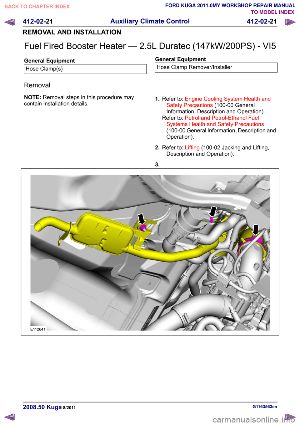
Fuel Fired Booster Heater — 2.5L Duratec (147kW/200PS) - VI5
General Equipment
Hose Clamp(s) General Equipment
Hose Clamp Remover/Installer
Removal
NOTE: Removal steps in this procedure may
contain installation details. 1.
Refer to: Engine Cooling System Health and
Safety Precautions (100-00 General
Information, Description and Operation).
Refer to: Petrol and Petrol-Ethanol Fuel
Systems Health and Safety Precautions
(100-00 General Information, Description and
Operation).
2. Refer to: Lifting(100-02 Jacking and Lifting,
Description and Operation).
3. G1163563en
2008.50 Kuga 8/2011 412-02-21
Auxiliary Climate Control
412-02-21
REMOVAL AND INSTALLATIONTO MODEL INDEX
BACK TO CHAPTER INDEX
FORD KUGA 2011.0MY WORKSHOP REPAIR MANUALE112641
Page 177 of 2057
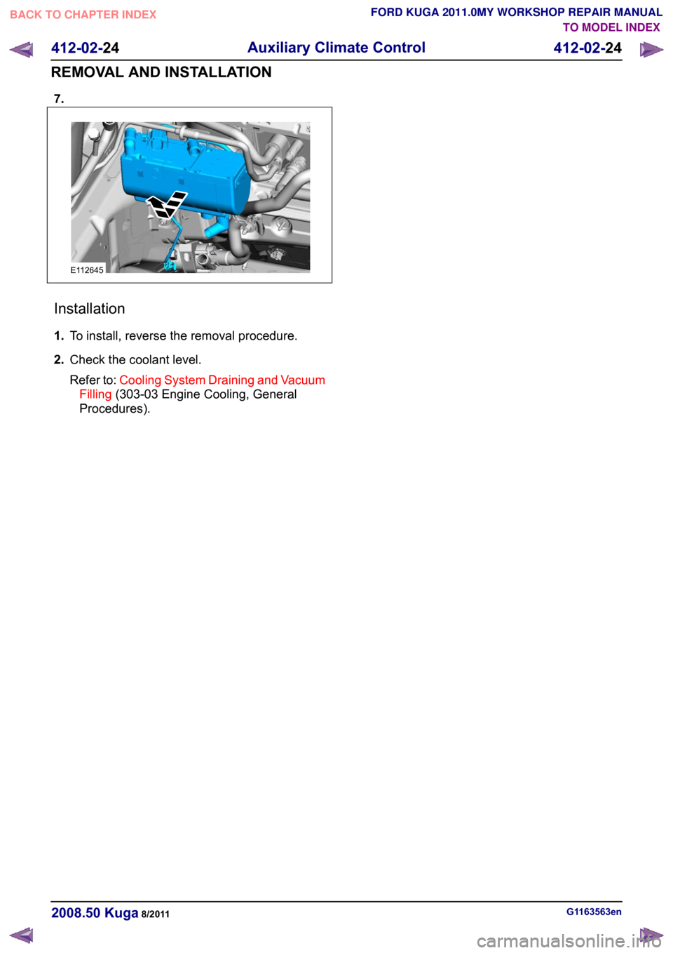
7.
Installation
1.
To install, reverse the removal procedure.
2. Check the coolant level.
Refer to: Cooling System Draining and Vacuum
Filling (303-03 Engine Cooling, General
Procedures). G1163563en
2008.50 Kuga 8/2011 412-02-24
Auxiliary Climate Control
412-02-24
REMOVAL AND INSTALLATIONTO MODEL INDEX
BACK TO CHAPTER INDEX
FORD KUGA 2011.0MY WORKSHOP REPAIR MANUALE112645
Page 178 of 2057
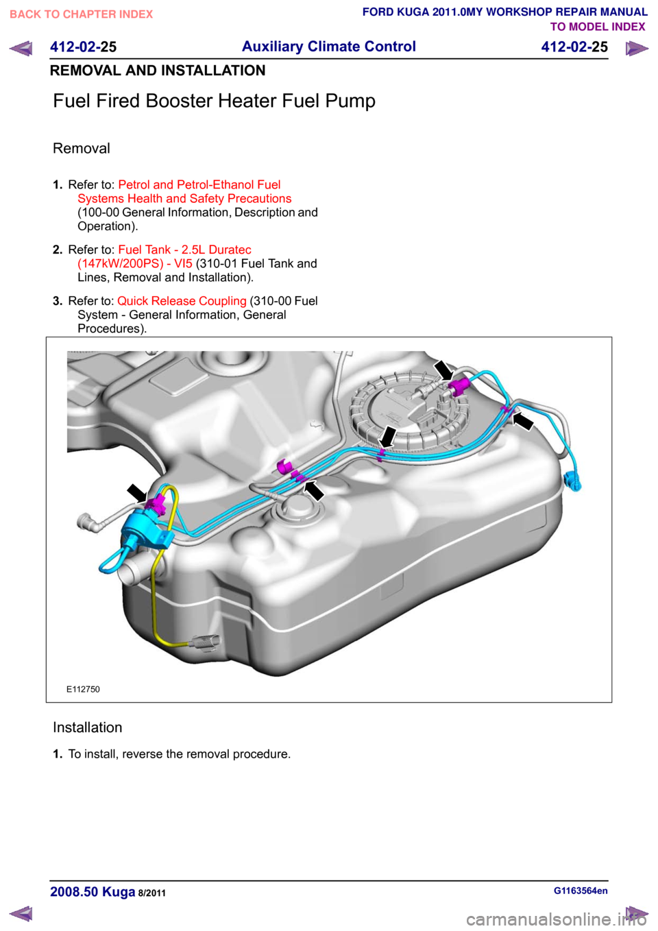
Fuel Fired Booster Heater Fuel Pump
Removal
1.
Refer to: Petrol and Petrol-Ethanol Fuel
Systems Health and Safety Precautions
(100-00 General Information, Description and
Operation).
2. Refer to: Fuel Tank - 2.5L Duratec
(147kW/200PS) - VI5 (310-01 Fuel Tank and
Lines, Removal and Installation).
3. Refer to: Quick Release Coupling (310-00 Fuel
System - General Information, General
Procedures). Installation
1.
To install, reverse the removal procedure. G1163564en
2008.50 Kuga 8/2011 412-02-25
Auxiliary Climate Control
412-02-25
REMOVAL AND INSTALLATIONTO MODEL INDEX
BACK TO CHAPTER INDEX
FORD KUGA 2011.0MY WORKSHOP REPAIR MANUALE112750
Page 179 of 2057
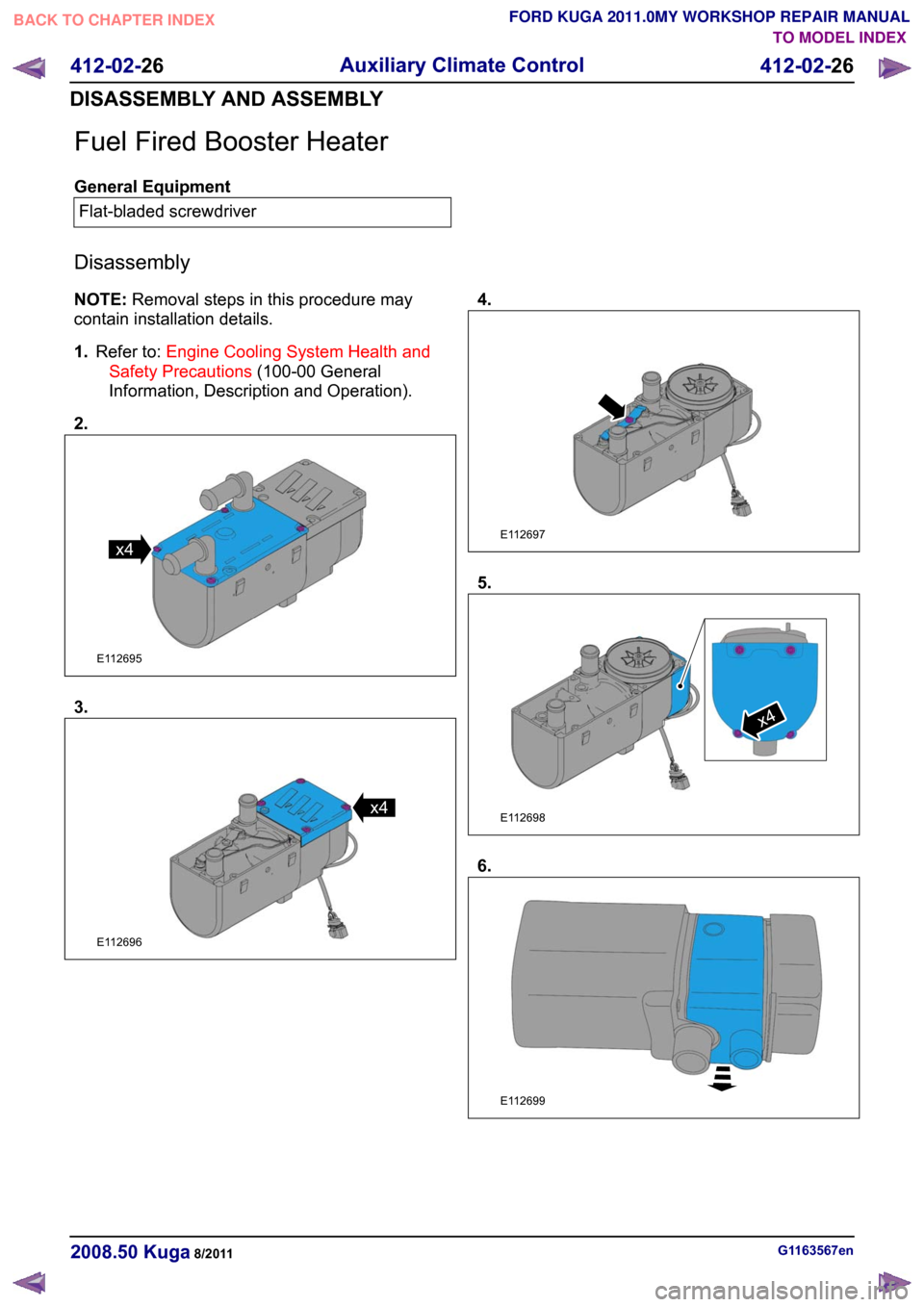
Fuel Fired Booster Heater
General Equipment
Flat-bladed screwdriver
Disassembly
NOTE: Removal steps in this procedure may
contain installation details.
1. Refer to: Engine Cooling System Health and
Safety Precautions (100-00 General
Information, Description and Operation).
2. 3. 4.
5.
6.
G1163567en
2008.50 Kuga 8/2011 412-02-26
Auxiliary Climate Control
412-02-26
DISASSEMBLY AND ASSEMBLYTO MODEL INDEX
BACK TO CHAPTER INDEX
FORD KUGA 2011.0MY WORKSHOP REPAIR MANUALx4E112695 E112696x4 E112697 E112698x4 E112699
Page 181 of 2057
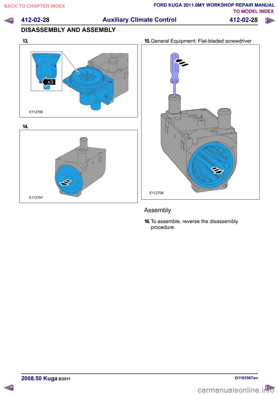
13.
14. 15.
General Equipment: Flat-bladed screwdriver Assembly
16.
To assemble, reverse the disassembly
procedure. G1163567en
2008.50 Kuga 8/2011 412-02-28
Auxiliary Climate Control
412-02-28
DISASSEMBLY AND ASSEMBLYTO MODEL INDEX
BACK TO CHAPTER INDEX
FORD KUGA 2011.0MY WORKSHOP REPAIR MANUALE112706x3 E112707 E112708
Page 183 of 2057
Instrument Cluster and Panel Illumination
Refer to
Wiring Diagrams Section 413-00, for
schematic and connector information.
Principles of Operation
NOTE: A new instrument cluster must be
configured.
The instrument cluster and panel illumination
consists of dimmable and non-dimmable
illumination. The dimmable panel illumination is
controlled by the panel illumination switch (part of
the headlamp switch), which allows the brightness
level of the backlights to be adjusted dependent
on the customer preference. When the headlamp
switch is in the parking lamps ON or headlamps
ON position, the intensity of the backlighting can
be adjusted using the panel dimmer switch. The
non dimmable illumination allows for full intensity
dependant on the ignition switch position.
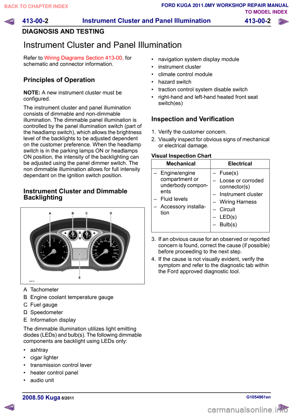
Instrument Cluster and Dimmable
Backlighting A.
Tachometer
B. Engine coolant temperature gauge
C. Fuel gauge
D. Speedometer
E. Information display
The dimmable illumination utilizes light emitting
diodes (LEDs) and bulb(s). The following dimmable
components are backlight using LEDs only:
• ashtray
• cigar lighter
• transmission control lever
• heater control panel
• audio unit • navigation system display module
• instrument cluster
• climate control module
• hazard switch
• traction control system disable switch
• right-hand and left-hand heated front seat
switch(es)
Inspection and Verification
1. Verify the customer concern.
2. Visually inspect for obvious signs of mechanical
or electrical damage.
Visual Inspection Chart Electrical
Mechanical
– Fuse(s)
– Loose or corrodedconnector(s)
– Instrument cluster
– Wiring Harness
– Circuit
– LED(s)
– Bulb(s)
– Engine/engine
compartment or
underbody compon-
ents
– Fluid levels
– Accessory installa- tion
3. If an obvious cause for an observed or reported concern is found, correct the cause (if possible)
before proceeding to the next step.
4. If the cause is not visually evident, verify the symptom and refer to the diagnostic tab within
the Ford approved diagnostic tool. G1054961en
2008.50 Kuga 8/2011 413-00-2
Instrument Cluster and Panel Illumination
413-00-2
DIAGNOSIS AND TESTINGTO MODEL INDEX
BACK TO CHAPTER INDEX
FORD KUGA 2011.0MY WORKSHOP REPAIR MANUALE98738ABCED
Page 451 of 2057
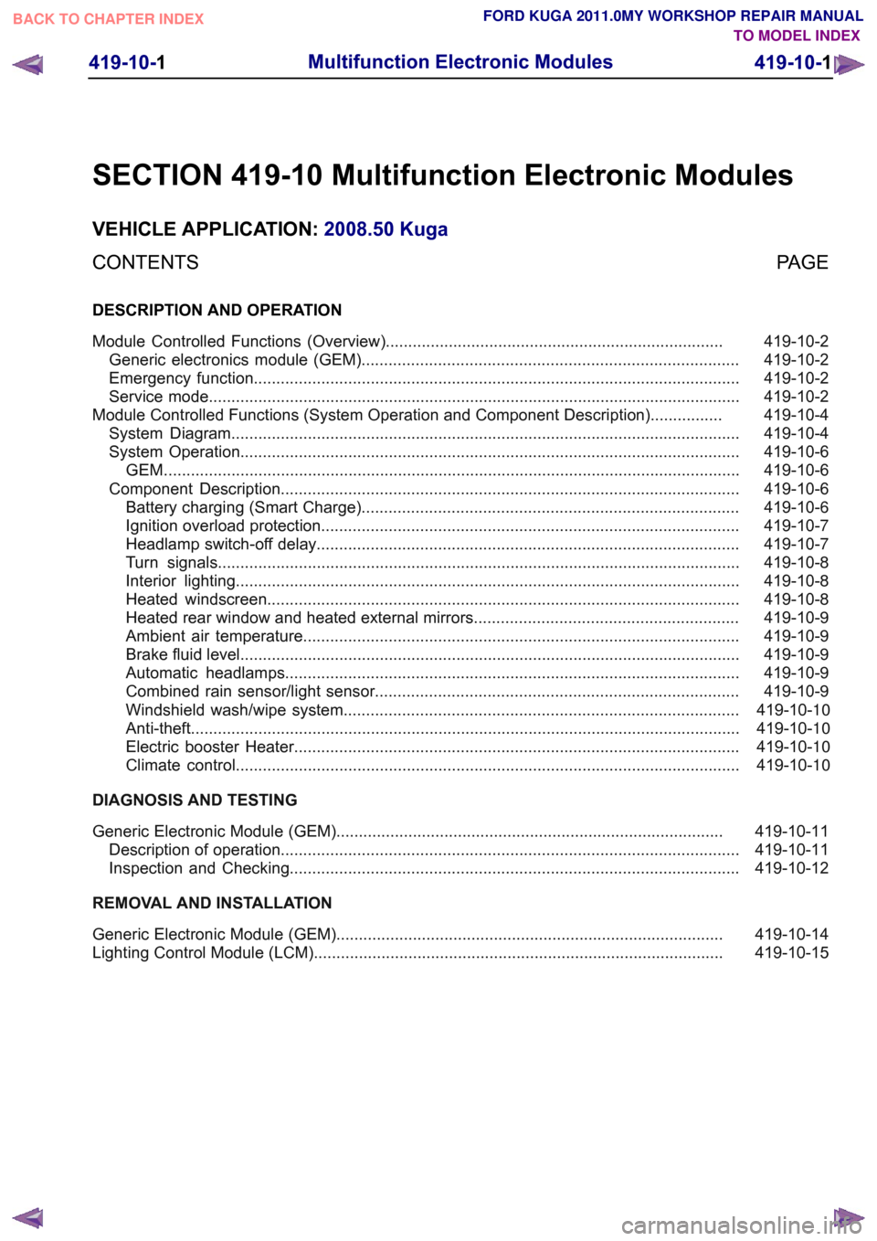
SECTION 419-10 Multifunction Electronic Modules
VEHICLE APPLICATION:
2008.50 Kuga
PAGE
CONTENTS
DESCRIPTION AND OPERATION
419-10-2
Module Controlled Functions (Overview)...........................................................................
419-10-2
Generic electronics module (GEM)....................................................................................
419-10-2
Emergency function............................................................................................................
419-10-2
Service mode......................................................................................................................
419-10-4
Module Controlled Functions (System Operation and Component Description)................
419-10-4
System Diagram.................................................................................................................
419-10-6
System Operation...............................................................................................................
419-10-6
GEM. ...............................................................................................................................
419-10-6
Component Description......................................................................................................
419-10-6
Battery charging (Smart Charge)....................................................................................
419-10-7
Ignition overload protection.............................................................................................
419-10-7
Headlamp switch-off delay..............................................................................................
419-10-8
Turn signals....................................................................................................................
419-10-8
Interior lighting................................................................................................................
419-10-8
Heated windscreen.........................................................................................................
419-10-9
Heated rear window and heated external mirrors...........................................................
419-10-9
Ambient air temperature.................................................................................................
419-10-9
Brake fluid level...............................................................................................................
419-10-9
Automatic headlamps.....................................................................................................
419-10-9
Combined rain sensor/light sensor.................................................................................419-10-10Windshield wash/wipe system........................................................................................
419-10-10Anti-theft ..........................................................................................................................
419-10-10Electric booster Heater...................................................................................................
419-10-10Climate control................................................................................................................
DIAGNOSIS AND TESTING 419-10-11
Generic Electronic Module (GEM)......................................................................................
419-10-11
Description of operation......................................................................................................
419-10-12
Inspection and Checking....................................................................................................
REMOVAL AND INSTALLATION 419-10-14
Generic Electronic Module (GEM)......................................................................................
419-10-15
Lighting Control Module (LCM)........................................................................................... 419-10-1
Multifunction Electronic Modules
419-10-1
.
TO MODEL INDEX
BACK TO CHAPTER INDEX
FORD KUGA 2011.0MY WORKSHOP REPAIR MANUAL
Page 456 of 2057
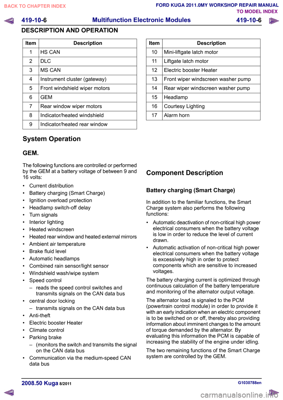
Description
Item
HS CAN
1
DLC2
MS CAN
3
Instrument cluster (gateway)
4
Front windshield wiper motors
5
GEM6
Rear window wiper motors
7
Indicator/heated windshield
8
Indicator/heated rear window
9 Description
Item
Mini-liftgate latch motor
10
Liftgate latch motor
11
Electric booster Heater
12
Front wiper windscreen washer pump
13
Rear wiper windscreen washer pump
14
Headlamp
15
Courtesy Lighting
16
Alarm horn
17
System Operation
GEM.
The following functions are controlled or performed
by the GEM at a battery voltage of between 9 and
16 volts:
• Current distribution
• Battery charging (Smart Charge)
• Ignition overload protection
• Headlamp switch-off delay
• Turn signals
• Interior lighting
• Heated windscreen
• Heated rear window and heated external mirrors
• Ambient air temperature
• Brake fluid level
• Automatic headlamps
• Combined rain sensor/light sensor
• Windshield wash/wipe system
• Speed control – reads the speed control switches andtransmits signals on the CAN data bus
• central door locking – transmits signals on the CAN data bus
• Anti-theft
• Electric booster Heater
• Climate control
• Parking brake –(monitors the switch and transmits the signal
on the CAN data bus
• Communication via the medium-speed CAN data bus Component Description
Battery charging (Smart Charge)
In addition to the familiar functions, the Smart
Charge system also performs the following
functions:
•
Automatic deactivation of non-critical high power
electrical consumers when the battery voltage
is low in order to reduce the level of current
drawn.
• Automatic activation of non-critical high power electrical consumers when the battery voltage
is excessively high in order to protect
components which are sensitive to increased
voltages.
The battery charging current is optimized through
continuous calculation of the battery temperature
and monitoring of the alternator output voltage.
The alternator load is signaled to the PCM
(powertrain control module) in order to provide it
with an early indication when an electric component
is to be switched on or off, thereby also providing
information about imminent changes to the amount
of torque demanded by the alternator. By
evaluating this information the PCM is capable of
increasing the stability of the engine under idling.
The two remaining functions of the Smart Charge
system are controlled by the GEM. G1030788en
2008.50 Kuga 8/2011 419-10-6
Multifunction Electronic Modules
419-10-6
DESCRIPTION AND OPERATIONTO MODEL INDEX
BACK TO CHAPTER INDEX
FORD KUGA 2011.0MY WORKSHOP REPAIR MANUAL