oil temperature FORD KUGA 2011 1.G Workshop Manual
[x] Cancel search | Manufacturer: FORD, Model Year: 2011, Model line: KUGA, Model: FORD KUGA 2011 1.GPages: 2057
Page 50 of 2057
foams should be conducted with extraction
ventilation. See also the vehicle Body Repair
Manual.
Freon
SeeAir Conditioning Refrigerant.
Fuels
See also, Fire, Legal Aspects, Chemicalsand
Solvents.
Avoid skin contact with fuel where possible. Should
contact occur, wash the affected skin with soap
and water.
Gasoline (Petrol)
Highly flammable - observe No Smoking policy.
For additional information, refer to: Petrol and
Petrol-Ethanol Fuel Systems Health and Safety
Precautions (100-00 General Information,
Description and Operation).
Gas-oil (Diesel Fuel)
Kerosene (Paraffin)
Used also as heating fuel, solvent and cleaning
agent.
Flammable - observe No Smoking policy.
Irritation of the mouth and throat may result from
swallowing. The main hazard from swallowing
arises if liquid aspiration into the lungs occurs.
Liquid contact dries the skin and can cause
irritation or dermatitis. Splashes in the eye may be
slightly irritating.
In normal circumstances the low volatility does not
give rise to harmful vapors. Exposure to mists and
vapors from kerosene at elevated temperature
should be avoided (mists may arise in dewaxing).
Avoid skin and eye contact and make sure there
is adequate ventilation.
Gas Cylinders
See also Fire. Gases such as oxygen, acetylene, argon and
propane are normally stored in cylinders at
pressures of up to 138 bar (2000 psi) and great
care should be taken in handling these cylinders
to avoid mechanical damage to them or to the valve
gear attached. The contents of each cylinder
should be clearly identified by appropriate
markings.
Cylinders should be stored in well-ventilated
enclosures, and protected from ice and snow, or
direct sunlight. Fuel gases, for example acetylene
and propane, should not be stored in close
proximity to oxygen cylinders.
Care should be exercised to prevent leaks from
gas cylinders and lines, and to avoid sources of
ignition.
Only trained personnel should undertake work
involving gas cylinders.
Gases
See
Gas Cylinders.
Gaskets (Fluoroelastomer)
SeeViton.
General Workshop Tools and
Equipment
It is essential that all tools and equipment are
maintained in good condition and that the correct
safety equipment is used where required.
Never use tools or equipment for any purpose other
than that for which they were designed. Never
overload equipment such as hoists, jacks, axle and
chassis stands or lifting slings. Damage caused by
overloading is not always immediately apparent
and may result in a fatal failure the next time that
the equipment is used.
Do not use damaged or defective tools or
equipment, particularly high-speed equipment such
as grinding wheels. A damaged grinding wheel can
disintegrate without warning and cause serious
injury.
Wear suitable eye protection when using grinding,
chiseling or sand blasting equipment.
Wear a suitable breathing mask when using
abrasive blasting equipment, working with
asbestos-based materials or using spraying
equipment.
G566527en2008.50 Kuga8/2011
100-00- 47
General Information
100-00- 47
DESCRIPTION AND OPERATION
TO MODEL INDEX
BACK TO CHAPTER INDEX
FORD KUGA 2011.0MY WORKSHOP REPAIR MANUAL
Page 63 of 2057
Road/Roller Testing
Road or roller testing may be carried out for various
reasons and a procedure detailing pre-test checks,
engine starting and stopping, pre-driving checks,
on-test checks and final checks to be completed
on completion of the test is given below.
Unless complete vehicle performance is being
checked, the full road test procedure need not be
carried out. Instead, those items particularly
relevant to the system(s) being checked can be
extracted.
Pre-Test Checks
WARNING: If the brake system hydraulic
fluid level is low, pedal travel is excessive
or a hydraulic leak is found, do not attempt
to road test the vehicle until the reason for
the low fluid level, excessive pedal travel
or hydraulic leak is found and rectified.
It is suggested that pre-test checks and functional
tests of those systems and circuits which affect the
safe and legal operations of the vehicle, such as
brakes, lights and steering, should always be
carried out before the road or roller test.
With the ignition switched off, check:
– the engine oil level.
– the engine coolant level.
– the tires, for correct pressure, compatible types and tread patterns, and wear within limits.
– that there is sufficient fuel in the tank to complete the test.
– all around the engine, transmission and under the vehicle for oil, coolant, hydraulic and fuel
leaks. Make a note of any apparent leaks and
wipe off the surrounding areas to make it easier
to identify the extent of the leak on completion
of the test.
Starting the Engine
NOTE: On initial drive away from cold and within
the first 1.5 km (1 mile), do not depress the
accelerator pedal beyond half travel until the
vehicle has attained a minimum speed of 25 km/h
(15 miles/h). Never operate at high engine speed
or with the accelerator pedal at full travel whilst the
engine is cold.
With the ignition switched off, check: – that the parking brake is applied.
– that the gear lever is in the neutral position.
– that all instrument gauges (except fuel gauge)
read zero.
With the ignition switched on, check:
– that the ignition controlled warning lamps are illuminated.
– that the engine temperature gauge registers a reading compatible with the engine temperature.
– that the fuel gauge registers a reading appropriate to the fuel level in the tank.
– the operation of the parking brake warning lamp and fluid level warning indicator.
Road or Roller Testing
CAUTION: If road testing, check the brake
operation while still traveling at low speed
before continuing with the test. If the
brakes pull to one side, or appear to be
otherwise faulty, do not continue with the
road test until the fault has been found and
rectified.
During the road or roller test, check:
– that the clutch pedal operation is not stiff or heavy.
– that the initial gear engagement is smooth and there is no evidence of clutch drag.
– that the parking brake control operates smoothly and releases quickly and completely.
– that the clutch takes up the drive smoothly, without slip or judder.
– that gear changing is smooth with no abnormal noises or vibrations from the transmission.
– the engine power output is satisfactory, full power is achieved, acceleration is smooth and
pedal operation is not stiff or heavy, and engine
speed returns to idle correctly.
– there is no excessive or abnormally colored smoke from the engine under normal driving,
heavy load or overrun conditions.
– that steering operation, including power steering (if equipped), is smooth, accurate, not
excessively heavy or with excessive free play
or vibration.
– that the steering does not pull to one side and self centers smoothly after cornering.
G17375en2008.50 Kuga8/2011
100-00- 58
General Information
100-00- 58
DESCRIPTION AND OPERATION
TO MODEL INDEX
BACK TO CHAPTER INDEX
FORD KUGA 2011.0MY WORKSHOP REPAIR MANUAL
Page 64 of 2057
– that the speedometer, coolant temperaturegauge and tachometer (if equipped) register the
correct readings and operate correctly.
– that the switches and controls operate smoothly and positively, warning and indicator lamps
operate correctly and the direction indicator
control self cancels when the steering is
returned to the straight ahead position.
– that the heating and ventilation systems operate correctly and effectively.
– the brake operation and efficiency.
Brake Testing
WARNING: When brake testing, avoid
breathing the fumes from hot brakes, this
may contain asbestos dust which is
hazardous to health. Failure to follow this
instruction may result in personal injury.
For additional information, refer to: Health
and Safety Precautions (100-00 General
Information, Description and Operation).
CAUTIONS:
Avoid brake testing on busy roads where
it may cause inconvenience or danger to
other road users.
Brake testing which includes heavy brake
applications should not be carried out with
new brake pads/discs or linings/drums
until the components have bedded-in. New
brake friction components will not reach
full efficiency until the bedding-in process
is complete.
Test the brakes at several speeds within the normal
operating range using both light and heavy pedal
pressure. Note any tendency to snatch, pull or
drag, and any undue delay in application or
release.
Allow the vehicle to coast and note any tendency
to pull to one side, or evidence that the brakes are
binding.
After stopping the vehicle (not immediately after a
period of heavy braking), carefully check the brake
temperature. A brake disc or brake drum that feels
hot or is appreciably hotter than the others,
indicates that the brake is binding.
After completion of the test, check for: – oil, coolant, hydraulic, air and fuel leaks.
– abnormal temperature of any moving
components or assemblies, for example wheel
hubs, transmission and axle, which might
indicate over tightness or lack of lubrication.
G17375en2008.50 Kuga8/2011
100-00- 59
General Information
100-00- 59
DESCRIPTION AND OPERATION
TO MODEL INDEX
BACK TO CHAPTER INDEX
FORD KUGA 2011.0MY WORKSHOP REPAIR MANUAL
Page 65 of 2057
Air Conditioning (A/C) System Health and Safety Precautions
WARNINGS:
Only qualified technicians are allowed to
work on air conditioning (A/C) systems.
Air conditioning (A/C) system components
can become particularly hot or cold.
Make sure that the air conditioning (A/C)
system is at ambient temperature before
carrying out any repair.
When handling refrigerants, always wear
protective goggles and gloves made of
fluoroelastomer. Leather or fabric gloves
are not suitable.
SKIN CONTACT: If liquid refrigerant comes
into contact with the skin, it produces
severe frostbite. Immediately flush affected
areas with plenty of cold running water for
15 minutes. Seek medical attention.
EYE CONTACT: If refrigerant comes into
contact with the eyes, immediately flush
the eyes with plenty of running water for
15 minutes. Seek medical attention.
INHALED: Toxic gases generated when
refrigerant is heated are hazardous to
health. The gases have an irritating smell
and can cause lung damage. The
symptoms can continue for a long time
after having been in contact with the gases.
The gases can cause lung damage even if
the amount of gas in the air is too small to
smell.
Refrigerant is flammable and explosive.
Make sure that refrigerant bottles are not
exposed to temperatures greater than 45°C.
Make sure that the local regulations
regarding work on air conditioning (A/C)
systems are adhered to.
Make sure that refrigerant bottles are
closed properly.
Gaseous refrigerant has a higher density
than air. There is a danger of suffocation
when working close to the ground or in
workshop pits.
Provide adequate ventilation when
handling refrigerant.
Never release refrigerant into the
atmosphere.
Only use special tools, equipment and
lubricants that are approved for the type
of refrigerant being used.
Always follow the manufacturer’s
instructions for the correct servicing unit
operating procedure.
CAUTIONS:
Do not mix refrigerant oils for different
types of refrigerant.
Never mix different types of refrigerant or
equipment intended for them.
Only use refrigerant in gas form when
filling the system through the low-pressure
connection.
Only use refrigerant in liquid form when
filling the system through the
high-pressure connection.
Refrigerant attacks certain plastics. Only
use seals suitable for refrigerant.
If the air conditioning (A/C) compressor is
damaged, the fixed orifice tube can
become blocked with metal particles.
Any sort of blockage in the refrigerant
circuit will damage the air conditioning
(A/C) compressor irreparably.
If the air conditioning (A/C) system has
been opened for a period greater than 2
hours, a new receiver drier must be
installed and the evacuating time to be
increased by a minimum of 2 hours.
NOTE: New air conditioning (A/C) compressors
are delivered prefilled.
NOTE: Refrigerant oil in new air conditioning (A/C)
compressors can contain Teflon, visible as white
particles, which will not harm the system.
G548993en2008.50 Kuga8/2011
100-00- 60
General Information
100-00- 60
DESCRIPTION AND OPERATION
TO MODEL INDEX
BACK TO CHAPTER INDEX
FORD KUGA 2011.0MY WORKSHOP REPAIR MANUAL
Page 187 of 2057
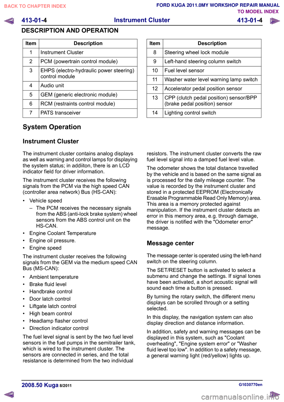
Description
Item
Instrument Cluster
1
PCM (powertrain control module)
2
EHPS (electro-hydraulic power steering)
control module
3
Audio unit
4
GEM (generic electronic module)
5
RCM (restraints control module)
6
PATS transceiver
7 Description
Item
Steering wheel lock module
8
Left-hand steering column switch
9
Fuel level sensor
10
Washer water level warning lamp switch
11
Accelerator pedal position sensor
12
CPP (clutch pedal position) sensor/BPP
(brake pedal position) sensor
13
Lighting control switch
14
System Operation
Instrument Cluster
The instrument cluster contains analog displays
as well as warning and control lamps for displaying
the system status; in addiiton, there is an LCD
indicator field for driver information.
The instrument cluster receives the following
signals from the PCM via the high speed CAN
(controller area network) Bus (HS-CAN):
• Vehicle speed – The PCM receives the necessary signalsfrom the ABS (anti-lock brake system) wheel
sensors from the ABS control unit on the
HS-CAN.
• Engine Coolant Temperature
• Engine oil pressure.
• Engine speed
The instrument cluster receives the following
signals from the GEM via the medium speed CAN
Bus (MS-CAN):
• Ambient temperature
• Brake fluid level
• Handbrake control
• Door latch control
• Liftgate latch control
• High beam control
• Headlamp flasher control
• Direction indicator control
The fuel level signal is sent by the two fuel level
sensors in the fuel pumps in the semitrailer tank,
which is wired to the instrument cluster. The
sensors are connected in series, and the total
resistance is determined from the two individual resistors. The instrument cluster converts the raw
fuel level signal into a damped fuel level value.
The odometer shows the total distance travelled
by the vehicle and is based on the same signal as
is processed for the daily mileage counter. The
value is recorded by the instrument cluster and
stored in a protected EEPROM (Electronically
Erasable Programmable Read Only Memory) area.
This area is a memory protected against
manipulation. If the instrument cluster detects an
error in this memory area, e.g. through damage,
the driver is notified with the "Odometer error"
message.
Message center
The message center is operated using the left-hand
switch on the steering column.
The SET/RESET button is activated to select a
submenu and change the settings. If signal tones
have been activated, a short acoustic signal will
sound each time a button is pressed.
By turning the rotary switch, the different menu
displays can be scrolled through or a setting
selected.
In this display, the navigation system can also
display direction and distance information.
In addition, safety and warning messages can be
displayed in this system, such as "Coolant
overheating", "Engine system error" or "Washer
fluid level too low". In addition to a safety message,
a general warning light (red/yellow) lights up.
G1030770en
2008.50 Kuga 8/2011 413-01-4
Instrument Cluster
413-01-4
DESCRIPTION AND OPERATIONTO MODEL INDEX
BACK TO CHAPTER INDEX
FORD KUGA 2011.0MY WORKSHOP REPAIR MANUAL
Page 190 of 2057
Instrument Cluster
Refer to
Wiring Diagrams Section 413-01, for
schematic and connector information. General Equipment
The Ford approved diagnostic tool
Inspection and Verification
1. Verify the customer concern.
2. Visually inspect for obvious signs of mechanical
or electrical damage.
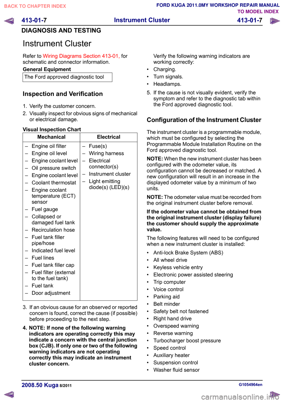
Visual Inspection Chart Electrical
Mechanical
– Fuse(s)
– Wiring harness
– Electricalconnector(s)
– Instrument cluster
– Light emitting diode(s) (LED)(s)
– Engine oil filter
– Engine oil level
–
Engine coolant level
– Oil pressure switch
– Engine coolant level
– Coolant thermostat
– Engine coolant temperature (ECT)
sensor
– Fuel gauge
– Collapsed or damaged fuel tank
– Recirculation hose
– Fuel tank filler pipe/hose
– Indicated fuel level
– Fuel lines
– Fuel tank filler cap
– Fuel filter (external to the fuel tank)
– Fuel tank
– Door adjustment
3. If an obvious cause for an observed or reported concern is found, correct the cause (if possible)
before proceeding to the next step.
4. NOTE: If none of the following warning indicators are operating correctly this may
indicate a concern with the central junction
box (CJB). If only one or two of the following
warning indicators are not operating
correctly this may indicate an instrument
cluster concern. Verify the following warning indicators are
working correctly:
• Charging.
• Turn signals.
• Headlamps.
5. If the cause is not visually evident, verify the symptom and refer to the diagnostic tab within
the Ford approved diagnostic tool.
Configuration of the Instrument Cluster
The instrument cluster is a programmable module,
which must be configured by selecting the
Programmable Module Installation Routine on the
Ford approved diagnostic tool.
NOTE: When the new instrument cluster has been
configured with the odometer value, its
configuration cannot be decreased or matched. A
new configuration will result in an increase in the
displayed odometer value by a minimum of two
units.
NOTE: The odometer value must be recorded from
the original instrument cluster before removal.
If the odometer value cannot be obtained from
the original instrument cluster (display failure)
the customer should supply the approximate
value.
The following features will need to be configured
when a new instrument cluster is installed:
• Anti-lock Brake System (ABS)
• All wheel drive
• Keyless vehicle entry
• Electronic power assisted steering
• Trip computer
• Voice control
• Parking aid
• Belt minder
• Safety belt not fastened
• Right hand drive
• Overspeed warning
• Reverse warning
• Turbocharger boost pressure
• Speed control
• Auxiliary heater
• Suspension control
• Washer fluid sensor G1054964en
2008.50 Kuga 8/2011 413-01-7
Instrument Cluster
413-01-7
DIAGNOSIS AND TESTINGTO MODEL INDEX
BACK TO CHAPTER INDEX
FORD KUGA 2011.0MY WORKSHOP REPAIR MANUAL
Page 1525 of 2057
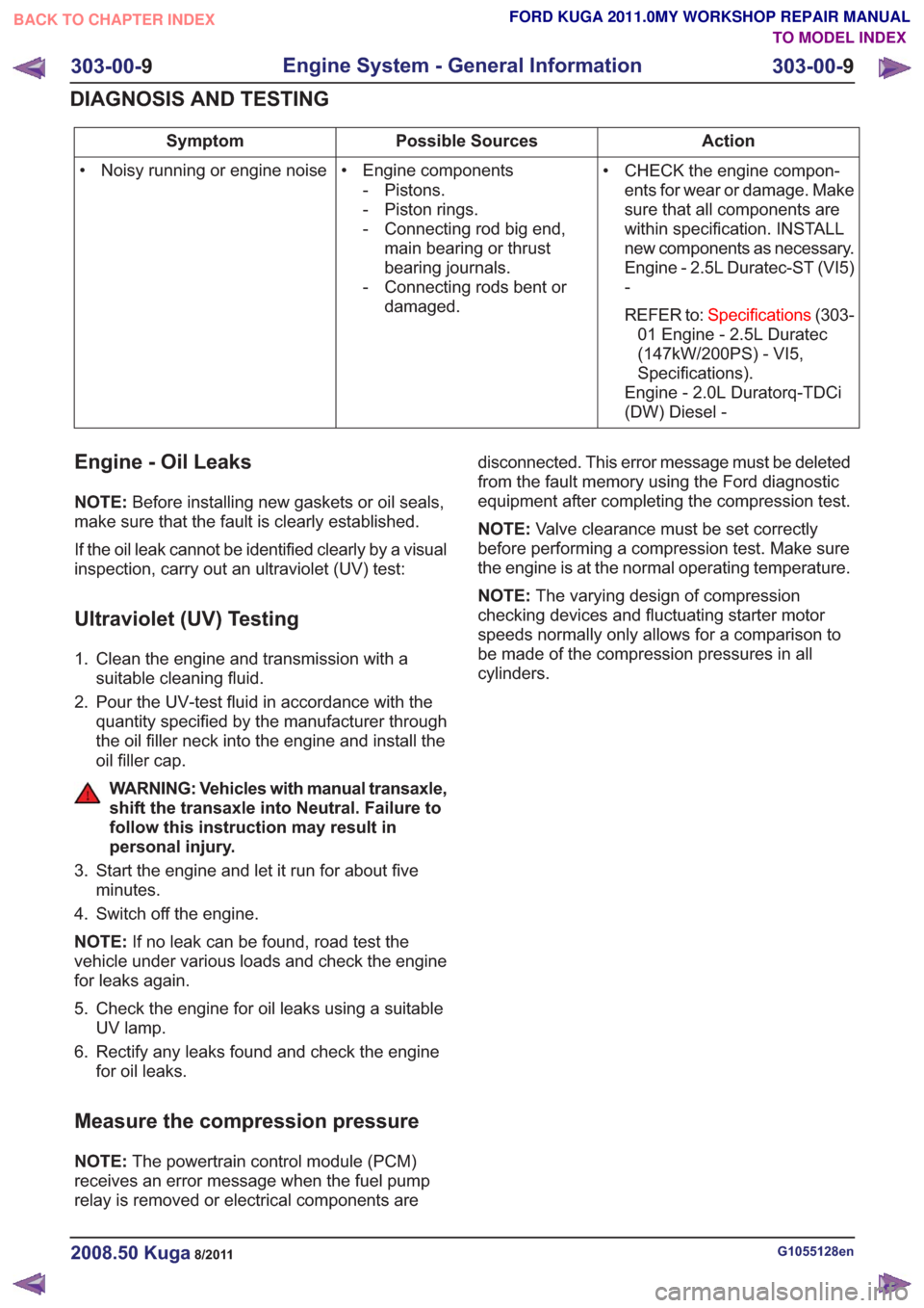
Action
Possible Sources
Symptom
• CHECK the engine compon-ents for wear or damage. Make
sure that all components are
within specification. INSTALL
new components as necessary.
Engine - 2.5L Duratec-ST (VI5)
-
REFER to: Specifications (303-
01 Engine - 2.5L Duratec
(147kW/200PS) - VI5,
Specifications).
Engine - 2.0L Duratorq-TDCi
(DW) Diesel -
• Engine components
- Pistons.
- Piston rings.
- Connecting rod big end,main bearing or thrust
bearing journals.
- Connecting rods bent or damaged.
• Noisy running or engine noise
Engine - Oil Leaks
NOTE:
Before installing new gaskets or oil seals,
make sure that the fault is clearly established.
If the oil leak cannot be identified clearly by a visual
inspection, carry out an ultraviolet (UV) test:
Ultraviolet (UV) Testing
1. Clean the engine and transmission with a suitable cleaning fluid.
2. Pour the UV-test fluid in accordance with the quantity specified by the manufacturer through
the oil filler neck into the engine and install the
oil filler cap.
WARNING: Vehicles with manual transaxle,
shift the transaxle into Neutral. Failure to
follow this instruction may result in
personal injury.
3. Start the engine and let it run for about five minutes.
4. Switch off the engine.
NOTE: If no leak can be found, road test the
vehicle under various loads and check the engine
for leaks again.
5. Check the engine for oil leaks using a suitable UV lamp.
6. Rectify any leaks found and check the engine for oil leaks.
Measure the compression pressure
NOTE: The powertrain control module (PCM)
receives an error message when the fuel pump
relay is removed or electrical components are disconnected. This error message must be deleted
from the fault memory using the Ford diagnostic
equipment after completing the compression test.
NOTE:
Valve clearance must be set correctly
before performing a compression test. Make sure
the engine is at the normal operating temperature.
NOTE: The varying design of compression
checking devices and fluctuating starter motor
speeds normally only allows for a comparison to
be made of the compression pressures in all
cylinders.
G1055128en2008.50 Kuga8/2011
303-00- 9
Engine System - General Information
303-00- 9
DIAGNOSIS AND TESTING
TO MODEL INDEX
BACK TO CHAPTER INDEX
FORD KUGA 2011.0MY WORKSHOP REPAIR MANUAL
Page 1527 of 2057
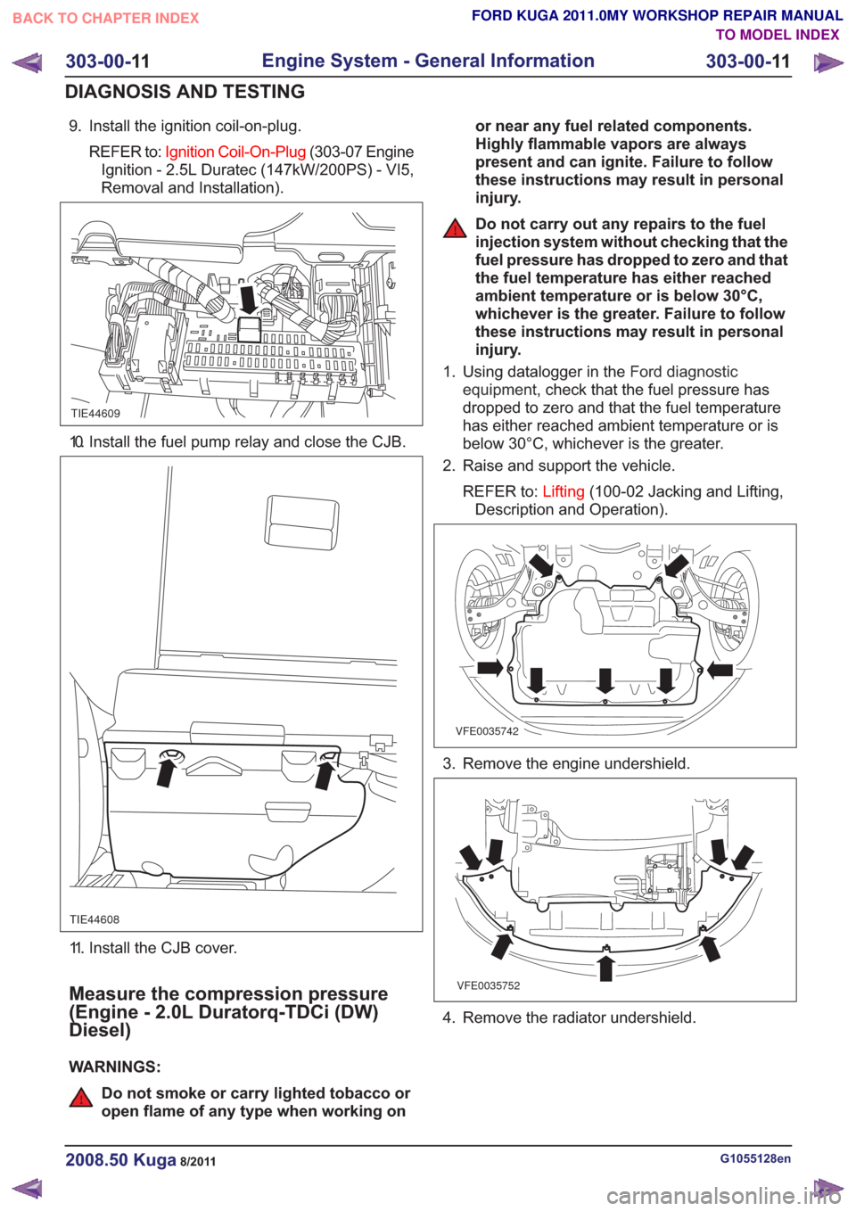
9. Install the ignition coil-on-plug.REFER to: Ignition Coil-On-Plug (303-07 Engine
Ignition - 2.5L Duratec (147kW/200PS) - VI5,
Removal and Installation).
TIE44609
10. Install the fuel pump relay and close the CJB.
TIE44608
11. Install the CJB cover.
Measure the compression pressure
(Engine - 2.0L Duratorq-TDCi (DW)
Diesel)
WARNINGS:
Do not smoke or carry lighted tobacco or
open flame of any type when working on or near any fuel related components.
Highly flammable vapors are always
present and can ignite. Failure to follow
these instructions may result in personal
injury.
Do not carry out any repairs to the fuel
injection system without checking that the
fuel pressure has dropped to zero and that
the fuel temperature has either reached
ambient temperature or is below 30°C,
whichever is the greater. Failure to follow
these instructions may result in personal
injury.
1. Using datalogger in the Ford diagnostic
equipment , check that the fuel pressure has
dropped to zero and that the fuel temperature
has either reached ambient temperature or is
below 30°C, whichever is the greater.
2. Raise and support the vehicle.
REFER to: Lifting(100-02 Jacking and Lifting,
Description and Operation).
VFE0035742
3. Remove the engine undershield.
VFE0035752
4. Remove the radiator undershield.
G1055128en2008.50 Kuga8/2011
303-00- 11
Engine System - General Information
303-00- 11
DIAGNOSIS AND TESTING
TO MODEL INDEX
BACK TO CHAPTER INDEX
FORD KUGA 2011.0MY WORKSHOP REPAIR MANUAL
Page 1530 of 2057
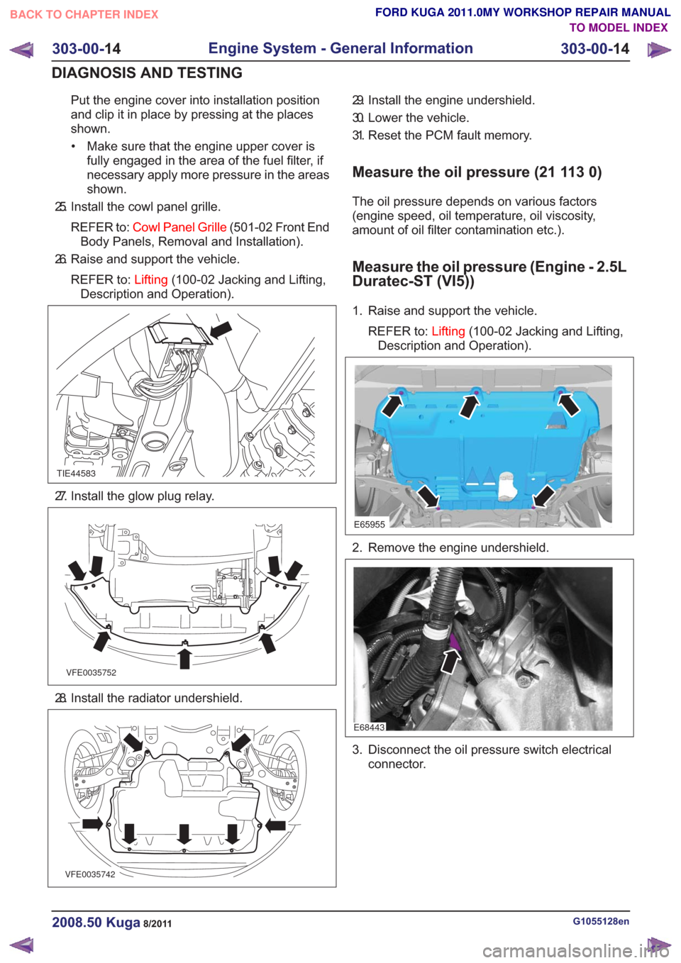
Put the engine cover into installation position
and clip it in place by pressing at the places
shown.• Make sure that the engine upper cover is fully engaged in the area of the fuel filter, if
necessary apply more pressure in the areas
shown.
25. Install the cowl panel grille.
REFER to: Cowl Panel Grille (501-02 Front End
Body Panels, Removal and Installation).
26. Raise and support the vehicle.
REFER to: Lifting(100-02 Jacking and Lifting,
Description and Operation).
TIE44583
27. Install the glow plug relay.
VFE0035752
28. Install the radiator undershield.
VFE0035742
29. Install the engine undershield.
30. Lower the vehicle.
31. Reset the PCM fault memory.
Measure the oil pressure (21 113 0)
The oil pressure depends on various factors
(engine speed, oil temperature, oil viscosity,
amount of oil filter contamination etc.).
Measure the oil pressure (Engine - 2.5L
Duratec-ST (VI5))
1. Raise and support the vehicle.
REFER to: Lifting(100-02 Jacking and Lifting,
Description and Operation).
E65955
2. Remove the engine undershield.
E68443
3. Disconnect the oil pressure switch electrical connector.
G1055128en2008.50 Kuga8/2011
303-00- 14
Engine System - General Information
303-00- 14
DIAGNOSIS AND TESTING
TO MODEL INDEX
BACK TO CHAPTER INDEX
FORD KUGA 2011.0MY WORKSHOP REPAIR MANUAL
Page 1531 of 2057
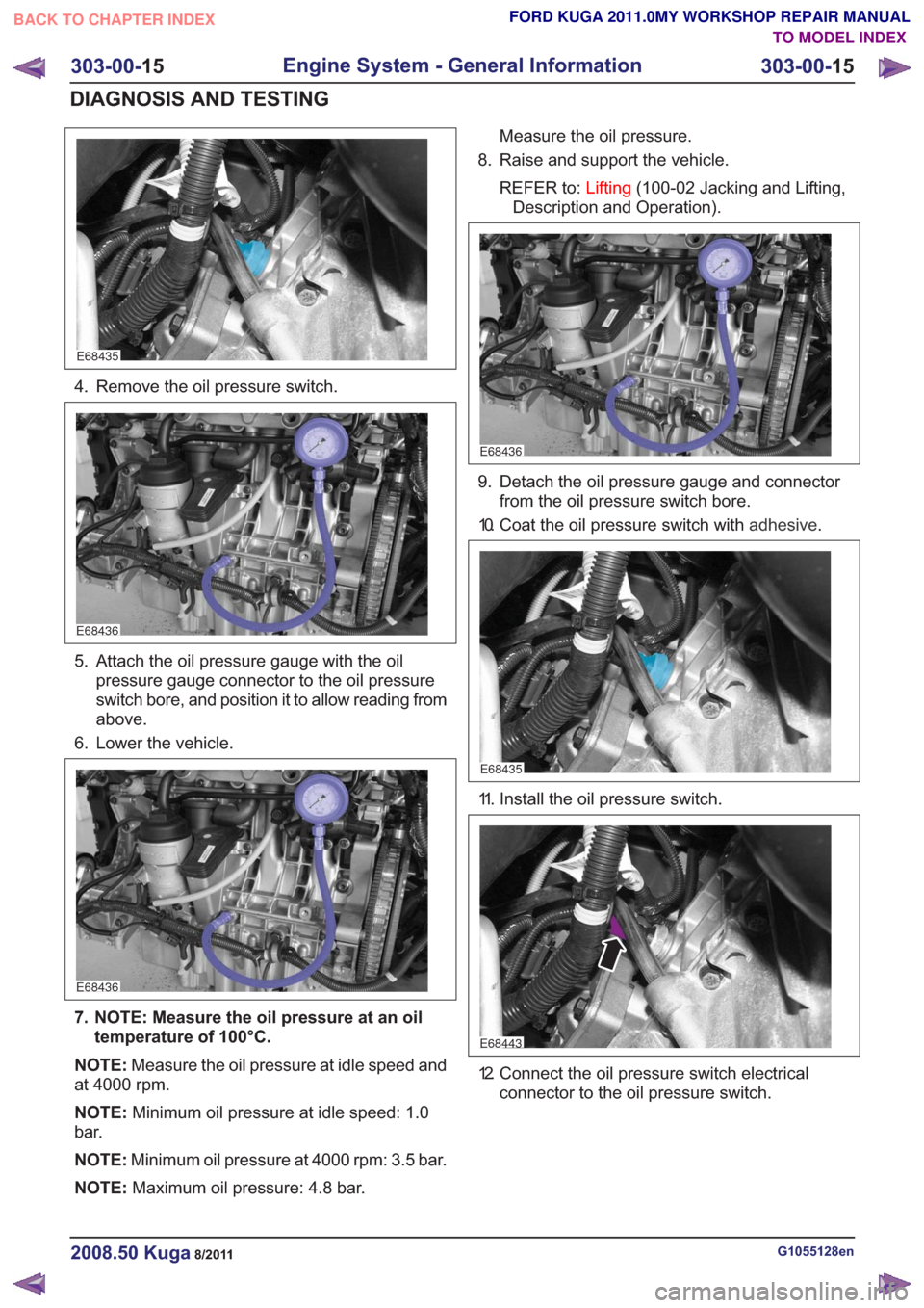
E68435
4. Remove the oil pressure switch.
E68436
5. Attach the oil pressure gauge with the oilpressure gauge connector to the oil pressure
switch bore, and position it to allow reading from
above.
6. Lower the vehicle.
E68436
7. NOTE: Measure the oil pressure at an oil temperature of 100°C.
NOTE: Measure the oil pressure at idle speed and
at 4000 rpm.
NOTE: Minimum oil pressure at idle speed: 1.0
bar.
NOTE: Minimum oil pressure at 4000 rpm: 3.5 bar.
NOTE: Maximum oil pressure: 4.8 bar. Measure the oil pressure.
8. Raise and support the vehicle.
REFER to: Lifting(100-02 Jacking and Lifting,
Description and Operation).
E68436
9. Detach the oil pressure gauge and connector from the oil pressure switch bore.
10. Coat the oil pressure switch with adhesive.
E68435
11. Install the oil pressure switch.
E68443
12. Connect the oil pressure switch electrical
connector to the oil pressure switch.
G1055128en2008.50 Kuga8/2011
303-00- 15
Engine System - General Information
303-00- 15
DIAGNOSIS AND TESTING
TO MODEL INDEX
BACK TO CHAPTER INDEX
FORD KUGA 2011.0MY WORKSHOP REPAIR MANUAL