diagram FORD KUGA 2011 1.G Service Manual
[x] Cancel search | Manufacturer: FORD, Model Year: 2011, Model line: KUGA, Model: FORD KUGA 2011 1.GPages: 2057
Page 1425 of 2057
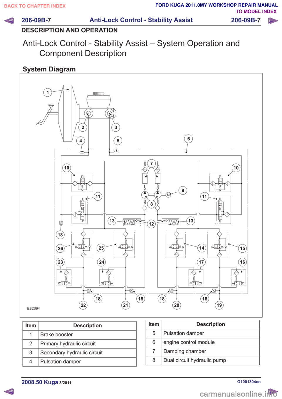
Anti-Lock Control - Stability Assist – System Operation andComponent Description
System Diagram
E82694
M
P
UP
U
P
U
P
U
P
U
1
10
22
23
456
7
8
9
11
1213
1415
1617
18
2324
13
11
10
19
2526
2120
181818
18
Description
Item
Brake booster
1
Primary hydraulic circuit
2
Secondary hydraulic circuit
3
Pulsation damper
4Description
Item
Pulsation damper
5
engine control module
6
Damping chamber
7
Dual circuit hydraulic pump
8
G1001304en2008.50 Kuga8/2011
206-09B- 7
Anti-Lock Control - Stability Assist
206-09B- 7
DESCRIPTION AND OPERATION
TO MODEL INDEX
BACK TO CHAPTER INDEX
FORD KUGA 2011.0MY WORKSHOP REPAIR MANUAL
Page 1458 of 2057
SECTION 211-02 Power Steering
VEHICLE APPLICATION:2008.50 Kuga
PA G E
CONTENTS
DESCRIPTION AND OPERATION
211-02-2
Power Steering (Component Location) ........................................................................\
......
211-02-3
Power Steering (Overview) ........................................................................\
.........................
211-02-3
Power Steering ........................................................................\
...........................................
211-02-4
Steering gear ........................................................................\
..............................................
211-02-5
Electro-hydraulic power steering pump ........................................................................\
......
211-02-6
Pressure and return lines ........................................................................\
...........................
211-02-7
Power Steering (System Operation and Component Description) .....................................
211-02-7
System Diagram ........................................................................\
.........................................
211-02-8
System Operation ........................................................................\
.......................................
211-02-8
Electronic principle of operation ........................................................................\
..............
211-02-9
Hydraulic principle of operation ........................................................................\
..............
211-02-9
Component Description ........................................................................\
..............................
211-02-9
Electro-hydraulic power steering pump ........................................................................\
..
211-02-10
Integrated steering angle sensor - vehicles built up to 09/2009 .....................................
211-02-11
Brushless DC motor with integral power steering module..............................................
REMOVAL AND INSTALLATION
211-02-13
(13 443 0)
Power Steering Pressure Line and Return Line Assembly — 2.5L Duratec
(147kW/200PS) - VI5 ........................................................................\
............
211-02-18
(13 434 0)
Power Steering Pump — 2.5L Duratec (147kW/200PS) - VI5 .......................
211-02-21
(13 440 0;
13 443 0)
Power Steering Pump to Steering Gear Pressure Line — 2.5L Duratec
(147kW/200PS) - VI5 ........................................................................\
............
211-02-25
(13 116 0)
Steering Gear ........................................................................\
.........................
211-02-36
(13 439 0)
Steering Gear to Power Steering Fluid Reservoir Return Line — 2.5L Duratec
(147kW/200PS) - VI5 ........................................................................\
............
211-02-1
Power Steering
211-02- 1
.
TO MODEL INDEX
BACK TO CHAPTER INDEX
FORD KUGA 2011.0MY WORKSHOP REPAIR MANUAL
Page 1464 of 2057
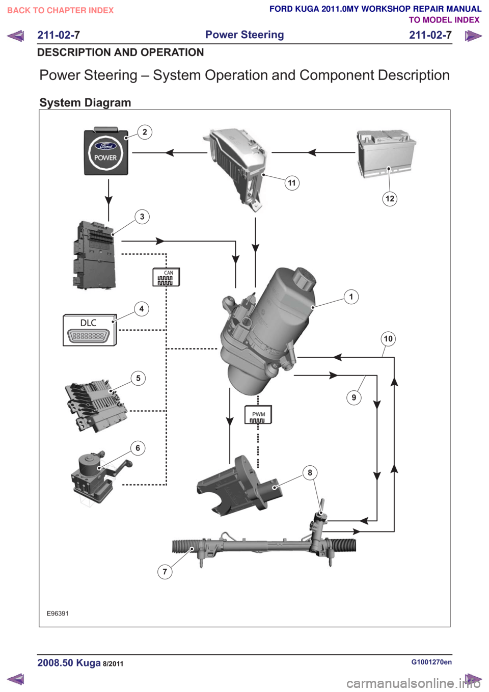
Power Steering – System Operation and Component Description
System Diagram
E96391
1
2
3
4
6
5
12
11
10
7
9
8
G1001270en2008.50 Kuga8/2011
211-02-7
Power Steering
211-02- 7
DESCRIPTION AND OPERATION
TO MODEL INDEX
BACK TO CHAPTER INDEX
FORD KUGA 2011.0MY WORKSHOP REPAIR MANUAL
Page 1695 of 2057
Fuel Charging and Controls
General EquipmentFord diagnostic equipment
Inspection and Verification
1. Verify the customer concern by operating the system.
2. Visually inspect for obvious signs of mechanical or electrical damage. Visual Inspection Chart
Electrical
Mechanical
– Loose or corrodedconnector(s)
– Wiring harness
– Fuel injector(s)
– Fuel leaks
– Blocked or contamin-
ated fuel filter
– Damaged fuel supply manifold
– Damaged fuel line connections
– Damaged vacuum hoses
– Fuel rail pressure sensor
3. If an obvious cause for an observed or reported concern is found, correct the cause (if possible)
before proceeding to the next step.
4. If the concern is not visually evident, verify the symptom and refer to the Ford diagnostic
equipment .
Symptom Chart
Action
Possible Sources
Symptom
• CHECK the PATS LED extin-guishes within 3 seconds when
the ignition is turned on.
REFER to: Anti-Theft - Passive
(419-01 Anti-Theft - Passive,
Diagnosis and Testing).
• PAT S .
• Engine does not crank
• REFER to:Starting System
(303-06 Starting System -
2.5L Duratec (147kW/200PS)
- VI5, Diagnosis and Testing).
• Starting system.
• REFER to the Wiring Diagrams.
• Ignition switch.
• Carry out a full enginediagnosis using the guided
diagnostic menu in the Ford
diagnostic equipment.
• Powertrain control module
(PCM).
• RESET the IFS switch.
• Inertia fuel shutoff (IFS) switch.
• Engine cranks but does not
start
• Check the fuel system pres-sure.
• Low fuel system pressure.
G1183441en2008.50 Kuga8/2011
303-04A-
4
Fuel Charging and Controls
— 2.5L Duratec (147kW/200PS) -
VI5
303-04A- 4
DIAGNOSIS AND TESTING
TO MODEL INDEX
BACK TO CHAPTER INDEX
FORD KUGA 2011.0MY WORKSHOP REPAIR MANUAL
Page 1717 of 2057
SECTION 303-04B Fuel Charging and Controls -
Turbocharger
— 2.5L Duratec (147kW/200PS) - VI5
VEHICLE APPLICATION:2008.50 Kuga
PA G E
CONTENTS
DESCRIPTION AND OPERATION
303-04B-2
Turbocharger (Component Location) ........................................................................\
..........
303-04B-4
Turbocharger (Overview) ........................................................................\
............................
303-04B-4
Turbocharger(s) ........................................................................\
..........................................
303-04B-5
Turbocharger (System Operation and Component Description) ........................................
303-04B-5
System Diagram ........................................................................\
.........................................
303-04B-6
System Operation ........................................................................\
.......................................
303-04B-6
Turbocharger(s) ........................................................................\
......................................
303-04B-6
Turbocharger boost pressure control ........................................................................\
......
303-04B-7
Recirculated air valve ........................................................................\
.............................
303-04B-7
Component Description ........................................................................\
..............................
303-04B-7
Wastegate control valve ........................................................................\
..........................
303-04B-7
Recirculated air valve ........................................................................\
.............................
DIAGNOSIS AND TESTING 303-04B-9
Turbocharger ........................................................................\
..............................................
303-04B-9
Inspection and Verification ........................................................................\
..........................
REMOVAL AND INSTALLATION 303-04B-11
(23 612 0)
Turbocharger ........................................................................\
..........................
303-04B-1
Fuel Charging and Controls - Turbocharger
—
2.5L Duratec (147kW/200PS) - VI5
303-04B- 1
.
TO MODEL INDEX
BACK TO CHAPTER INDEX
FORD KUGA 2011.0MY WORKSHOP REPAIR MANUAL
Page 1721 of 2057
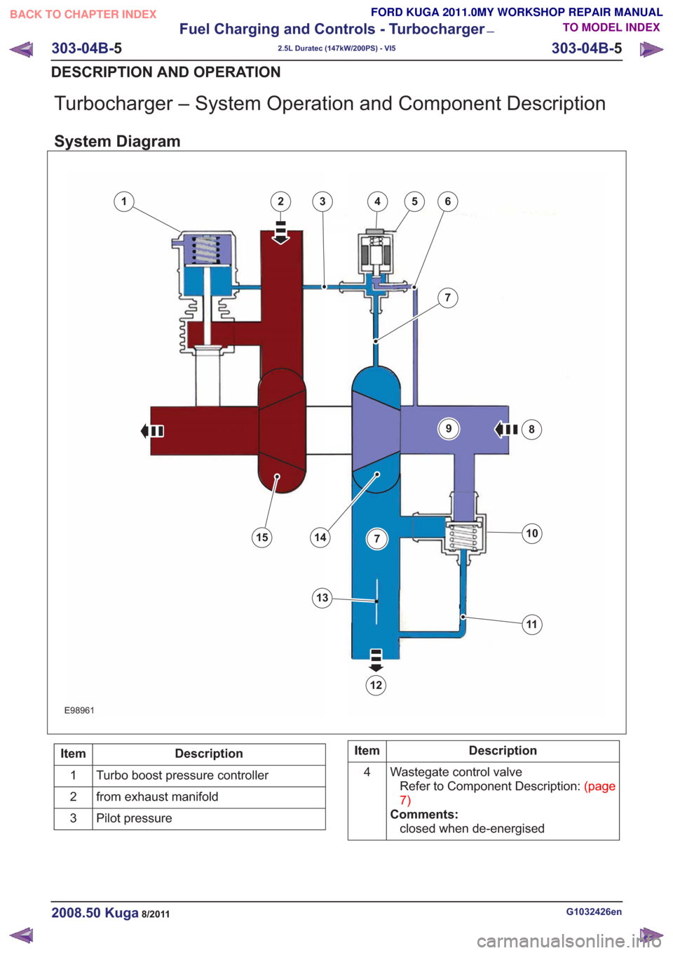
Turbocharger – System Operation and Component Description
System Diagram
346
7
8
10
11
12
1415
25
13
7
9
1346
7
8
10
11
12
1415
25
13
7
9
E98961
Description
Item
Turbo boost pressure controller
1
from exhaust manifold
2
Pilot pressure
3Description
Item
Wastegate control valveRefertoComponentDescription:(page
7)
Comments: closed when de-energised
4
G1032426en2008.50 Kuga8/2011
303-04B-
5
Fuel Charging and Controls - Turbocharger
—
2.5L Duratec (147kW/200PS) - VI5
303-04B- 5
DESCRIPTION AND OPERATION
TO MODEL INDEX
BACK TO CHAPTER INDEX
FORD KUGA 2011.0MY WORKSHOP REPAIR MANUAL
Page 1745 of 2057
SECTION 303-06 Starting System— 2.5L Duratec (147kW/200PS) - VI5
VEHICLE APPLICATION:2008.50 Kuga
PA G E
CONTENTS
DESCRIPTION AND OPERATION
303-06-2
Starting System (Component Location) ........................................................................\
......
303-06-3
Starting System (System Operation and Component Description) ....................................
303-06-3
System Diagram ........................................................................\
.........................................
303-06-8
System Operation ........................................................................\
.......................................
303-06-8
Smart Start ........................................................................\
..............................................
303-06-8
Emergency starting function ........................................................................\
...................
DIAGNOSIS AND TESTING 303-06-9
Starting System ........................................................................\
..........................................
303-06-9
Inspection and Verification ........................................................................\
..........................
REMOVAL AND INSTALLATION 303-06-10
(26 204 0)
Starter Motor ........................................................................\
...........................
303-06-11
Start Inhibit Switch ........................................................................\
......................................
303-06-1
Starting System— 2.5L Duratec (147kW/200PS) - VI5303-06-
1
.
TO MODEL INDEX
BACK TO CHAPTER INDEX
FORD KUGA 2011.0MY WORKSHOP REPAIR MANUAL
Page 1747 of 2057
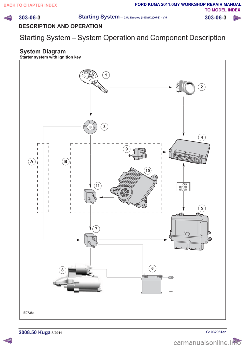
Starting System – System Operation and Component Description
System Diagram
Starter system with ignition key
E97384
1
2
4
6
5
8
9
10
11
3
BA
7
G1032961en2008.50 Kuga8/2011
303-06-3
Starting System— 2.5L Duratec (147kW/200PS) - VI5303-06-
3
DESCRIPTION AND OPERATION
TO MODEL INDEX
BACK TO CHAPTER INDEX
FORD KUGA 2011.0MY WORKSHOP REPAIR MANUAL
Page 1753 of 2057
Starting System
Refer toWiring Diagrams Section 303-06, for
schematic and connector information.
General Equipment
Ford diagnostic equipment
Inspection and Verification
1. Verify the customer concern.
2. Visually inspect for obvious signs of electrical damage.
Visual Inspection Chart
Electrical
• Fuse(s)
• Wiring harness
• Electrical connector(s)
• Relay
• Switch(es)
• Battery junction box (BJB)
• Engine junction box (EJB)
• Central junction box (CJB)
• Keyless vehicle module (KVM) (if equipped)
• Battery
• Starter motor
• Powertrain Control Module (PCM)
3. If an obvious cause for an observed or reported concern is found, correct the cause (if possible)
before proceeding to the next step.
4. If the cause is not visually evident, verify the symptom and refer to the diagnostictab within
the Ford diagnostic equipment .
G1183444en2008.50 Kuga8/2011
303-06-9
Starting System— 2.5L Duratec (147kW/200PS) - VI5303-06-
9
DIAGNOSIS AND TESTING
TO MODEL INDEX
BACK TO CHAPTER INDEX
FORD KUGA 2011.0MY WORKSHOP REPAIR MANUAL
Page 1775 of 2057
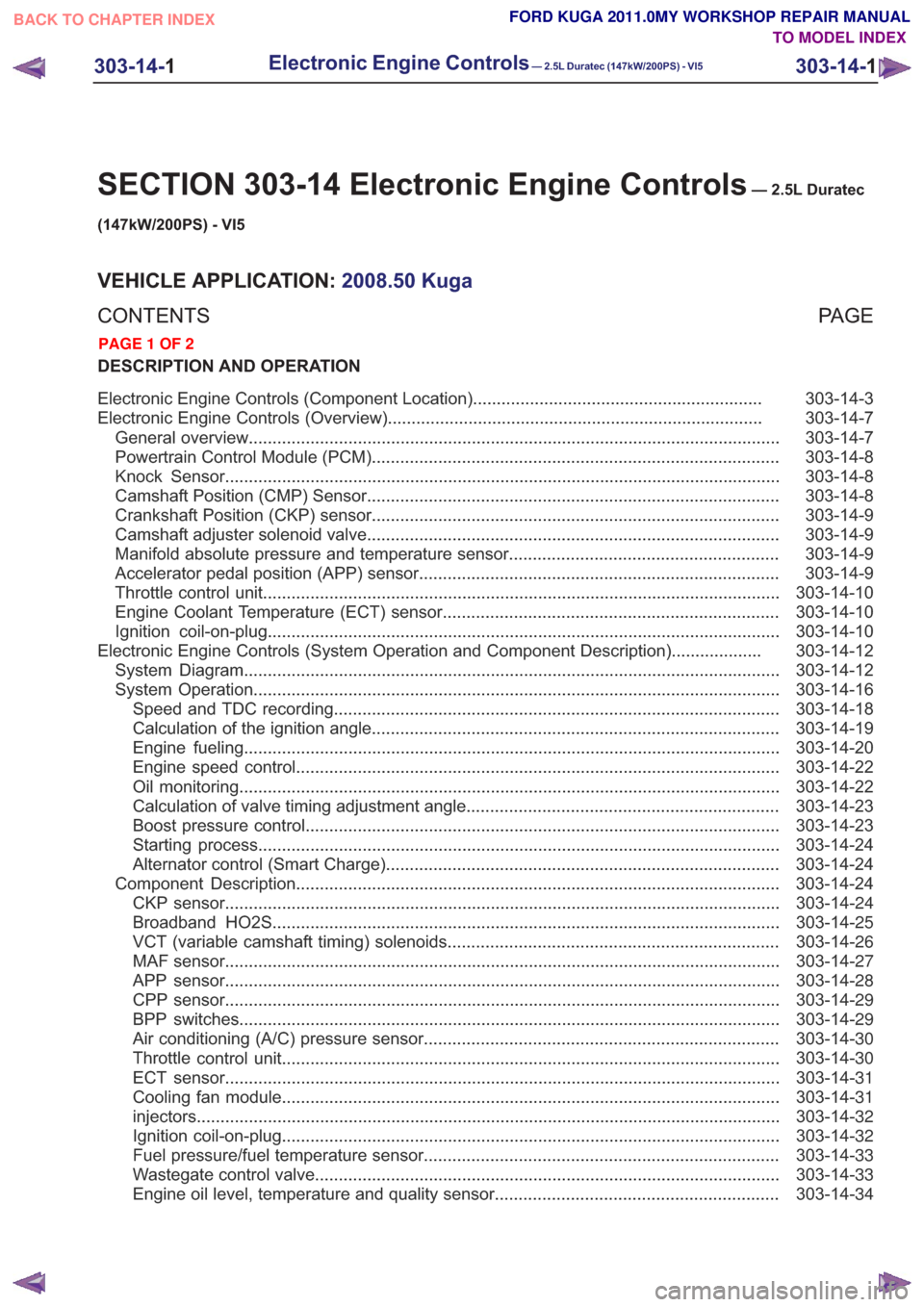
SECTION 303-14 Electronic Engine Controls— 2.5L Duratec
(147kW/200PS) - VI5
VEHICLE APPLICATION: 2008.50 Kuga
PA G E
CONTENTS
DESCRIPTION AND OPERATION
303-14-3
Electronic Engine Controls (Component Location) .............................................................
303-14-7
Electronic Engine Controls (Overview) ........................................................................\
.......
303-14-7
General overview ........................................................................\
........................................
303-14-8
Powertrain Control Module (PCM) ........................................................................\
..............
303-14-8
Knock Sensor ........................................................................\
.............................................
303-14-8
Camshaft Position (CMP) Sensor ........................................................................\
...............
303-14-9
Crankshaft Position (CKP) sensor ........................................................................\
..............
303-14-9
Camshaft adjuster solenoid valve........................................................................\
...............
303-14-9
Manifold absolute pressure and temperature sensor .........................................................
303-14-9
Accelerator pedal position (APP) sensor ........................................................................\
....
303-14-10
Throttle control unit ........................................................................\
.....................................
303-14-10
Engine Coolant Temperature (ECT) sensor.......................................................................
303-14-10
Ignition coil-on-plug ........................................................................\
....................................
303-14-12
Electronic Engine Controls (System Operation and Component Description) ...................
303-14-12
System Diagram ........................................................................\
.........................................
303-14-16
System Operation ........................................................................\
.......................................
303-14-18
Speed and TDC recording ........................................................................\
......................
303-14-19
Calculation of the ignition angle ........................................................................\
..............
303-14-20
Engine fueling ........................................................................\
.........................................
303-14-22
Engine speed control ........................................................................\
..............................
303-14-22
Oil monitoring ........................................................................\
..........................................
303-14-23
Calculation of valve timing adjustment angle..................................................................
303-14-23
Boost pressure control ........................................................................\
............................
303-14-24
Starting process ........................................................................\
......................................
303-14-24
Alternator control (Smart Charge) ........................................................................\
...........
303-14-24
Component Description ........................................................................\
..............................
303-14-24
CKP sensor ........................................................................\
.............................................
303-14-25
Broadband HO2S ........................................................................\
...................................
303-14-26
VCT (variable camshaft timing) solenoids ......................................................................
303-14-27
MAF sensor ........................................................................\
.............................................
303-14-28
APP sensor ........................................................................\
.............................................
303-14-29
CPP sensor ........................................................................\
.............................................
303-14-29
BPP switches ........................................................................\
..........................................
303-14-30
Air conditioning (A/C) pressure sensor ........................................................................\
...
303-14-30
Throttle
control unit ........................................................................\
.................................
303-14-31
ECT sensor ........................................................................\
.............................................
303-14-31
Cooling fan module ........................................................................\
.................................
303-14-32
injectors........................................................................\
...................................................
303-14-32
Ignition coil-on-plug ........................................................................\
.................................
303-14-33
Fuel pressure/fuel temperature sensor ........................................................................\
...
303-14-33
Wastegate control valve ........................................................................\
..........................
303-14-34
Engine oil level, temperature and quality sensor ............................................................
303-14-1
Electronic Engine Controls— 2.5L Duratec (147kW/200PS) - VI5303-14-
1
.
TO MODEL INDEX
BACK TO CHAPTER INDEX
PAGE 1 OF 2
FORD KUGA 2011.0MY WORKSHOP REPAIR MANUAL