gem module FORD KUGA 2011 1.G Repair Manual
[x] Cancel search | Manufacturer: FORD, Model Year: 2011, Model line: KUGA, Model: FORD KUGA 2011 1.GPages: 2057
Page 1795 of 2057
actuated) or opened (actuated). Each cylinder has
its own injector. The injection is accurately dosed
and takes place at a time determined by the PCM.
Injection takes place immediately in front of the
intake valves of the cylinder. The injectors are
actuated ground side via end-stages integrated
into the PCM and using the signal calculated by
the engine management system. Power is supplied
via the Powertrain Control Module relay in the BJB.
The injected fuel quantity depends on the opening
time, the fuel pressure and the diameter of the
nozzle holes.
The fuel metering is determined via open or
closed-loop control.
The open control loop differs from the closed
control loop in that the lambda control is
deactivated.
The PCM switches from closed to open-loop control
if the HO2S cools down to below 600°C or fails, as
well as when accelerating, coasting and at full load.
Regulation of injected fuel quantity via the PCM
involves:
• controlling the fuel pump,
• calculating the required quantity of fuel forengine starting,
• observance of the desired air/fuel ratio,
• calculating air mass,
• and calculating the fuel quantity for the different operating states and corresponding fuel
adjustment measures.
Open loop control
Open loop control is used primarily for fuel
injection, as long as the signals of the HO2S are
not involved in the calculation of the PCM.
The two most important reasons that make it
absolutely essential to run the engine without
lambda control (open-loop control) are the following
operating conditions:
• Cold engine (starting, warm-up phase)
• Full-load operation (WOT (wide open throttle))
Under these operating conditions the engine needs
a rich air/fuel mixture with lambda values below λ
= 1 in order to achieve optimum running or
optimum performance.
It is possible to keep this unregulated range very
small by using a broadband HO2S.
Closed-loop control
Closed loop control ensures strict control of
exhaust emissions in conjunction with the TWC (three-way catalytic converter) and economical fuel
consumption. With closed loop control, the signals
from the HO2S are analyzed by the PCM and the
engine always runs in the optimum range of λ = 1.
In addition to the normal HO2S, the signal from the
monitoring sensor for the catalytic converter is also
included in the control. The lambda control is
optimized on the basis of this data.
Certain factors such as wear, component
tolerances or more minor defects such as air leaks
in the intake system are compensated for by
lambda control. If the deviation occurs for a longer
period of time, this is recorded by the adaptive
(self-learning) function of lambda control. In this
instance, the entire map is shifted by the
corresponding amount, to enable control to
commence once again from the virtual baseline.
These adaptive settings are stored in the PCM and
are also used in open-loop control conditions.
If the adaptive value is too high or too low, an error
is stored in the fault memory of the PCM.
Oxygen sensor (HO2S) and catalyst monitor
sensor
A broadband HO2S is used as the HO2S. The
HO2S is located in front of the TWC. The catalyst
monitor sensor is located in the center of the TWC
so that it can detect any deterioration in the
cleaning performance of the TWC more quickly.
The HO2S measures the residual amount of
oxygen in the exhaust before the TWC.
The catalyst monitor sensor measures the amount
of oxygen in the exhaust gas after or in the TWC.
Both the HO2S and the catalyst monitor sensor
transmit these data to the PCM.
The broadband HO2S works at temperatures of
between 650°C and 900 °C. If the temperature
rises above 1000°C, the oxygen sensor will be
irreparably damaged.
To reach optimum operating temperature as quickly
as possible, an electrically-heated oxygen sensor
is installed. The heating also serves to maintain a
suitable operating temperature while coasting, for
example, when no hot gases are flowing past the
oxygen sensor.
The heating element in the HO2S is a PTC
(positive temperature coefficient) resistor. The
heating element is supplied with battery voltage as
soon as the Powertrain Control Module relay
engages. The HO2S is earthed via the PCM. As
the heating current is high when the element is
cold, it is limited via PWM in the PCM until a certain
G1021908en2008.50 Kuga8/2011
303-14-
21
Electronic Engine Controls— 2.5L Duratec (147kW/200PS) - VI5303-14-
21
DESCRIPTION AND OPERATION
TO MODEL INDEX
BACK TO CHAPTER INDEX
FORD KUGA 2011.0MY WORKSHOP REPAIR MANUAL
Page 1803 of 2057
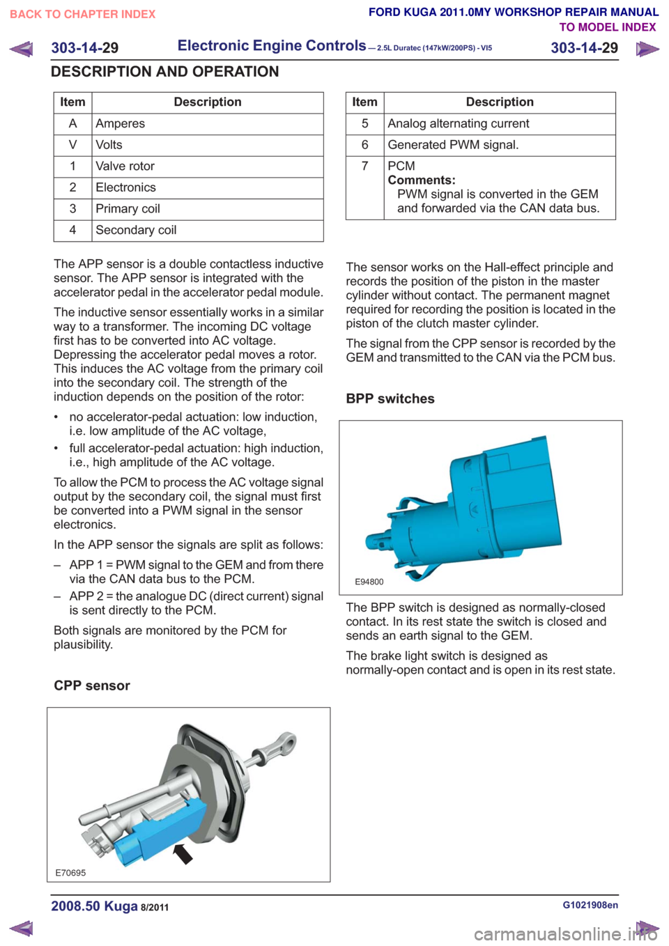
Description
Item
Amperes
A
Volts
V
Valve rotor
1
Electronics
2
Primary coil
3
Secondary coil
4Description
Item
Analog alternating current
5
Generated PWM signal.
6
PCM
Comments:PWM signal is converted in the GEM
and forwarded via the CAN data bus.
7
The APP sensor is a double contactless inductive
sensor. The APP sensor is integrated with the
accelerator pedal in the accelerator pedal module.
The inductive sensor essentially works in a similar
way to a transformer. The incoming DC voltage
first has to be converted into AC voltage.
Depressing the accelerator pedal moves a rotor.
This induces the AC voltage from the primary coil
into the secondary coil. The strength of the
induction depends on the position of the rotor:
• no accelerator-pedal actuation: low induction, i.e. low amplitude of the AC voltage,
• full accelerator-pedal actuation: high induction, i.e., high amplitude of the AC voltage.
To allow the PCM to process the AC voltage signal
output by the secondary coil, the signal must first
be converted into a PWM signal in the sensor
electronics.
In the APP sensor the signals are split as follows:
– APP 1 = PWM signal to the GEM and from there via the CAN data bus to the PCM.
– APP 2 = the analogue DC (direct current) signal is sent directly to the PCM.
Both signals are monitored by the PCM for
plausibility.
CPP sensor
E70695
The sensor works on the Hall-effect principle and
records the position of the piston in the master
cylinder without contact. The permanent magnet
required for recording the position is located in the
piston of the clutch master cylinder.
The signal from the CPP sensor is recorded by the
GEM and transmitted to the CAN via the PCM bus.
BPP switches
E94800
The BPP switch is designed as normally-closed
contact. In its rest state the switch is closed and
sends an earth signal to the GEM.
The brake light switch is designed as
normally-open contact and is open in its rest state.
G1021908en2008.50 Kuga8/2011
303-14- 29
Electronic Engine Controls— 2.5L Duratec (147kW/200PS) - VI5303-14-
29
DESCRIPTION AND OPERATION
TO MODEL INDEX
BACK TO CHAPTER INDEX
FORD KUGA 2011.0MY WORKSHOP REPAIR MANUAL
Page 1834 of 2057
E112805
59
13
2
6
10
14
3
7
11
15
4
8
12
16
17
19202118
1
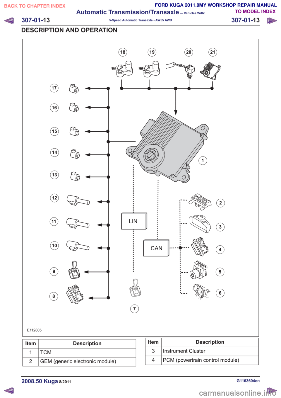
Description
Item
TCM1
GEM (generic electronic module)
2Description
Item
Instrument Cluster
3
PCM (powertrain control module)
4
G1163604en2008.50 Kuga8/2011
307-01- 13
Automatic Transmission/Transaxle
— Vehicles With:
5-Speed Automatic Transaxle - AW55 AWD
307-01- 13
DESCRIPTION AND OPERATION
TO MODEL INDEX
BACK TO CHAPTER INDEX
FORD KUGA 2011.0MY WORKSHOP REPAIR MANUAL
Page 1835 of 2057
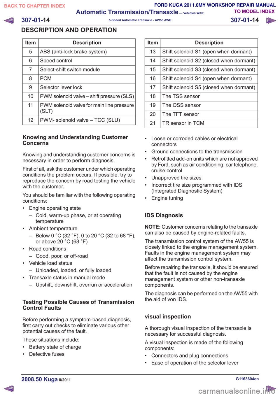
Description
Item
ABS (anti-lock brake system)
5
Speed control
6
Select-shift switch module
7
PCM
8
Selector lever lock
9
PWM solenoid valve – shift pressure (SLS)
10
PWM solenoid valve for main line pressure
(SLT)
11
PWM- solenoid valve – TCC (SLU)
12Description
Item
Shift solenoid S1 (open when dormant)
13
Shift solenoid S2 (closed when dormant)
14
Shift solenoid S3 (closed when dormant)
15
Shift solenoid S4 (open when dormant)
16
Shift solenoid S5 (closed when dormant)
17
The TSS sensor
18
The OSS sensor
19
The TFT sensor
20
TR sensor in TCM
21
Knowing and Understanding Customer
Concerns
Knowing and understanding customer concerns is
necessary in order to perform diagnosis.
First of all, ask the customer under which operating
conditions the problem occurs. If possible, try to
reproduce the concern by road testing the vehicle
with the customer.
You should be familiar with the following operating
conditions:
• Engine operating state
– Cold, warm-up phase, or at operatingtemperature
• Ambient temperature – Below 0 °C (32 °F), 0 to 20 °C (32 to 68 °F),or above 20 °C (68 °F)
• Road conditions – Good, poor, or off-road
• Vehicle load status – Unloaded, loaded, or fully loaded
• Transaxle status in manual mode – Upshift, downshift, overrun or acceleration
Testing Possible Causes of Transmission
Control Faults
Before performing a symptom-based diagnosis,
first carry out checks to eliminate various other
potential causes of the fault.
These situations include:
• Battery state of charge
• Defective fuses • Loose or corroded cables or electrical
connectors
• Ground connections to the transmission
• Retrofitted add-on units which are not approved by Ford, such as air conditioning, car telephone,
cruise control
• Unapproved tire sizes
• Incorrect tire size programmed with IDS (Integrated Diagnostic System)
• Engine tuning
IDS Diagnosis
NOTE: Customer concerns relating to the transaxle
can also be caused by engine-related faults.
The transmission control system of the AW55 is
closely linked to the engine management system.
Faults in the engine management system may
affect the transmission control system.
Before repairing the transaxle, it should be ensured
that the fault is not caused by the engine
management system or other non-transaxle
components.
The diagnosis can be performed on the AW55 with
the aid of von IDS.
visual inspection
A thorough visual inspection of the transaxle is
necessary for successful diagnosis.
A visual inspection is made of the following
components:
• Connectors and plug connections
• Ease of operation of the selector lever
G1163604en2008.50 Kuga8/2011
307-01- 14
Automatic Transmission/Transaxle
— Vehicles With:
5-Speed Automatic Transaxle - AW55 AWD
307-01- 14
DESCRIPTION AND OPERATION
TO MODEL INDEX
BACK TO CHAPTER INDEX
FORD KUGA 2011.0MY WORKSHOP REPAIR MANUAL
Page 1842 of 2057
Transmission Description – System Operation and ComponentDescription
System Operation
E112576
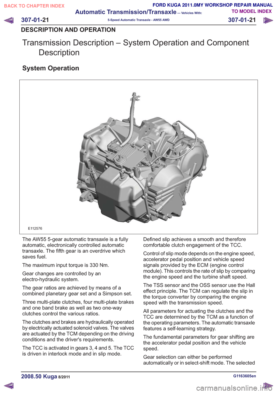
The AW55 5-gear automatic transaxle is a fully
automatic, electronically controlled automatic
transaxle. The fifth gear is an overdrive which
saves fuel.
The maximum input torque is 330 Nm.
Gear changes are controlled by an
electro-hydraulic system.
The gear ratios are achieved by means of a
combined planetary gear set and a Simpson set.
Three multi-plate clutches, four multi-plate brakes
and one band brake as well as two one-way
clutches control the various ratios.
The clutches and brakes are hydraulically operated
by electrically actuated solenoid valves. The valves
are actuated by the TCM depending on the driving
conditions and the driver's requirements.
The TCC is activated in gears 3, 4 and 5. The TCC
is driven in interlock mode and in slip mode. Defined slip achieves a smooth and therefore
comfortable clutch engagement of the TCC.
Control of slip mode depends on the engine speed,
accelerator pedal position and vehicle speed
signals provided by the ECM (engine control
module). This controls the rate of slip by comparing
the engine speed and the turbine shaft speed.
The TSS sensor and the OSS sensor use the Hall
effect principle. The TCM can regulate the slip in
the torque converter by comparing the engine
speed with the transmission speed.
All parameters for actuating the clutches and the
TCC are determined by the TCM as a function of
the operating parameters. The automatic transaxle
features a self-learning strategy.
The fundamental parameters for gear shifting are
the accelerator pedal position and the vehicle
speed.
Gear selection can either be performed
automatically or in select-shift mode. The selected
G1163605en2008.50 Kuga8/2011
307-01-
21
Automatic Transmission/Transaxle
— Vehicles With:
5-Speed Automatic Transaxle - AW55 AWD
307-01- 21
DESCRIPTION AND OPERATION
TO MODEL INDEX
BACK TO CHAPTER INDEX
FORD KUGA 2011.0MY WORKSHOP REPAIR MANUAL
Page 1847 of 2057
E112322
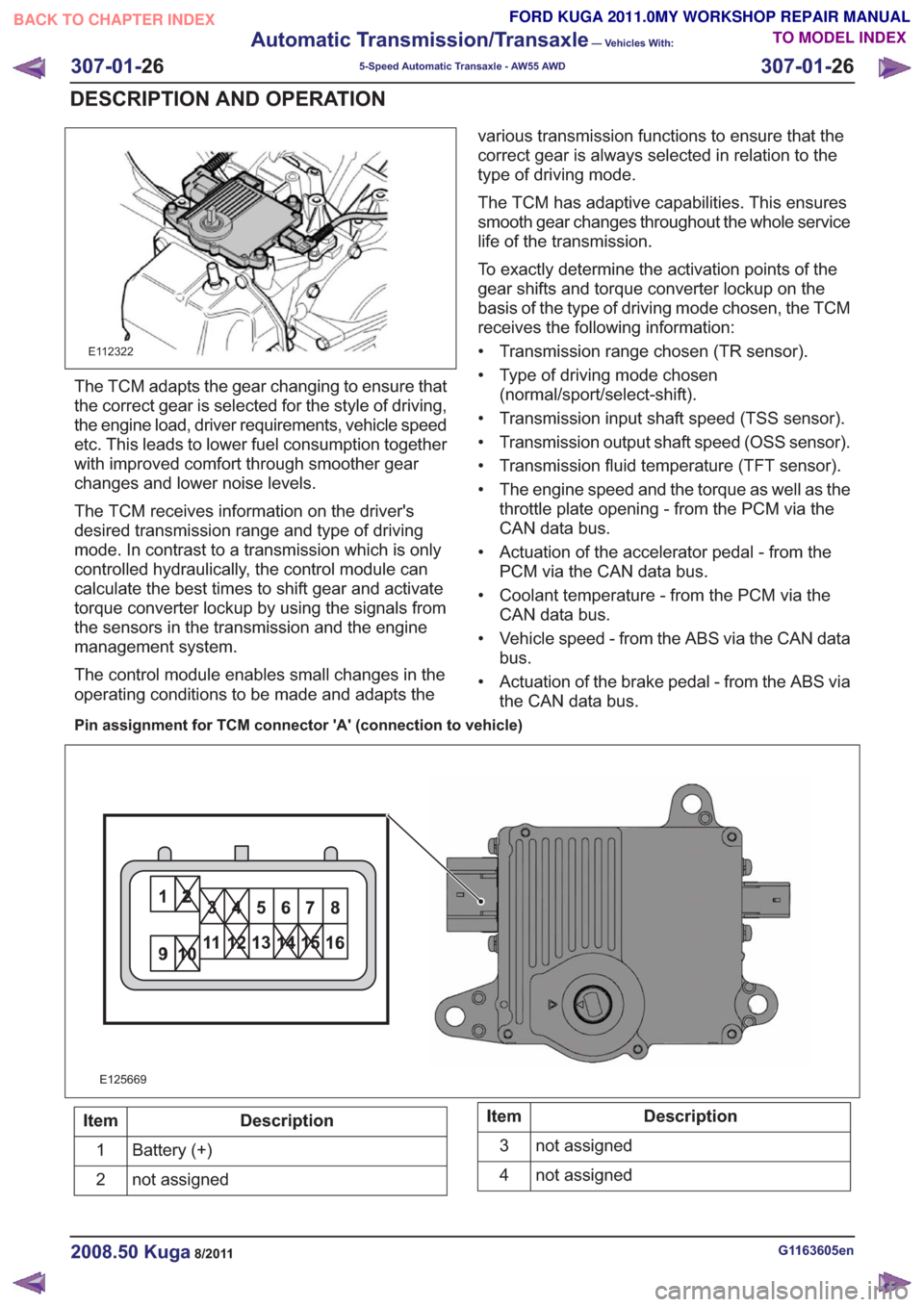
The TCM adapts the gear changing to ensure that
the correct gear is selected for the style of driving,
the engine load, driver requirements, vehicle speed
etc. This leads to lower fuel consumption together
with improved comfort through smoother gear
changes and lower noise levels.
The TCM receives information on the driver's
desired transmission range and type of driving
mode. In contrast to a transmission which is only
controlled hydraulically, the control module can
calculate the best times to shift gear and activate
torque converter lockup by using the signals from
the sensors in the transmission and the engine
management system.
The control module enables small changes in the
operating conditions to be made and adapts thevarious transmission functions to ensure that the
correct gear is always selected in relation to the
type of driving mode.
The TCM has adaptive capabilities. This ensures
smooth gear changes throughout the whole service
life of the transmission.
To exactly determine the activation points of the
gear shifts and torque converter lockup on the
basis of the type of driving mode chosen, the TCM
receives the following information:
• Transmission range chosen (TR sensor).
• Type of driving mode chosen
(normal/sport/select-shift).
• Transmission input shaft speed (TSS sensor).
• Transmission output shaft speed (OSS sensor).
• Transmission fluid temperature (TFT sensor).
• The engine speed and the torque as well as the throttle plate opening - from the PCM via the
CAN data bus.
• Actuation of the accelerator pedal - from the PCM via the CAN data bus.
• Coolant temperature - from the PCM via the CAN data bus.
• Vehicle speed - from the ABS via the CAN data bus.
• Actuation of the brake pedal - from the ABS via the CAN data bus.
Pin assignment for TCM connector 'A' (connection to vehicle)
11
E125669
Description
Item
Battery (+)
1
not assigned
2Description
Item
not assigned
3
not assigned
4
G1163605en2008.50 Kuga8/2011
307-01- 26
Automatic Transmission/Transaxle
— Vehicles With:
5-Speed Automatic Transaxle - AW55 AWD
307-01- 26
DESCRIPTION AND OPERATION
TO MODEL INDEX
BACK TO CHAPTER INDEX
FORD KUGA 2011.0MY WORKSHOP REPAIR MANUAL
Page 1849 of 2057
21
22 20 19
15 14 13
161718 12
876
9
10
11 5
3
42121
22 20 19
15 14 13
161718 12
876
9
10
11 5
3
421
E125671
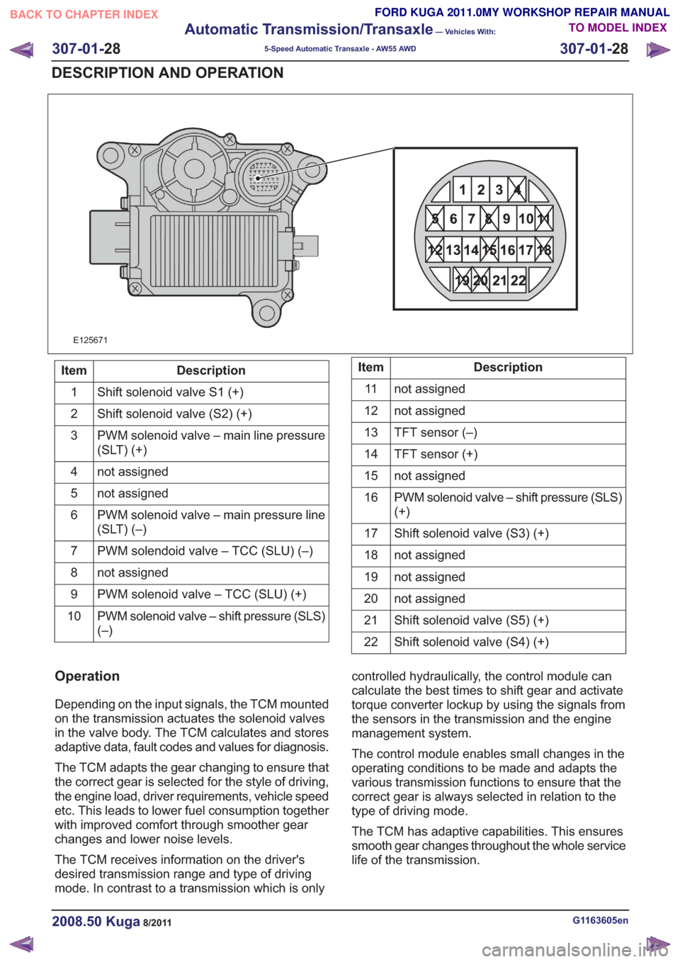
Description
Item
Shift solenoid valve S1 (+)
1
Shift solenoid valve (S2) (+)
2
PWM solenoid valve – main line pressure
(SLT) (+)
3
not assigned
4
not assigned
5
PWM solenoid valve – main pressure line
(SLT) (–)
6
PWM solendoid valve – TCC (SLU) (–)
7
not assigned
8
PWM solenoid valve – TCC (SLU) (+)
9
PWM solenoid valve – shift pressure (SLS)
(–)
10Description
Item
not assigned
11
not assigned
12
TFT sensor (–)
13
TFT sensor (+)
14
not assigned
15
PWM solenoid valve – shift pressure (SLS)
(+)
16
Shift solenoid valve (S3) (+)
17
not assigned
18
not assigned
19
not assigned
20
Shift solenoid valve (S5) (+)
21
Shift solenoid valve (S4) (+)
22
Operation
Depending on the input signals, the TCM mounted
on the transmission actuates the solenoid valves
in the valve body. The TCM calculates and stores
adaptive data, fault codes and values for diagnosis.
The TCM adapts the gear changing to ensure that
the correct gear is selected for the style of driving,
the engine load, driver requirements, vehicle speed
etc. This leads to lower fuel consumption together
with improved comfort through smoother gear
changes and lower noise levels.
The TCM receives information on the driver's
desired transmission range and type of driving
mode. In contrast to a transmission which is only controlled hydraulically, the control module can
calculate the best times to shift gear and activate
torque converter lockup by using the signals from
the sensors in the transmission and the engine
management system.
The control module enables small changes in the
operating conditions to be made and adapts the
various transmission functions to ensure that the
correct gear is always selected in relation to the
type of driving mode.
The TCM has adaptive capabilities. This ensures
smooth gear changes throughout the whole service
life of the transmission.
G1163605en2008.50 Kuga8/2011
307-01-
28
Automatic Transmission/Transaxle
— Vehicles With:
5-Speed Automatic Transaxle - AW55 AWD
307-01- 28
DESCRIPTION AND OPERATION
TO MODEL INDEX
BACK TO CHAPTER INDEX
FORD KUGA 2011.0MY WORKSHOP REPAIR MANUAL
Page 1850 of 2057
To exactly determine the activation points of the
gear shifts and torque converter lockup on the
basis of the type of driving mode chosen, the TCM
receives the following information:
• Selected transmission range (TR sensor)
• Selected driving mode (normal/sport/select-shift)
• Transmission input shaft speed (TSS sensor)
• Transmission output shaft speed (OSS sensor)
• Transmission fluid temperature (TFT sensor)
• The engine speed and the torque as well as thethrottle plate opening - from the PCM via the
CAN databus
• Actuation of accelerator – from the PCM via the CAN databus
• The coolant temperature – from the PCM via the CAN databus
• Road speed – from the ABS module via the CAN databus
• Actuation of brake pedal – from the PCM via the CAN databus
Gearshift control
Adaptation
The TCM monitors every shift operation in all
driving conditions to make even and smooth gear
shifts possible. This is done by the control module,
which either lowers or increases the hydraulic line
pressure during gearshifts.
The changed pressure values are stored in the
control module memory after the engine is switched
off and retrieved during engine starting. This
improves the shift comfort and extends the service
life.
Full adaptability occurs when the following criteria
are met:
• Throttle plate opening is constant.
• Transmission fluid temperature between 65 °Cand 110 °C.
Shifting from 'P' to another transmission
range
To be able to move the selector lever from 'P' into
another transmission range, the ignition must be
switched on and the brake pedal pressed (stoplamp
switch on). The TCM detects the position of the
brake pedal via the CAN data bus and the engaged
transmission range from the TR sensor. Based on this information, the TCM transmits a
signal to the select-shift switch module. This
activates the brake shift interlock actuator in the
selector lever assembly.
When the brake shift interlock actuator is activated,
the locking pin is retracted so that another
transmission range can be selected.
The brake shift interlock actuator is deactivated
when the ignition is switched off. It is mechanically
locked when the gear selector lever is in 'P'.
Automatic transmission, selector lever in
position "D".
The TCM adapts the shift points to match the
driving conditions. Normally the TCM is in adaptive
mode and gear changes take place adapted to the
driving conditions. If special driving conditions are
detected, the TCM switches to predefined
characteristics.
When driving with normal acceleration, the TCM
uses a preset shift program which is optimized for
economical driving.
This shift program is suitable for "normal" driving
and delivers early upward changes and torque
converter lockup. Furthermore, the transmission
fluid pressure is adapted to make smooth
engagement of the gears possible.
Sport mode, selector lever in position "S"
The transmission switches from automatic
operation into sport mode. In this mode the TCM
switches to another set of characteristic curves.
These characteristic curves for control of the gear
changes are adapted to sporting calculations (e.g.
gear change at higher engine speed).
In the sport mode shift program the shift points are
set so that good performance is offered. Changing
down occurs at lower engine speeds.
Manual gear changes (select-shift mode) can be
made in sport mode by moving the selector lever
in the (+) or (-) direction.
Changing gear in select-shift mode
If you move the selector lever to 'S', the automatic
transaxle remains hydraulically in 'D' position. If
you move the gear selector lever forwards (-), the
G1163605en2008.50 Kuga8/2011
307-01-
29
Automatic Transmission/Transaxle
— Vehicles With:
5-Speed Automatic Transaxle - AW55 AWD
307-01- 29
DESCRIPTION AND OPERATION
TO MODEL INDEX
BACK TO CHAPTER INDEX
FORD KUGA 2011.0MY WORKSHOP REPAIR MANUAL
Page 1866 of 2057
Output signals
Hard wired
• Item 8: PCM– Start inhibitor. Supplies the PCM with a signalthat indicates whether the engine can be
started or not.
• Item 9: Selector lever module (select-shift module)
– Controls the solenoid switch in the selectorlever unit.
• Position 10: PWM solenoid valve – shift pressure (SLS)
– Matches the line pressure to a shift pressureand is activated for certain gears.
• Position 11: PWM solenoid valve – main line pressure (SLT)
– Adjusts the linear line pressure for gearchanges without jolts.
• Position 12: PWM- solenoid valve – TCC (SLU) – Matches the line pressure to a torqueconverter lock-up pressure. Is also used for
certain gearshifts.
• Items 13 - 17: Shift solenoids S1 – S5 – The TCM checks which gear is engaged asthe solenoids become active in different
patterns.
Via the LIN data bus
• Item 7: Selector lever module (select-shift module)
– The TCM transmits a signal to the selectorlever module which activates the LED (light
emitting diode) in the selector mechanism
assembly according to the selector lever
position. Via the CAN data bus
• Item 2: GEM
– The selector lever module transmits a signalvia the TCM, which indicates that the selector
lever is locked in position P. The GEM uses
this information to control the ignition switch
key inhibit function.
– The TCM transmits a signal via the GEM to activate the back-up lamps.
• Item 3: Instrument Cluster – Current selector lever position. Used toindicate the selector lever position in the
instrument cluster.
– Check the warning lamps via the GEM. In the event of a fault, the general warning lamp
lights.
– Text messages in the instrument cluster via the GEM. The driver receives various
malfunction messages from the TCM.
– The TCM transmits signals on the CAN data bus to the PCM so that the MIL lights up in
the event of emissions-related faults.
• Item 4: PCM – Transmission fluid temperature, used tocompensate for increased loads at low fluid
temperatures.
– Gear selected, used by the engine so that it can compensate for different loads.
– Torque converter lockup, used by the engine so that it can compensate for different loads.
– Next gear planned by the TCM, used by the engine to compensate for different loads.
– Requirement for a reduced engine torque during gear shifts, the engine reduces the
engine torque during gear shifts.
– Torque limiting requirement, the engine limits the engine torque according to the gear
engaged.
• Item 5: ABS module – Current gear, used to transmit a signal, notfor shift control.
– Vehicle speed, used as reserve.
Control valve assembly
G1163605en2008.50 Kuga8/2011
307-01- 45
Automatic Transmission/Transaxle
— Vehicles With:
5-Speed Automatic Transaxle - AW55 AWD
307-01- 45
DESCRIPTION AND OPERATION
TO MODEL INDEX
BACK TO CHAPTER INDEX
FORD KUGA 2011.0MY WORKSHOP REPAIR MANUAL
Page 2006 of 2057
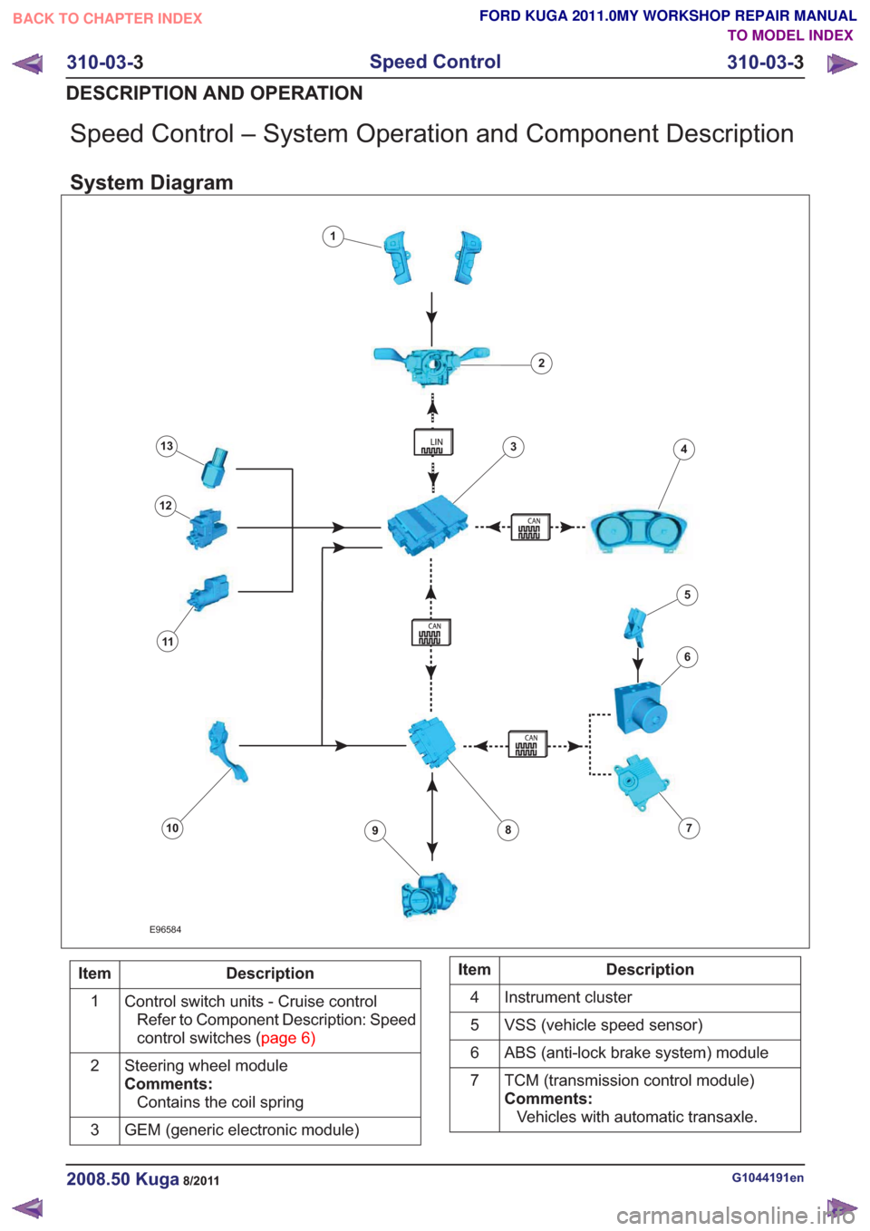
Speed Control – System Operation and Component Description
System Diagram
E96584
1
2
34
6
78910
11
12
13
5
Description
Item
Control switch units - Cruise controlRefer to Component Description: Speed
controlswitches(page6)
1
Steering wheel module
Comments:Contains the coil spring
2
GEM (generic electronic module)
3Description
Item
Instrument cluster
4
VSS (vehicle speed sensor)
5
ABS (anti-lock brake system) module
6
TCM (transmission control module)
Comments:Vehicles with automatic transaxle.
7
G1044191en2008.50 Kuga8/2011
310-03-
3
Speed Control
310-03- 3
DESCRIPTION AND OPERATION
TO MODEL INDEX
BACK TO CHAPTER INDEX
FORD KUGA 2011.0MY WORKSHOP REPAIR MANUAL