Engine FORD KUGA 2011 1.G Repair Manual
[x] Cancel search | Manufacturer: FORD, Model Year: 2011, Model line: KUGA, Model: FORD KUGA 2011 1.GPages: 2057
Page 1241 of 2057
7.
1
2x6
x3
1
2x6
x3
E101018
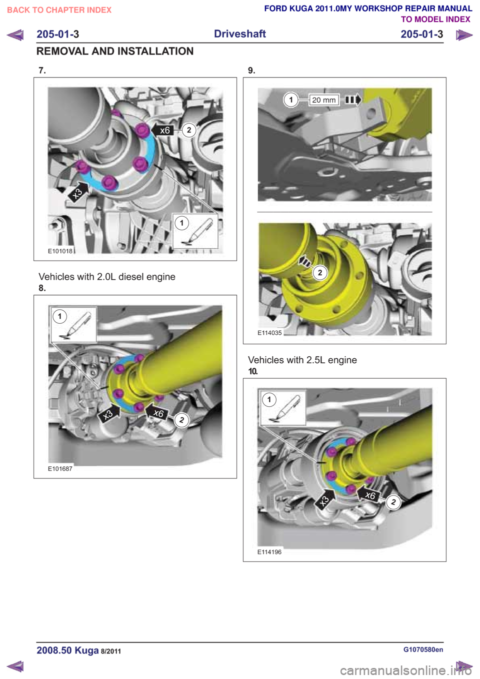
Vehicles with 2.0L diesel engine
8.
1
2x6x3
1
2x6x3
E101687
9.
20 mm1
2
20 mm1
2
E114035
Vehicles with 2.5L engine
10.
1
2x6
x3
1
2x6
x3
E114196
G1070580en2008.50 Kuga8/2011
205-01-3
Driveshaft
205-01- 3
REMOVAL AND INSTALLATION
TO MODEL INDEX
BACK TO CHAPTER INDEX
FORD KUGA 2011.0MY WORKSHOP REPAIR MANUAL
Page 1243 of 2057
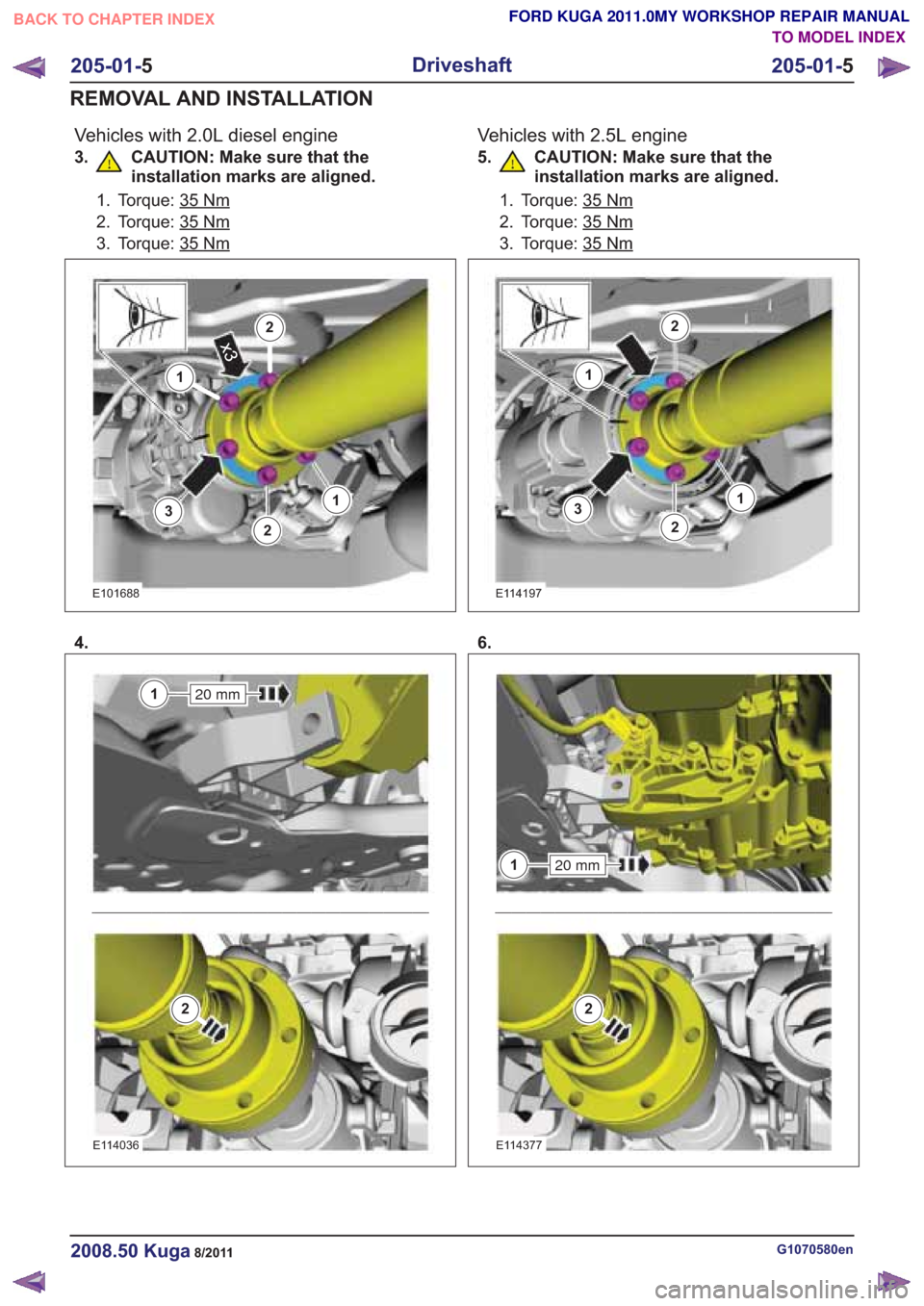
Vehicles with 2.0L diesel engine
3. CAUTION: Make sure that theinstallation marks are aligned.
1. Torque: 35Nm
2. Torque: 35Nm
3. Torque: 35Nm
3
1
2
2x3
13
1
2
2x3
1
E101688
4.
20 mm1
2
20 mm1
2
E114036
Vehicles with 2.5L engine
5. CAUTION: Make sure that theinstallation marks are aligned.
1. Torque: 35Nm
2. Torque: 35Nm
3. Torque: 35Nm
3
1
2
2
13
1
2
2
1
E114197
6.
20 mm1
2
20 mm1
2
E114377
G1070580en2008.50 Kuga8/2011
205-01- 5
Driveshaft
205-01- 5
REMOVAL AND INSTALLATION
TO MODEL INDEX
BACK TO CHAPTER INDEX
FORD KUGA 2011.0MY WORKSHOP REPAIR MANUAL
Page 1245 of 2057
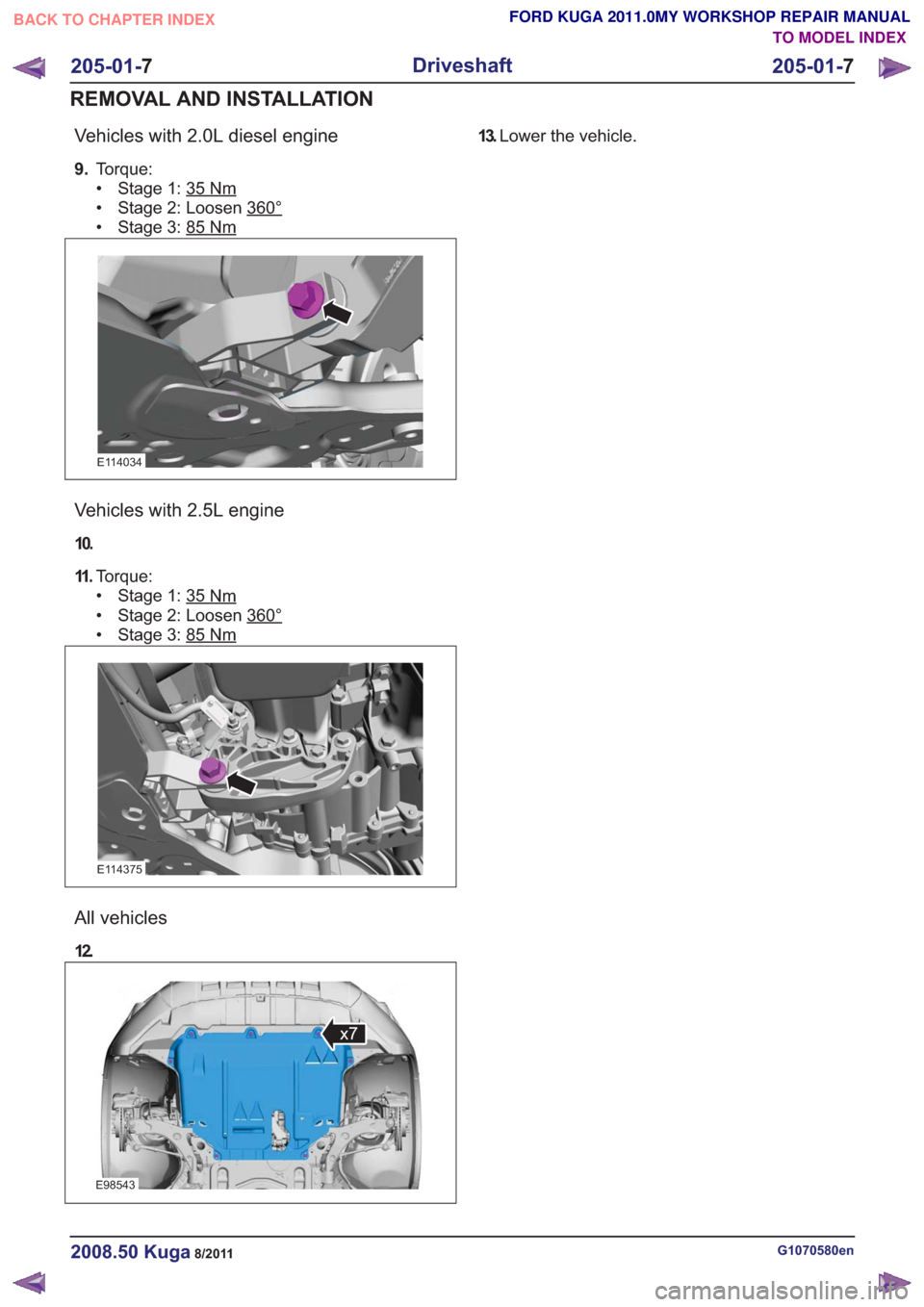
Vehicles with 2.0L diesel engine
9.Torque:
• Stage 1: 35
Nm
• Stage 2: Loosen 360°
• Stage 3: 85Nm
E114034
Vehicles with 2.5L engine
10.
11 .Torque:
• Stage 1: 35
Nm
• Stage 2: Loosen 360°
• Stage 3: 85Nm
E114375
All vehicles
12.
E98543
x7
13.Lower the vehicle.
G1070580en2008.50 Kuga8/2011
205-01- 7
Driveshaft
205-01- 7
REMOVAL AND INSTALLATION
TO MODEL INDEX
BACK TO CHAPTER INDEX
FORD KUGA 2011.0MY WORKSHOP REPAIR MANUAL
Page 1251 of 2057
Rear Drive Axle and Differential – System Operation andComponent Description
System Operation
General Information
The powertrain with all-wheel drive consists of the
following main components:
• engine
• transaxle with front axle differential
• transfer box
• halfshafts and driveshafts
• Haldex clutch
• rear axle differential
The Haldex clutch guarantees continuous variable
torque transmission to the rear axle under all
driving conditions. The Haldex clutch reacts
immediately and equally quickly with slow or fast
wheel slip.
A difference in angle of rotation of 90° between the
input and output shafts is required to build up
maximum pressure at the multi-plate clutch or to
transmit maximum torque.
The advantage of vehicles with all-wheel drive is
that they distribute the drive between all four
wheels. They therefore have a higher tractive
power. They feature improved cornering behaviour,
as the grip at all four wheels can be better utilised.
Thus, the wheels contribute to a greater degree
towards cornering stability.
The engine torque is transmitted from the transfer
box to the rear axle via a driveshaft. The driveshaft
is flange-mounted to the input side of the Haldex
clutch.
Driving situations
Pulling away and accelerating
• When pulling away and accelerating, as muchall-wheel drive as necessary must be available
immediately in the short-term. During
acceleration, the electronic system detects slip
at the front axle. This slip is counter-controlled
and thus the propulsive force optimally
distributed to the two axes.
Cornering • A sporty driving style, in particular dynamic
cornering, demands stable cornering behaviour.
The all-wheel system distributes the propulsive
force to all four wheels and by so doing boosts
the high cornering forces so that the vehicle
makes optimum contact with the road surface.
Snow and black ice
• Snow and black ice require particularly high grip. Under these conditions, the Haldex clutch
always distributes the propulsive force to the
axle with the better traction. The all-wheel
system reacts intelligently and quickly to all
driving situations.
Trailer operation
• When driving with a trailer, the trailer weight (support load) is transmitted to the rear axle via
the towbar. This reduces the load on the front
wheels, which means they can slip. The
electronic system detects this difference and
distributes most of the propulsive force to the
rear axle.
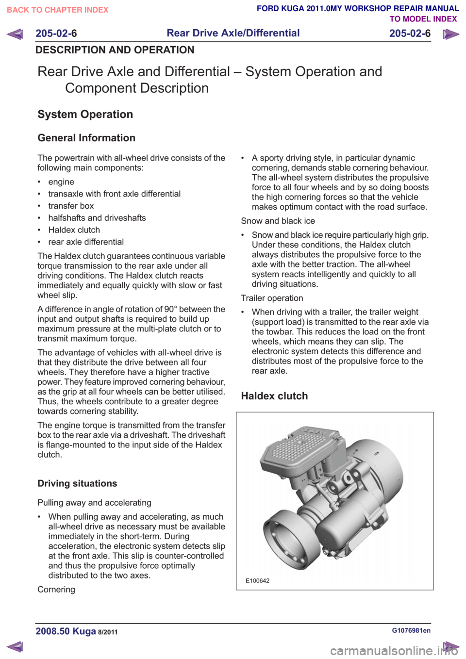
Haldex clutch
E100642
G1076981en2008.50 Kuga8/2011
205-02- 6
Rear Drive Axle/Differential
205-02- 6
DESCRIPTION AND OPERATION
TO MODEL INDEX
BACK TO CHAPTER INDEX
FORD KUGA 2011.0MY WORKSHOP REPAIR MANUAL
Page 1255 of 2057
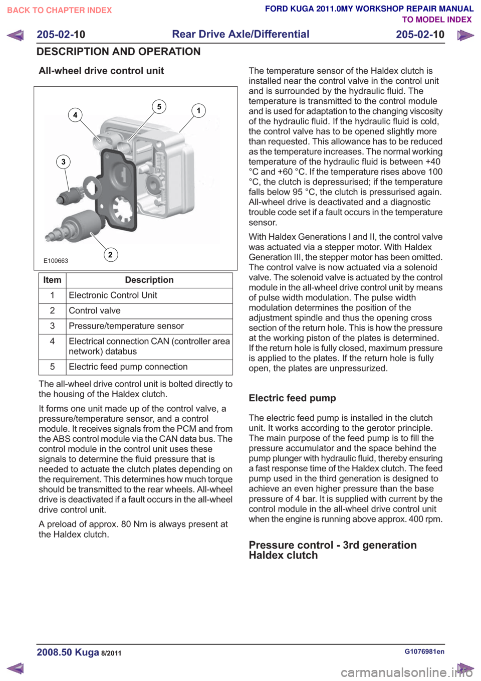
All-wheel drive control unit
E100663
14
3
2
5
Description
Item
Electronic Control Unit
1
Control valve
2
Pressure/temperature sensor
3
Electrical connection CAN (controller area
network) databus
4
Electric feed pump connection
5
The all-wheel drive control unit is bolted directly to
the housing of the Haldex clutch.
It forms one unit made up of the control valve, a
pressure/temperature sensor, and a control
module. It receives signals from the PCM and from
the ABS control module via the CAN data bus. The
control module in the control unit uses these
signals to determine the fluid pressure that is
needed to actuate the clutch plates depending on
the requirement. This determines how much torque
should be transmitted to the rear wheels. All-wheel
drive is deactivated if a fault occurs in the all-wheel
drive control unit.
A preload of approx. 80 Nm is always present at
the Haldex clutch. The temperature sensor of the Haldex clutch is
installed near the control valve in the control unit
and is surrounded by the hydraulic fluid. The
temperature is transmitted to the control module
and is used for adaptation to the changing viscosity
of the hydraulic fluid. If the hydraulic fluid is cold,
the control valve has to be opened slightly more
than requested. This allowance has to be reduced
as the temperature increases. The normal working
temperature of the hydraulic fluid is between +40
°C and +60 °C. If the temperature rises above 100
°C, the clutch is depressurised; if the temperature
falls below 95 °C, the clutch is pressurised again.
All-wheel drive is deactivated and a diagnostic
trouble code set if a fault occurs in the temperature
sensor.
With Haldex Generations I and II, the control valve
was actuated via a stepper motor. With Haldex
Generation III, the stepper motor has been omitted.
The control valve is now actuated via a solenoid
valve. The solenoid valve is actuated by the control
module in the all-wheel drive control unit by means
of pulse width modulation. The pulse width
modulation determines the position of the
adjustment spindle and thus the opening cross
section of the return hole. This is how the pressure
at the working piston of the plates is determined.
If the return hole is fully closed, maximum pressure
is applied to the plates. If the return hole is fully
open, the plates are unpressurized.
Electric feed pump
The electric feed pump is installed in the clutch
unit. It works according to the gerotor principle.
The main purpose of the feed pump is to fill the
pressure accumulator and the space behind the
pump plunger with hydraulic fluid, thereby ensuring
a fast response time of the Haldex clutch. The feed
pump used in the third generation is designed to
achieve an even higher pressure than the base
pressure of 4 bar. It is supplied with current by the
control module in the all-wheel drive control unit
when the engine is running above approx. 400 rpm.
Pressure control - 3rd generation
Haldex clutch
G1076981en2008.50 Kuga8/2011
205-02-
10
Rear Drive Axle/Differential
205-02- 10
DESCRIPTION AND OPERATION
TO MODEL INDEX
BACK TO CHAPTER INDEX
FORD KUGA 2011.0MY WORKSHOP REPAIR MANUAL
Page 1261 of 2057
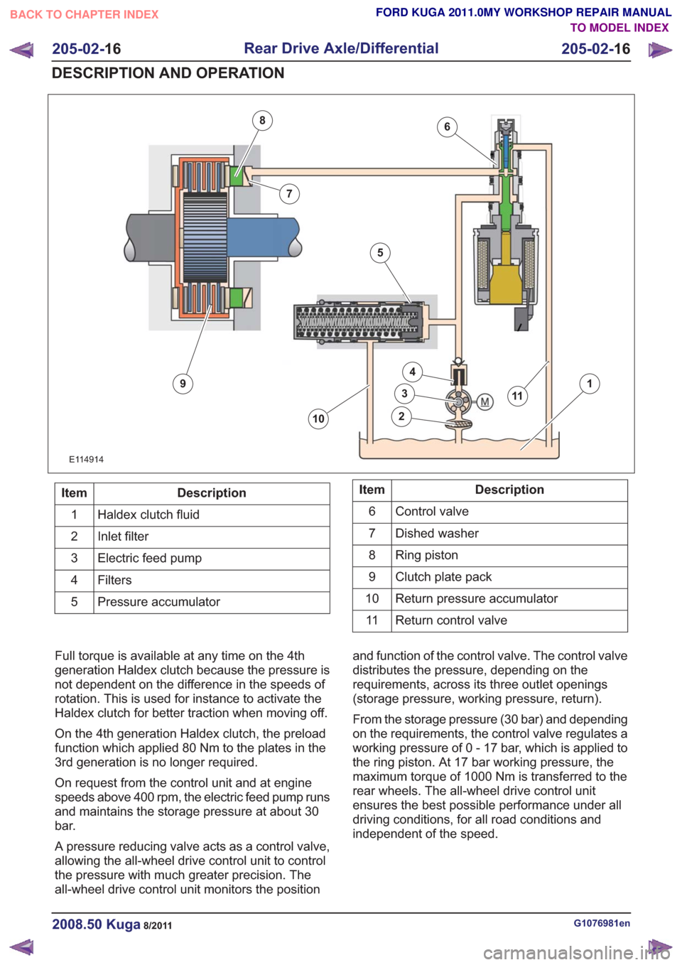
6
7
8
9
10
11
1
2
3
4
5
6
7
8
9
10
11
E114914
Description
Item
Haldex clutch fluid
1
Inlet filter
2
Electric feed pump
3
Filters4
Pressure accumulator
5Description
Item
Control valve
6
Dished washer
7
Ring piston
8
Clutch plate pack
9
Return pressure accumulator
10
Return control valve
11
Full torque is available at any time on the 4th
generation Haldex clutch because the pressure is
not dependent on the difference in the speeds of
rotation. This is used for instance to activate the
Haldex clutch for better traction when moving off.
On the 4th generation Haldex clutch, the preload
function which applied 80 Nm to the plates in the
3rd generation is no longer required.
On request from the control unit and at engine
speeds above 400 rpm, the electric feed pump runs
and maintains the storage pressure at about 30
bar.
A pressure reducing valve acts as a control valve,
allowing the all-wheel drive control unit to control
the pressure with much greater precision. The
all-wheel drive control unit monitors the position and function of the control valve. The control valve
distributes the pressure, depending on the
requirements, across its three outlet openings
(storage pressure, working pressure, return).
From the storage pressure (30 bar) and depending
on the requirements, the control valve regulates a
working pressure of 0 - 17 bar, which is applied to
the ring piston. At 17 bar working pressure, the
maximum torque of 1000 Nm is transferred to the
rear wheels. The all-wheel drive control unit
ensures the best possible performance under all
driving conditions, for all road conditions and
independent of the speed.
G1076981en2008.50 Kuga8/2011
205-02-
16
Rear Drive Axle/Differential
205-02- 16
DESCRIPTION AND OPERATION
TO MODEL INDEX
BACK TO CHAPTER INDEX
FORD KUGA 2011.0MY WORKSHOP REPAIR MANUAL
Page 1266 of 2057
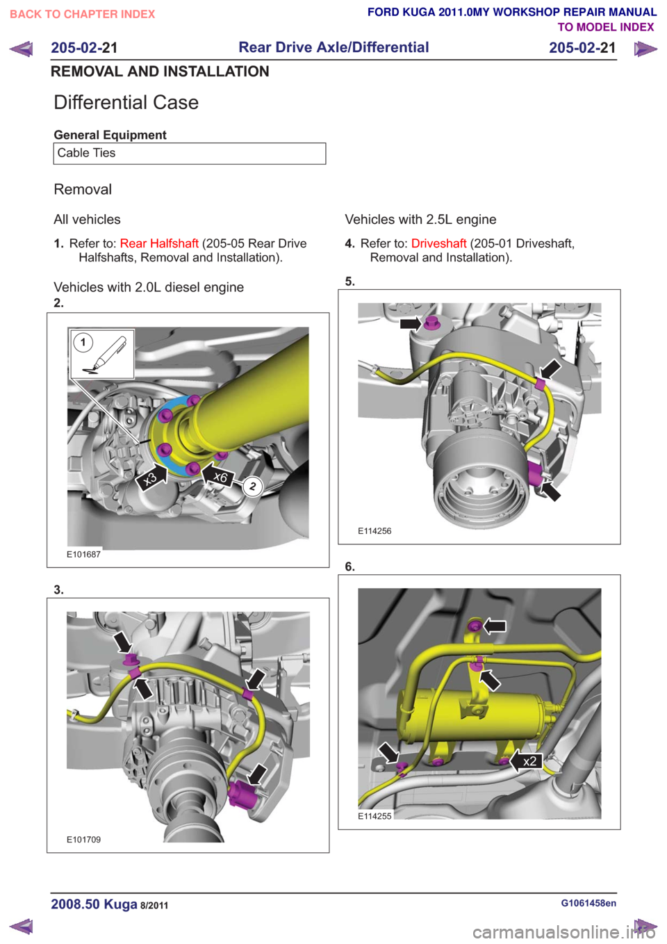
Differential Case
General EquipmentCable Ties
Removal
All vehicles
1. Refer to: Rear Halfshaft (205-05 Rear Drive
Halfshafts, Removal and Installation).
Vehicles with 2.0L diesel engine
2.
1
2x6x3
1
2x6x3
E101687
3.
E101709
Vehicles with 2.5L engine
4. Refer to: Driveshaft (205-01 Driveshaft,
Removal and Installation).
5.
E114256
6.
x2x2
E114255
G1061458en2008.50 Kuga8/2011
205-02- 21
Rear Drive Axle/Differential
205-02- 21
REMOVAL AND INSTALLATION
TO MODEL INDEX
BACK TO CHAPTER INDEX
FORD KUGA 2011.0MY WORKSHOP REPAIR MANUAL
Page 1267 of 2057
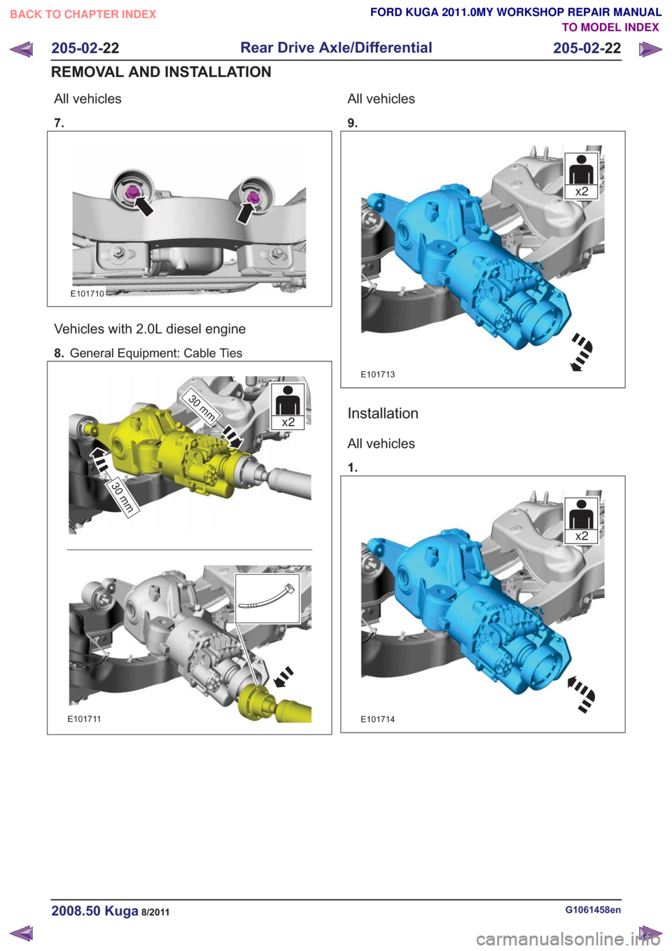
All vehicles
7.
E101710
Vehicles with 2.0L diesel engine
8.General Equipment: Cable Ties
30 mm
30 mm
x2
30 mm
30 mm
x2
E101711
All vehicles
9.
x2x2
E101713
Installation
All vehicles
1.
x2x2
E101714
G1061458en2008.50 Kuga8/2011
205-02- 22
Rear Drive Axle/Differential
205-02- 22
REMOVAL AND INSTALLATION
TO MODEL INDEX
BACK TO CHAPTER INDEX
FORD KUGA 2011.0MY WORKSHOP REPAIR MANUAL
Page 1268 of 2057
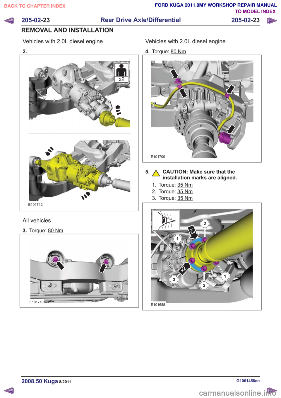
Vehicles with 2.0L diesel engine
2.
x2x2
E101712
All vehicles
3.Torque: 80Nm
E101710
Vehicles with 2.0L diesel engine
4.Torque: 80Nm
E101709
5. CAUTION: Make sure that the
installation marks are aligned.
1. Torque: 35Nm
2. Torque: 35Nm
3. Torque: 35Nm
3
x2
1
2
2x3
13
x2
1
2
2x3
1
E101688
G1061458en2008.50 Kuga8/2011
205-02- 23
Rear Drive Axle/Differential
205-02- 23
REMOVAL AND INSTALLATION
TO MODEL INDEX
BACK TO CHAPTER INDEX
FORD KUGA 2011.0MY WORKSHOP REPAIR MANUAL
Page 1269 of 2057
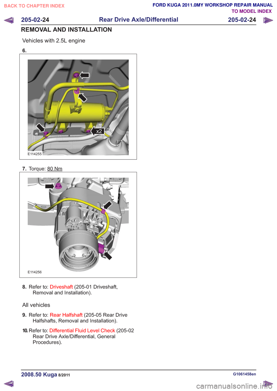
Vehicles with 2.5L engine
6.
x2x2
E114255
7.Torque: 80Nm
E114256
8.Refer to: Driveshaft (205-01 Driveshaft,
Removal and Installation).
All vehicles
9. Refer to: Rear Halfshaft (205-05 Rear Drive
Halfshafts, Removal and Installation).
10. Refer to: Differential Fluid Level Check (205-02
Rear Drive Axle/Differential, General
Procedures).
G1061458en2008.50 Kuga8/2011
205-02- 24
Rear Drive Axle/Differential
205-02- 24
REMOVAL AND INSTALLATION
TO MODEL INDEX
BACK TO CHAPTER INDEX
FORD KUGA 2011.0MY WORKSHOP REPAIR MANUAL