pump FORD KUGA 2011 1.G Repair Manual
[x] Cancel search | Manufacturer: FORD, Model Year: 2011, Model line: KUGA, Model: FORD KUGA 2011 1.GPages: 2057
Page 1674 of 2057
Engine Cooling — 2.5L Duratec (147kW/200PS) - VI5 – Overview
Auxiliary coolant pump
An electrically operated auxiliary coolant pump is
installed on vehicles with a trailer coupling and/or
additional heating. The auxiliary coolant pump
ensures that the coolant is circulated when the
coolant pump (which is driven by the engine) is not
running.
The additional heating uses the auxiliary coolant
pump to circulate hot coolant through the heat
exchanger and the engine.
On vehicles with a trailer coupling the auxiliary
coolant pump is switched on for 6 minutes by the
PCM (powertrain control module) if the coolant
temperature exceeds 106°C when the engine is
switched off. This prevents the coolant circuit from
overheating. This could happen particularly if the
engine is switched off after towing a heavy trailer
up a steep hill before there has been sufficient time
for cooling.
G1088220en2008.50 Kuga8/2011
303-03-3
Engine Cooling
303-03- 3
DESCRIPTION AND OPERATION
TO MODEL INDEX
BACK TO CHAPTER INDEX
FORD KUGA 2011.0MY WORKSHOP REPAIR MANUAL
Page 1675 of 2057
Engine Cooling
Special Tool(s) / General EquipmentPressure Tester, Cooling
System
303-396 (24-001 A)
IA24001A
Adaptor for 303-396
303-396-09
E55030
Ford approved diagnostic tool
Inspection and Verification
1. Verify the customer concern.
2. Visually inspect for obvious signs of mechanicalor electrical damage.
Visual Inspection Chart
Electrical
Mechanical
– Fuse(s)
– Wiring harness
– Electricalconnector(s)
– Engine coolant temperature (ECT)
sensor
– Cooling fan motor
– Cooling fan module
– Powertrain control module (PCM)
– Coolant shut off valve
– Coolant degas shut off valve
– Coolant leaks
– Gaskets/seals
– Core plug(s)
– Hose(s)/hose joints
– Coolant expansion
tank cap and seal(s)
– Coolant expansion tank
– Radiator
– Coolant pump
– Thermostat
– Heater core
– Exhaust gas recircu- lation (EGR) cooler
3. If an obvious cause for an observed or reported concern is found, correct the cause (if possible)
before proceeding to the next step.
4. If the cause is not visually evident, verify the symptom and refer to the diagnostic tab within
the Ford approved diagnostic tool.
G1058974en2008.50 Kuga8/2011
303-03- 4
Engine Cooling
303-03- 4
DIAGNOSIS AND TESTING
TO MODEL INDEX
BACK TO CHAPTER INDEX
FORD KUGA 2011.0MY WORKSHOP REPAIR MANUAL
Page 1681 of 2057
Coolant Pump — 2.5L Duratec (147kW/200PS) - VI5(24 404 0)
General EquipmentTrolley Jack
Removal
NOTE: Removal steps in this procedure may
contain installation details.
1. Drain the cooling system.
Refer to: Cooling System Draining and Vacuum
Filling (303-03 Engine Cooling, General
Procedures).
2. Remove the timing belt.
Refer to: Timing Belt (303-01 Engine - 2.5L
Duratec (147kW/200PS) - VI5, Removal and
Installation).
3. CAUTION: Use a wooden block to protect the oil pan when supporting the
engine.
Position the trolley jack with the wooden block
under the oil pan. Raise the trolley jack until the
front of the engine is free from load and the
coolant pump bolts can be accessed.
General Equipment: Trolley Jack
4. Torque: 17
Nm
E63823
x4
5.Lower the engine.
General Equipment: Trolley Jack 6.
Torque: 17
Nm
x3
E63856
Installation
1. NOTE: Install all the bolts finger tight before
final tightening.
To install, reverse the removal procedure.
G544632en2008.50 Kuga8/2011
303-03- 10
Engine Cooling
303-03- 10
REMOVAL AND INSTALLATION
TO MODEL INDEX
BACK TO CHAPTER INDEX
FORD KUGA 2011.0MY WORKSHOP REPAIR MANUAL
Page 1696 of 2057
Action
Possible Sources
Symptom
• INSPECT the fuel lines.INSTALL new components as
necessary. TEST the system
for normal operation.
• Fuel lines damaged or blocked.
• INSTALL a new fuel filter.
• Fuel filter blocked.
• REFER to:Fuel Pump and
Sender Unit - 2.5L Duratec
(147kW/200PS) - VI5 (310-01
Fuel Tank and Lines,
Removal and Installation).
• Fuel pump and sender unit.
• Carry out a full enginediagnosis using the guided
diagnostic menu in the Ford
diagnostic equipment.
• Crankshaft position (CKP)
sensor.
• Carry out a full enginediagnosis using the guided
diagnostic menu in the Ford
diagnostic equipment.
• Camshaft position (CMP)
sensor.
• Carry out a full enginediagnosis using the guided
diagnostic menu in the Ford
diagnostic equipment.
•PCM.
• Carry out a full enginediagnosis using the guided
diagnostic menu in the Ford
diagnostic equipment.
• Fuel rail fuel pressure sensor.
• INSPECT the fuel injectors.CLEAN the fuel injectors or
INSTALL a new set of injectors
as required only after the
checks have been carried out.
REFER to: Fuel Injectors (303-
04 Fuel Charging and
Controls - 2.5L Duratec
(147kW/200PS) - VI5,
Removal and Installation).
• Fuel injectors.
• CHECK the valve timing.REFER to: Timing Belt (303-01
Engine - 2.5L Duratec
(147kW/200PS) - VI5,
Removal and Installation).
• Incorrect valve timing.
• TEST the cylinder compres-sion.
REFER to: Engine(303-00
Engine System - General
Information, Diagnosis and
Testing).
• Low cylinder compression.
G1183441en2008.50 Kuga8/2011
303-04A-
5
Fuel Charging and Controls
— 2.5L Duratec (147kW/200PS) -
VI5
303-04A- 5
DIAGNOSIS AND TESTING
TO MODEL INDEX
BACK TO CHAPTER INDEX
FORD KUGA 2011.0MY WORKSHOP REPAIR MANUAL
Page 1710 of 2057
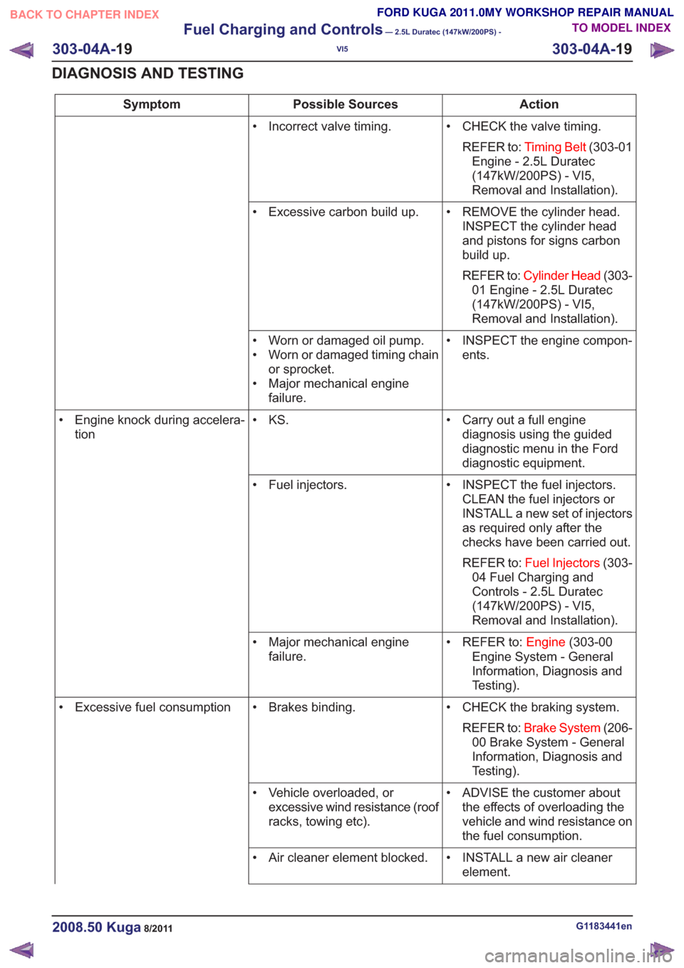
Action
Possible Sources
Symptom
• CHECK the valve timing.REFER to: Timing Belt (303-01
Engine - 2.5L Duratec
(147kW/200PS) - VI5,
Removal and Installation).
• Incorrect valve timing.
• REMOVE the cylinder head.INSPECT the cylinder head
and pistons for signs carbon
build up.
REFER to: Cylinder Head (303-
01 Engine - 2.5L Duratec
(147kW/200PS) - VI5,
Removal and Installation).
• Excessive carbon build up.
• INSPECT the engine compon-ents.
• Worn or damaged oil pump.
• Worn or damaged timing chain
or sprocket.
• Major mechanical engine failure.
• Carry out a full enginediagnosis using the guided
diagnostic menu in the Ford
diagnostic equipment.
• KS.
• Engine knock during accelera-
tion
• INSPECT the fuel injectors.CLEAN the fuel injectors or
INSTALL a new set of injectors
as required only after the
checks have been carried out.
REFER to: Fuel Injectors (303-
04 Fuel Charging and
Controls - 2.5L Duratec
(147kW/200PS) - VI5,
Removal and Installation).
• Fuel injectors.
• REFER to:Engine(303-00
Engine System - General
Information, Diagnosis and
Testing).
• Major mechanical engine
failure.
• CHECK the braking system.REFER to: Brake System (206-
00 Brake System - General
Information, Diagnosis and
Testing).
• Brakes binding.
• Excessive fuel consumption
• ADVISE the customer aboutthe effects of overloading the
vehicle and wind resistance on
the fuel consumption.
• Vehicle overloaded, or
excessive wind resistance (roof
racks, towing etc).
• INSTALL a new air cleanerelement.
• Air cleaner element blocked.
G1183441en2008.50 Kuga8/2011
303-04A-
19
Fuel Charging and Controls
— 2.5L Duratec (147kW/200PS) -
VI5
303-04A- 19
DIAGNOSIS AND TESTING
TO MODEL INDEX
BACK TO CHAPTER INDEX
FORD KUGA 2011.0MY WORKSHOP REPAIR MANUAL
Page 1725 of 2057
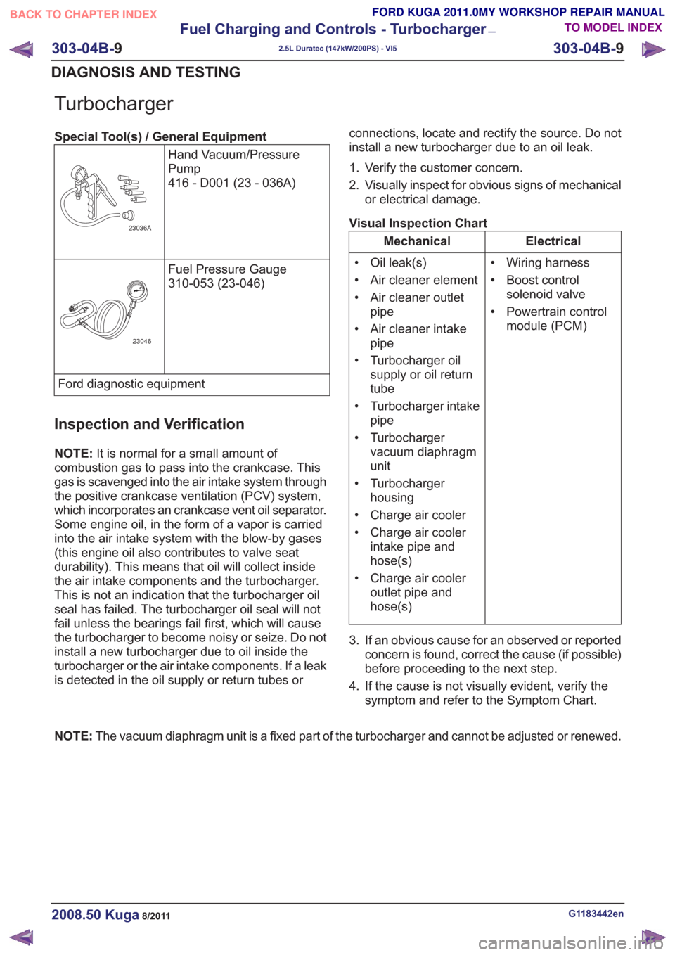
Turbocharger
Special Tool(s) / General EquipmentHand Vacuum/Pressure
Pump
416 - D001 (23 - 036A)
23036A
Fuel Pressure Gauge
310-053 (23-046)
23046
Ford diagnostic equipment
Inspection and Verification
NOTE:It is normal for a small amount of
combustion gas to pass into the crankcase. This
gas is scavenged into the air intake system through
the positive crankcase ventilation (PCV) system,
which incorporates an crankcase vent oil separator.
Some engine oil, in the form of a vapor is carried
into the air intake system with the blow-by gases
(this engine oil also contributes to valve seat
durability). This means that oil will collect inside
the air intake components and the turbocharger.
This is not an indication that the turbocharger oil
seal has failed. The turbocharger oil seal will not
fail unless the bearings fail first, which will cause
the turbocharger to become noisy or seize. Do not
install a new turbocharger due to oil inside the
turbocharger or the air intake components. If a leak
is detected in the oil supply or return tubes or connections, locate and rectify the source. Do not
install a new turbocharger due to an oil leak.
1. Verify the customer concern.
2. Visually inspect for obvious signs of mechanical
or electrical damage.
Visual Inspection Chart
Electrical
Mechanical
• Wiring harness
• Boost controlsolenoid valve
• Powertrain control module (PCM)
• Oil leak(s)
• Air cleaner element
• Air cleaner outlet
pipe
• Air cleaner intake pipe
• Turbocharger oil supply or oil return
tube
• Turbocharger intake pipe
• Turbocharger vacuum diaphragm
unit
• Turbocharger housing
• Charge air cooler
• Charge air cooler intake pipe and
hose(s)
• Charge air cooler outlet pipe and
hose(s)
3. If an obvious cause for an observed or reported concern is found, correct the cause (if possible)
before proceeding to the next step.
4. If the cause is not visually evident, verify the symptom and refer to the Symptom Chart.
NOTE: The vacuum diaphragm unit is a fixed part of the turbocharger and cannot be adjusted or renewed.
G1183442en2008.50 Kuga8/2011
303-04B- 9
Fuel Charging and Controls - Turbocharger
—
2.5L Duratec (147kW/200PS) - VI5
303-04B- 9
DIAGNOSIS AND TESTING
TO MODEL INDEX
BACK TO CHAPTER INDEX
FORD KUGA 2011.0MY WORKSHOP REPAIR MANUAL
Page 1780 of 2057
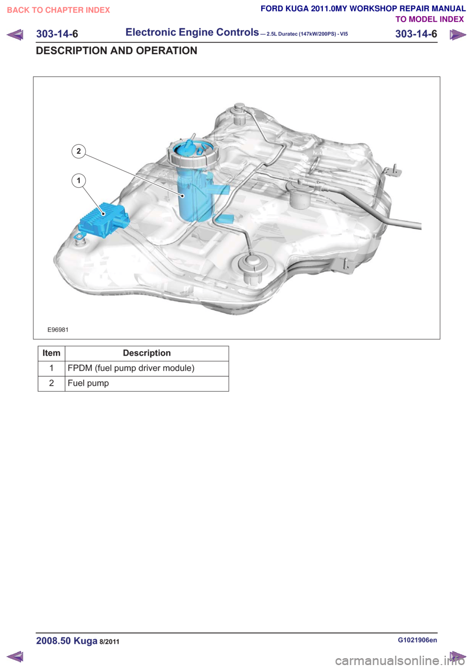
E96981
1
2
Description
Item
FPDM (fuel pump driver module)
1
Fuel pump
2
G1021906en2008.50 Kuga8/2011
303-14- 6
Electronic Engine Controls— 2.5L Duratec (147kW/200PS) - VI5303-14-
6
DESCRIPTION AND OPERATION
TO MODEL INDEX
BACK TO CHAPTER INDEX
FORD KUGA 2011.0MY WORKSHOP REPAIR MANUAL
Page 1790 of 2057
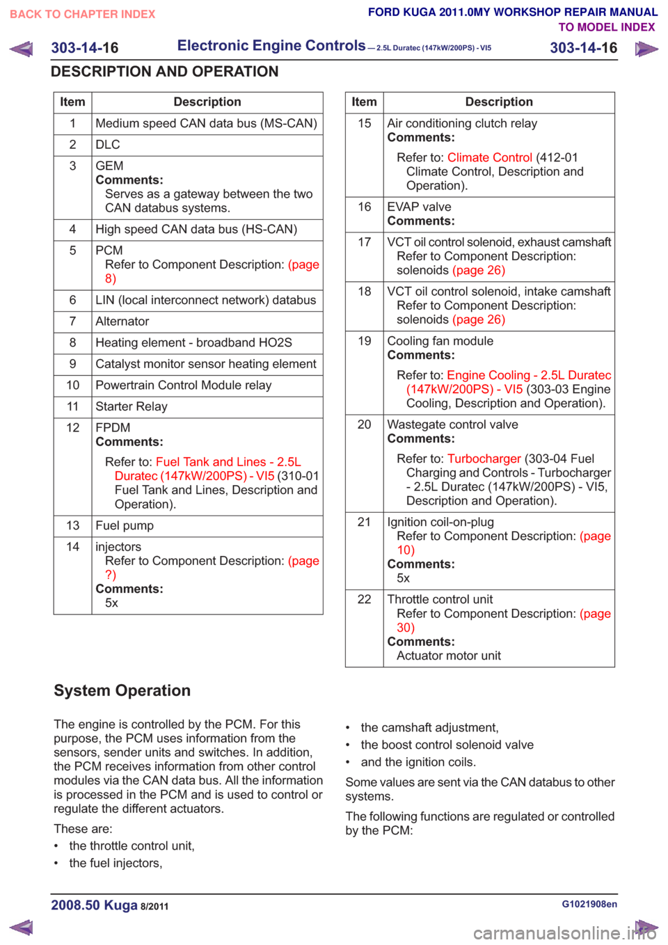
Description
Item
Medium speed CAN data bus (MS-CAN)
1
DLC
2
GEM
Comments:Serves as a gateway between the two
CAN databus systems.
3
High speed CAN data bus (HS-CAN)
4
PCMRefertoComponentDescription:(page
8)
5
LIN (local interconnect network) databus
6
Alternator
7
Heating element - broadband HO2S
8
Catalyst monitor sensor heating element
9
Powertrain Control Module relay
10
Starter Relay
11
FPDM
Comments:Refer to: Fuel Tank and Lines - 2.5L
Duratec (147kW/200PS) - VI5 (310-01
Fuel Tank and Lines, Description and
Operation).
12
Fuel pump
13
injectorsRefertoComponentDescription:(page
?)
Comments: 5x
14Description
Item
Air conditioning clutch relay
Comments:Refer to: Climate Control (412-01
Climate Control, Description and
Operation).
15
EVAP valve
Comments:
16
VCT oil control solenoid, exhaust camshaftRefer to Component Description:
solenoids(page26)
17
VCT oil control solenoid, intake camshaftRefer to Component Description:
solenoids(page26)
18
Cooling fan module
Comments:Refer to: Engine Cooling - 2.5L Duratec
(147kW/200PS) - VI5 (303-03 Engine
Cooling, Description and Operation).
19
Wastegate control valve
Comments:Refer to: Turbocharger (303-04 Fuel
Charging and Controls - Turbocharger
- 2.5L Duratec (147kW/200PS) - VI5,
Description and Operation).
20
Ignition coil-on-plugRefertoComponentDescription:(page
10)
Comments: 5x
21
Throttle control unitRefertoComponentDescription:(page
30)
Comments: Actuator motor unit
22
System Operation
The engine is controlled by the PCM. For this
purpose, the PCM uses information from the
sensors, sender units and switches. In addition,
the PCM receives information from other control
modules via the CAN data bus. All the information
is processed in the PCM and is used to control or
regulate the different actuators.
These are:
• the throttle control unit,
• the fuel injectors, • the camshaft adjustment,
• the boost control solenoid valve
• and the ignition coils.
Some values are sent via the CAN databus to other
systems.
The following functions are regulated or controlled
by the PCM:
G1021908en2008.50 Kuga8/2011
303-14-
16
Electronic Engine Controls— 2.5L Duratec (147kW/200PS) - VI5303-14-
16
DESCRIPTION AND OPERATION
TO MODEL INDEX
BACK TO CHAPTER INDEX
FORD KUGA 2011.0MY WORKSHOP REPAIR MANUAL
Page 1792 of 2057
• Torque reduction request (stability assistmodule)
• Cruise control request
The PCM sends the following signals via the CAN
databus:
• Fuel pump relay on/off
• Engine speed
• Warning lights on/off (MIL (malfunction indicator lamp), battery warning lamp)
• PAT S
•ECT
• Air conditioning pressure transducer
• Outside air temperature
With the aid of the input and output signals listed
above, the PCM controls / regulates engine
starting, fuel injection and fuel pressure, ignition,
boost pressure, camshaft adjustment, tank purging,
the radiator fan and the refrigerant compressor.
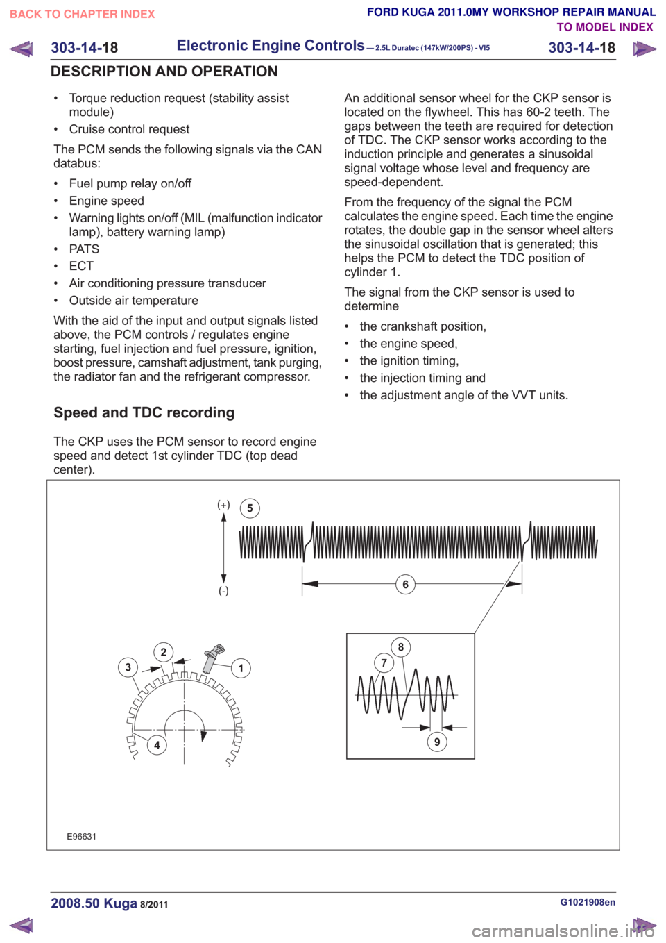
Speed and TDC recording
The CKP uses the PCM sensor to record engine
speed and detect 1st cylinder TDC (top dead
center). An additional sensor wheel for the CKP sensor is
located on the flywheel. This has 60-2 teeth. The
gaps between the teeth are required for detection
of TDC. The CKP sensor works according to the
induction principle and generates a sinusoidal
signal voltage whose level and frequency are
speed-dependent.
From the frequency of the signal the PCM
calculates the engine speed. Each time the engine
rotates, the double gap in the sensor wheel alters
the sinusoidal oscillation that is generated; this
helps the PCM to detect the TDC position of
cylinder 1.
The signal from the CKP sensor is used to
determine
• the crankshaft position,
• the engine speed,
• the ignition timing,
• the injection timing and
• the adjustment angle of the VVT units.
2
3
4
1
9
7
8
6
5
2
3
4
1
9
7
8
6
5
E96631
G1021908en2008.50 Kuga8/2011
303-14-
18
Electronic Engine Controls— 2.5L Duratec (147kW/200PS) - VI5303-14-
18
DESCRIPTION AND OPERATION
TO MODEL INDEX
BACK TO CHAPTER INDEX
FORD KUGA 2011.0MY WORKSHOP REPAIR MANUAL
Page 1794 of 2057
than to a change in the throttle valve position. The
ignition timing also changes much more quickly.
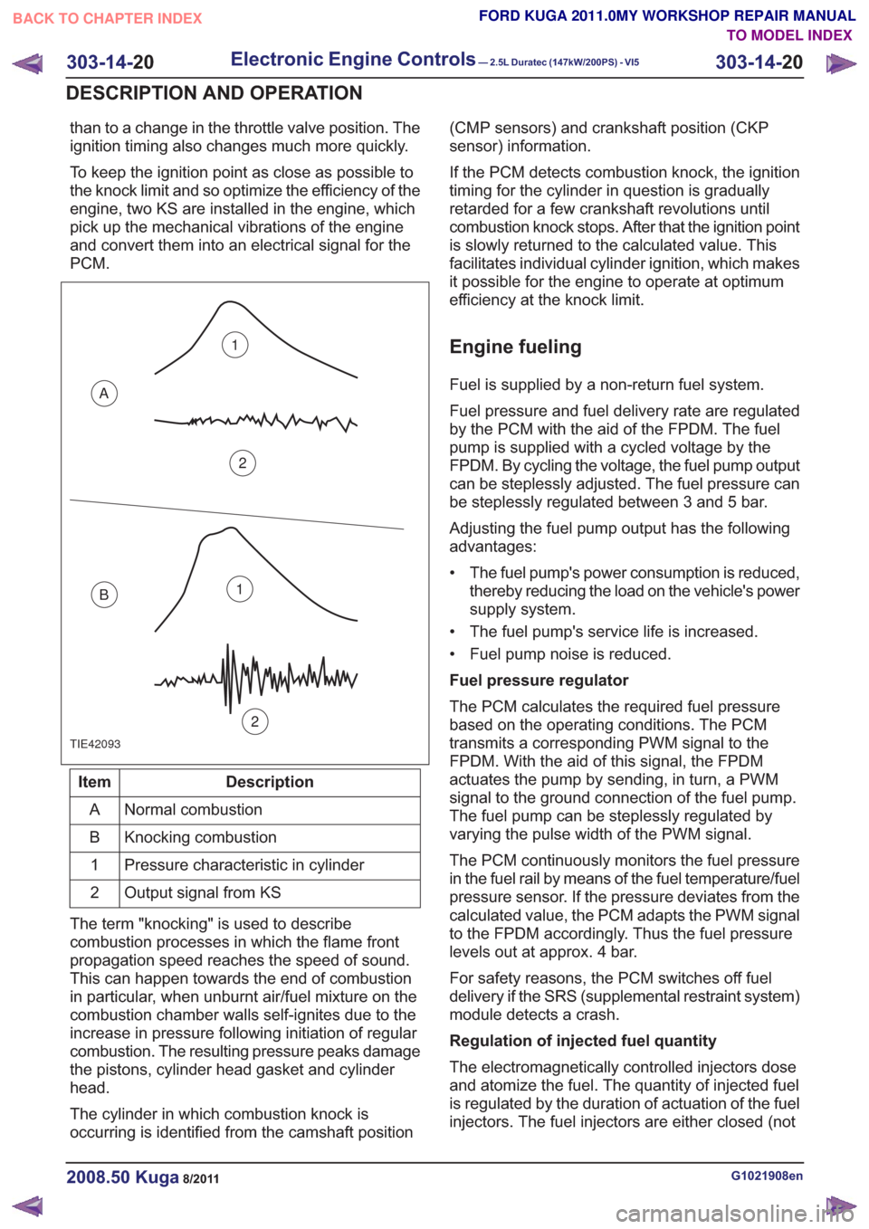
To keep the ignition point as close as possible to
the knock limit and so optimize the efficiency of the
engine, two KS are installed in the engine, which
pick up the mechanical vibrations of the engine
and convert them into an electrical signal for the
PCM.
TIE42093
1
2
A
B1
2
Description
Item
Normal combustion
A
Knocking combustion
B
Pressure characteristic in cylinder
1
Output signal from KS
2
The term "knocking" is used to describe
combustion processes in which the flame front
propagation speed reaches the speed of sound.
This can happen towards the end of combustion
in particular, when unburnt air/fuel mixture on the
combustion chamber walls self-ignites due to the
increase in pressure following initiation of regular
combustion. The resulting pressure peaks damage
the pistons, cylinder head gasket and cylinder
head.
The cylinder in which combustion knock is
occurring is identified from the camshaft position (CMP sensors) and crankshaft position (CKP
sensor) information.
If the PCM detects combustion knock, the ignition
timing for the cylinder in question is gradually
retarded for a few crankshaft revolutions until
combustion knock stops. After that the ignition point
is slowly returned to the calculated value. This
facilitates individual cylinder ignition, which makes
it possible for the engine to operate at optimum
efficiency at the knock limit.
Engine fueling
Fuel is supplied by a non-return fuel system.
Fuel pressure and fuel delivery rate are regulated
by the PCM with the aid of the FPDM. The fuel
pump is supplied with a cycled voltage by the
FPDM. By cycling the voltage, the fuel pump output
can be steplessly adjusted. The fuel pressure can
be steplessly regulated between 3 and 5 bar.
Adjusting the fuel pump output has the following
advantages:
• The fuel pump's power consumption is reduced,
thereby reducing the load on the vehicle's power
supply system.
• The fuel pump's service life is increased.
• Fuel pump noise is reduced.
Fuel pressure regulator
The PCM calculates the required fuel pressure
based on the operating conditions. The PCM
transmits a corresponding PWM signal to the
FPDM. With the aid of this signal, the FPDM
actuates the pump by sending, in turn, a PWM
signal to the ground connection of the fuel pump.
The fuel pump can be steplessly regulated by
varying the pulse width of the PWM signal.
The PCM continuously monitors the fuel pressure
in the fuel rail by means of the fuel temperature/fuel
pressure sensor. If the pressure deviates from the
calculated value, the PCM adapts the PWM signal
to the FPDM accordingly. Thus the fuel pressure
levels out at approx. 4 bar.
For safety reasons, the PCM switches off fuel
delivery if the SRS (supplemental restraint system)
module detects a crash.
Regulation of injected fuel quantity
The electromagnetically controlled injectors dose
and atomize the fuel. The quantity of injected fuel
is regulated by the duration of actuation of the fuel
injectors. The fuel injectors are either closed (not
G1021908en2008.50 Kuga8/2011
303-14- 20
Electronic Engine Controls— 2.5L Duratec (147kW/200PS) - VI5303-14-
20
DESCRIPTION AND OPERATION
TO MODEL INDEX
BACK TO CHAPTER INDEX
FORD KUGA 2011.0MY WORKSHOP REPAIR MANUAL