Body control module FORD KUGA 2011 1.G Workshop Manual
[x] Cancel search | Manufacturer: FORD, Model Year: 2011, Model line: KUGA, Model: FORD KUGA 2011 1.GPages: 2057
Page 183 of 2057
Instrument Cluster and Panel Illumination
Refer to
Wiring Diagrams Section 413-00, for
schematic and connector information.
Principles of Operation
NOTE: A new instrument cluster must be
configured.
The instrument cluster and panel illumination
consists of dimmable and non-dimmable
illumination. The dimmable panel illumination is
controlled by the panel illumination switch (part of
the headlamp switch), which allows the brightness
level of the backlights to be adjusted dependent
on the customer preference. When the headlamp
switch is in the parking lamps ON or headlamps
ON position, the intensity of the backlighting can
be adjusted using the panel dimmer switch. The
non dimmable illumination allows for full intensity
dependant on the ignition switch position.
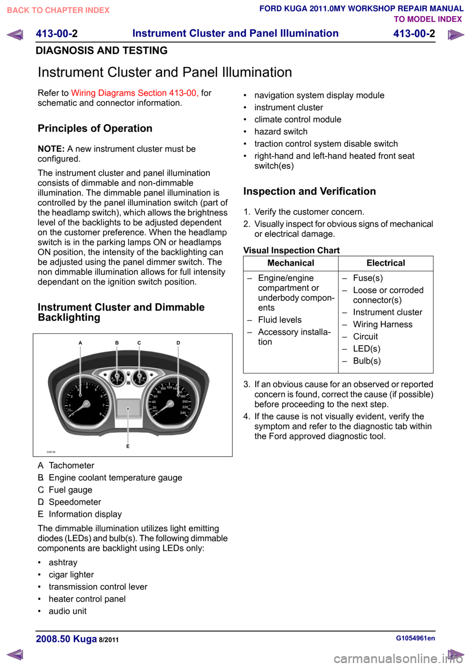
Instrument Cluster and Dimmable
Backlighting A.
Tachometer
B. Engine coolant temperature gauge
C. Fuel gauge
D. Speedometer
E. Information display
The dimmable illumination utilizes light emitting
diodes (LEDs) and bulb(s). The following dimmable
components are backlight using LEDs only:
• ashtray
• cigar lighter
• transmission control lever
• heater control panel
• audio unit • navigation system display module
• instrument cluster
• climate control module
• hazard switch
• traction control system disable switch
• right-hand and left-hand heated front seat
switch(es)
Inspection and Verification
1. Verify the customer concern.
2. Visually inspect for obvious signs of mechanical
or electrical damage.
Visual Inspection Chart Electrical
Mechanical
– Fuse(s)
– Loose or corrodedconnector(s)
– Instrument cluster
– Wiring Harness
– Circuit
– LED(s)
– Bulb(s)
– Engine/engine
compartment or
underbody compon-
ents
– Fluid levels
– Accessory installa- tion
3. If an obvious cause for an observed or reported concern is found, correct the cause (if possible)
before proceeding to the next step.
4. If the cause is not visually evident, verify the symptom and refer to the diagnostic tab within
the Ford approved diagnostic tool. G1054961en
2008.50 Kuga 8/2011 413-00-2
Instrument Cluster and Panel Illumination
413-00-2
DIAGNOSIS AND TESTINGTO MODEL INDEX
BACK TO CHAPTER INDEX
FORD KUGA 2011.0MY WORKSHOP REPAIR MANUALE98738ABCED
Page 1767 of 2057
E105848
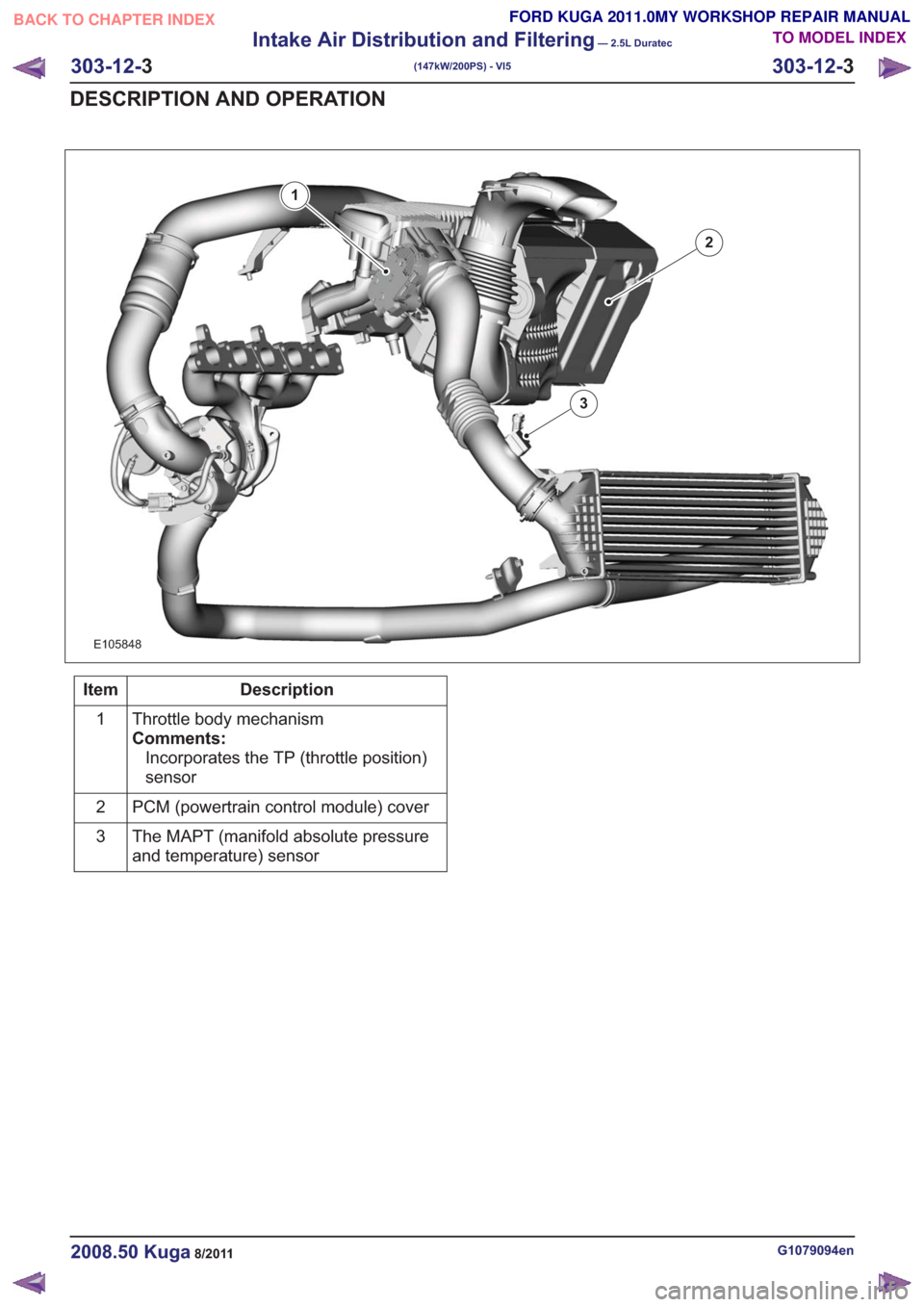
1
2
3
Description
Item
Throttle body mechanism
Comments:Incorporates the TP (throttle position)
sensor
1
PCM (powertrain control module) cover
2
The MAPT (manifold absolute pressure
and temperature) sensor
3
G1079094en2008.50 Kuga8/2011
303-12-
3
Intake Air Distribution and Filtering
— 2.5L Duratec
(147kW/200PS) - VI5
303-12- 3
DESCRIPTION AND OPERATION
TO MODEL INDEX
BACK TO CHAPTER INDEX
FORD KUGA 2011.0MY WORKSHOP REPAIR MANUAL
Page 1817 of 2057
Powertrain Control Module (PCM)(29 200 0)
General Equipment3.5 mm Drill Bit
Center Punch
Ford Diagnostic Equipment
Removal
NOTE: Removal steps in this procedure may
contain installation details.
1. NOTE: This step is only necessary when
installing a new component.
Download the PCM and throttle body
configuration information into the diagnostic tool,
using the Programmable Modules Installation
routine.
General Equipment: Ford Diagnostic Equipment
2. Refer to: Battery Disconnect and Connect
(414-01 Battery, Mounting and Cables,
General Procedures).
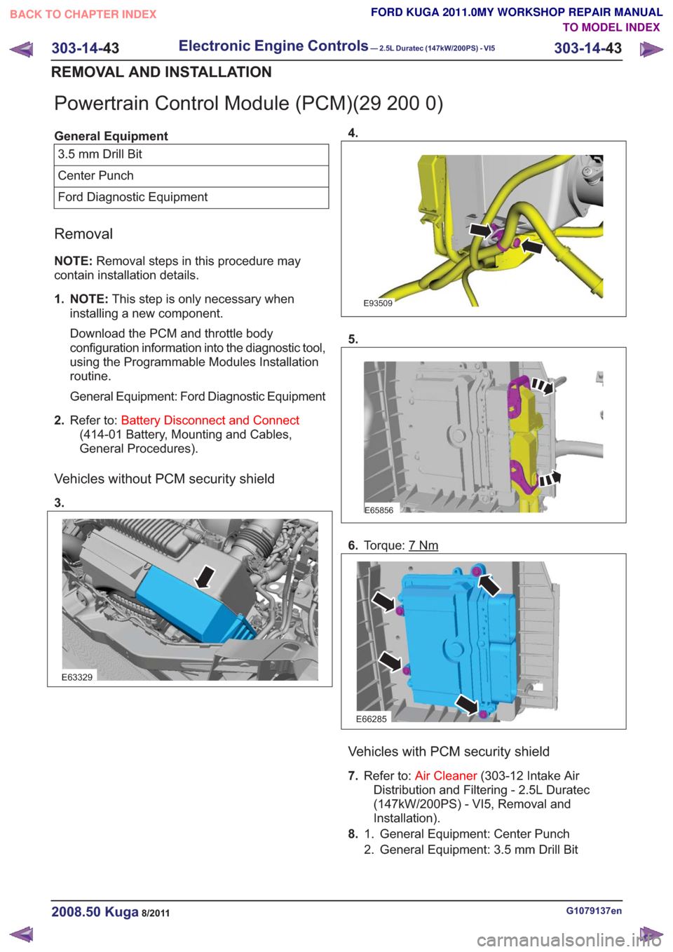
Vehicles without PCM security shield
3.
E63329
4.
E93509
5.
E65856
6. Torque: 7Nm
E66285
Vehicles with PCM security shield
7.Refer to: Air Cleaner (303-12 Intake Air
Distribution and Filtering - 2.5L Duratec
(147kW/200PS) - VI5, Removal and
Installation).
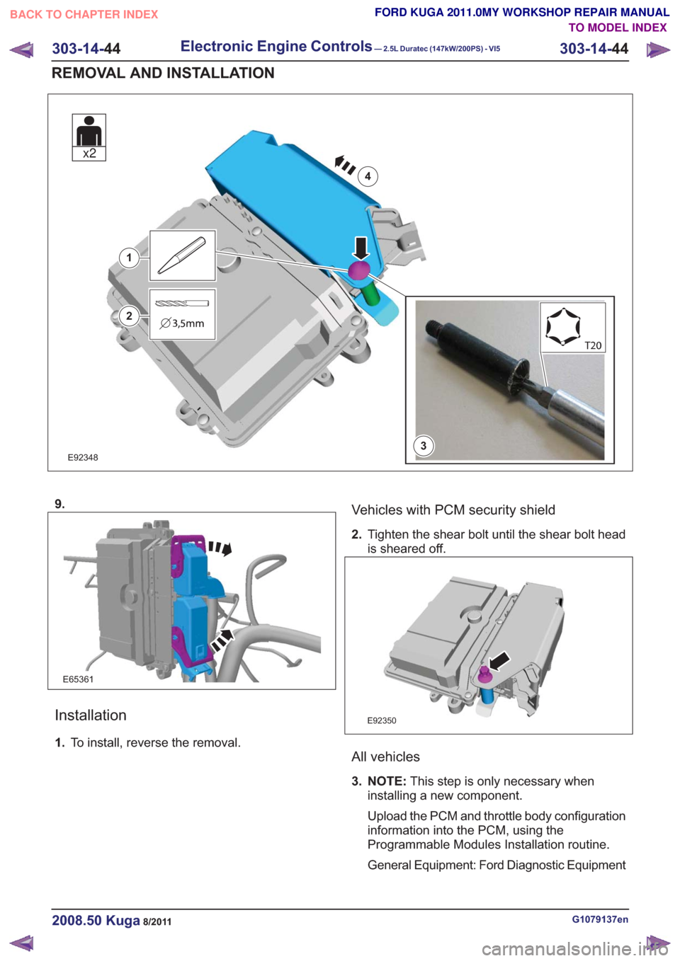
8. General Equipment: Center Punch
1.
2. General Equipment: 3.5 mm Drill Bit
G1079137en2008.50 Kuga8/2011
303-14- 43
Electronic Engine Controls— 2.5L Duratec (147kW/200PS) - VI5303-14-
43
REMOVAL AND INSTALLATION
TO MODEL INDEX
BACK TO CHAPTER INDEX
FORD KUGA 2011.0MY WORKSHOP REPAIR MANUAL
Page 1818 of 2057
E923483
1
2
4
x2
9.
E65361
Installation
1.To install, reverse the removal.
Vehicles with PCM security shield
2.Tighten the shear bolt until the shear bolt head
is sheared off.
E92350
All vehicles
3. NOTE: This step is only necessary when
installing a new component.
Upload the PCM and throttle body configuration
information into the PCM, using the
Programmable Modules Installation routine.
General Equipment: Ford Diagnostic Equipment
G1079137en2008.50 Kuga8/2011
303-14- 44
Electronic Engine Controls— 2.5L Duratec (147kW/200PS) - VI5303-14-
44
REMOVAL AND INSTALLATION
TO MODEL INDEX
BACK TO CHAPTER INDEX
FORD KUGA 2011.0MY WORKSHOP REPAIR MANUAL
Page 1823 of 2057
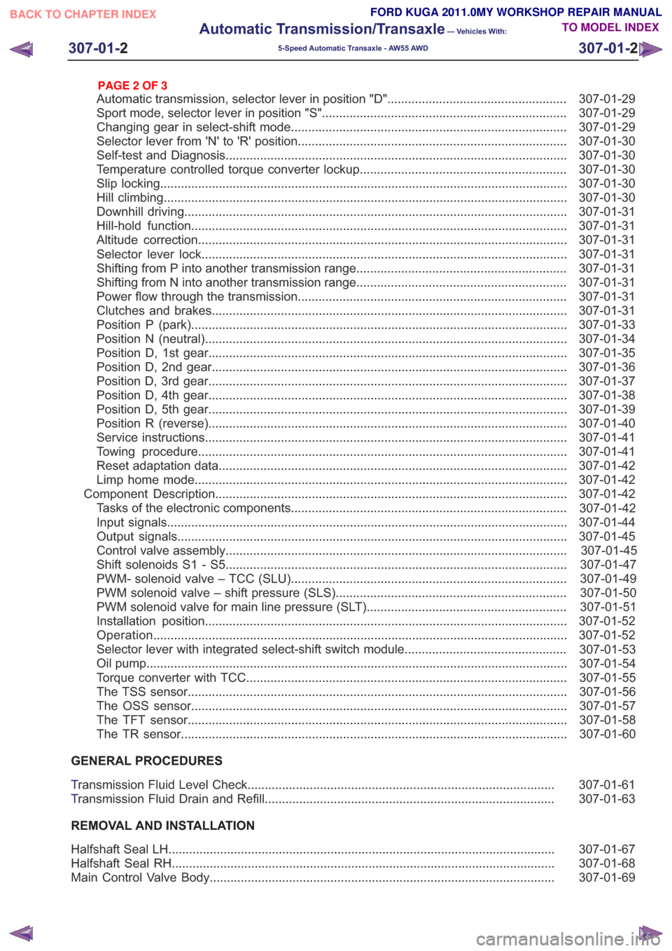
307-01-29
Automatic transmission, selector lever in position "D". ...................................................
307-01-29
Sport mode, selector lever in position "S" .......................................................................
307-01-29
Changing gear in select-shift mode........................................................................\
........
307-01-30
Selector lever from 'N' to 'R' position ........................................................................\
......
307-01-30
Self-test and Diagnosis ........................................................................\
...........................
307-01-30
Temperature controlled torque converter lockup ............................................................
307-01-30
Slip locking ........................................................................\
..............................................
307-01-30
Hill climbing ........................................................................\
.............................................
307-01-31
Downhill driving ........................................................................\
.......................................
307-01-31
Hill-hold function ........................................................................\
.....................................
307-01-31
Altitude correction ........................................................................\
...................................
307-01-31
Selector lever lock ........................................................................\
..................................
307-01-31
Shifting from P into another transmission range .............................................................
307-01-31
Shifting from N into another transmission range .............................................................
307-01-31
Power flow through the transmission ........................................................................\
......
307-01-31
Clutches and brakes ........................................................................\
...............................
307-01-33
Position P (park) ........................................................................\
.....................................
307-01-34
Position N (neutral) ........................................................................\
.................................
307-01-35
Position D, 1st gear........................................................................\
................................
307-01-36
Position D, 2nd gear ........................................................................\
...............................
307-01-37
Position D, 3rd gear ........................................................................\
................................
307-01-38
Position D, 4th gear ........................................................................\
................................
307-01-39
Position D, 5th gear ........................................................................\
................................
307-01-40
Position R (reverse) ........................................................................\
................................
307-01-41
Service instructions ........................................................................\
.................................
307-01-41
Towing procedure ........................................................................\
...................................
307-01-42
Reset adaptation data ........................................................................\
.............................
307-01-42
Limp home mode ........................................................................\
....................................
307-01-42
Component Description ........................................................................\
..............................
Tasks of the electronic components ........................................................................\
........
307-01-44
Input signals ........................................................................\
............................................
307-01-45
Output signals ........................................................................\
.........................................
Control valve assembly ........................................................................\
...........................
Shift solenoids S1 - S5 ........................................................................\
...........................
PWM-
solenoid valve – TCC (SLU) ........................................................................\
........
PWM solenoid valve – shift pressure (SLS) ...................................................................
PWM solenoid valve for main line pressure (SLT) ..........................................................
307-01-52
Installation position ........................................................................\
.................................
Operation ........................................................................\
................................................
Selector lever with integrated select-shift switch module ...............................................
Oil pump ........................................................................\
..................................................
Torque converter with TCC ........................................................................\
.....................
The TSS sensor ........................................................................\
......................................
The OSS sensor ........................................................................\
.....................................
The TFT sensor ........................................................................\
......................................
The TR sensor ........................................................................\
........................................
GENERAL PROCEDURES
T ransmission Fluid Level Check ........................................................................\
.................
307-01-63
T ransmission Fluid Drain and Refill ........................................................................\
............
REMOVAL AND INSTALLATION 307-01-67
Halfshaft Seal LH ........................................................................\
........................................
307-01-68
Halfshaft Seal RH........................................................................\
.......................................
307-01-69
Main Control Valve Body ........................................................................\
............................
307-01-2
Automatic Transmission/Transaxle
— Vehicles With:
5-Speed Automatic Transaxle - AW55 AWD
307-01- 2
.
TO MODEL INDEX
BACK TO CHAPTER INDEX
307-01-42
307-01-49
307-01-52 307-01-47
307-01-45
307-01-50
307-01-51
307-01-53
307-01-55
307-01-54
307-01-56
307-01-57
307-01-58
307-01-61 307-01-60
PAGE 2 OF 3 FORD KUGA 2011.0MY WORKSHOP REPAIR MANUAL
Page 1849 of 2057
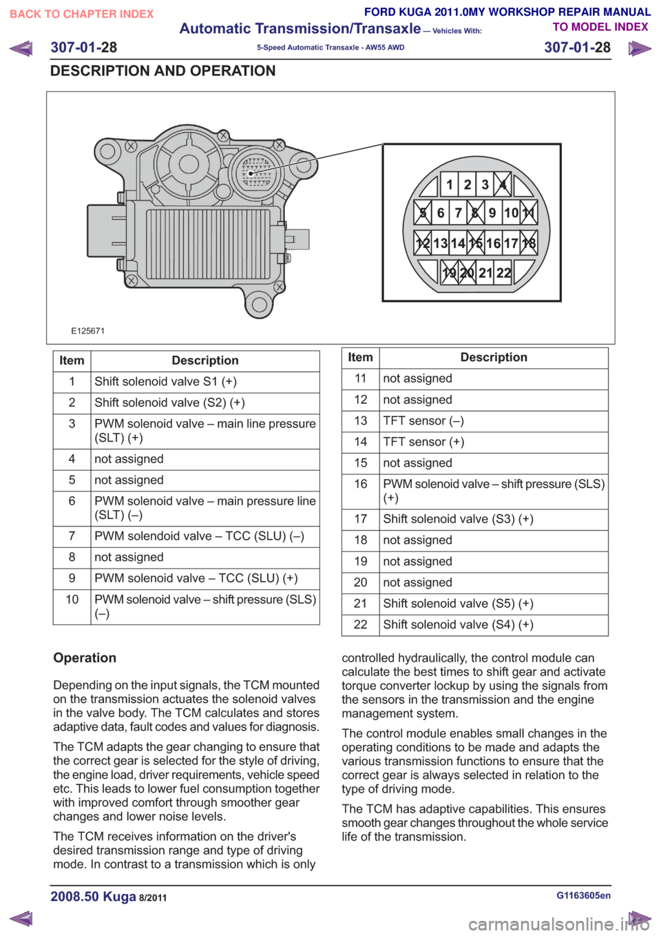
21
22 20 19
15 14 13
161718 12
876
9
10
11 5
3
42121
22 20 19
15 14 13
161718 12
876
9
10
11 5
3
421
E125671
Description
Item
Shift solenoid valve S1 (+)
1
Shift solenoid valve (S2) (+)
2
PWM solenoid valve – main line pressure
(SLT) (+)
3
not assigned
4
not assigned
5
PWM solenoid valve – main pressure line
(SLT) (–)
6
PWM solendoid valve – TCC (SLU) (–)
7
not assigned
8
PWM solenoid valve – TCC (SLU) (+)
9
PWM solenoid valve – shift pressure (SLS)
(–)
10Description
Item
not assigned
11
not assigned
12
TFT sensor (–)
13
TFT sensor (+)
14
not assigned
15
PWM solenoid valve – shift pressure (SLS)
(+)
16
Shift solenoid valve (S3) (+)
17
not assigned
18
not assigned
19
not assigned
20
Shift solenoid valve (S5) (+)
21
Shift solenoid valve (S4) (+)
22
Operation
Depending on the input signals, the TCM mounted
on the transmission actuates the solenoid valves
in the valve body. The TCM calculates and stores
adaptive data, fault codes and values for diagnosis.
The TCM adapts the gear changing to ensure that
the correct gear is selected for the style of driving,
the engine load, driver requirements, vehicle speed
etc. This leads to lower fuel consumption together
with improved comfort through smoother gear
changes and lower noise levels.
The TCM receives information on the driver's
desired transmission range and type of driving
mode. In contrast to a transmission which is only controlled hydraulically, the control module can
calculate the best times to shift gear and activate
torque converter lockup by using the signals from
the sensors in the transmission and the engine
management system.
The control module enables small changes in the
operating conditions to be made and adapts the
various transmission functions to ensure that the
correct gear is always selected in relation to the
type of driving mode.
The TCM has adaptive capabilities. This ensures
smooth gear changes throughout the whole service
life of the transmission.
G1163605en2008.50 Kuga8/2011
307-01-
28
Automatic Transmission/Transaxle
— Vehicles With:
5-Speed Automatic Transaxle - AW55 AWD
307-01- 28
DESCRIPTION AND OPERATION
TO MODEL INDEX
BACK TO CHAPTER INDEX
FORD KUGA 2011.0MY WORKSHOP REPAIR MANUAL
Page 2002 of 2057
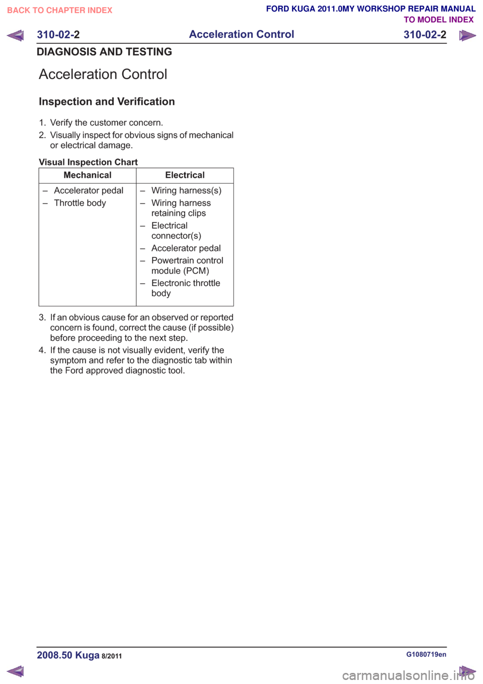
Acceleration Control
Inspection and Verification
1. Verify the customer concern.
2. Visually inspect for obvious signs of mechanicalor electrical damage.
Visual Inspection Chart
Electrical
Mechanical
– Wiring harness(s)
– Wiring harnessretaining clips
– Electrical connector(s)
– Accelerator pedal
– Powertrain control module (PCM)
– Electronic throttle body
– Accelerator pedal
– Throttle body
3. If an obvious cause for an observed or reported concern is found, correct the cause (if possible)
before proceeding to the next step.
4. If the cause is not visually evident, verify the symptom and refer to the diagnostic tab within
the Ford approved diagnostic tool.
G1080719en2008.50 Kuga8/2011
310-02- 2
Acceleration Control
310-02- 2
DIAGNOSIS AND TESTING
TO MODEL INDEX
BACK TO CHAPTER INDEX
FORD KUGA 2011.0MY WORKSHOP REPAIR MANUAL
Page 2007 of 2057
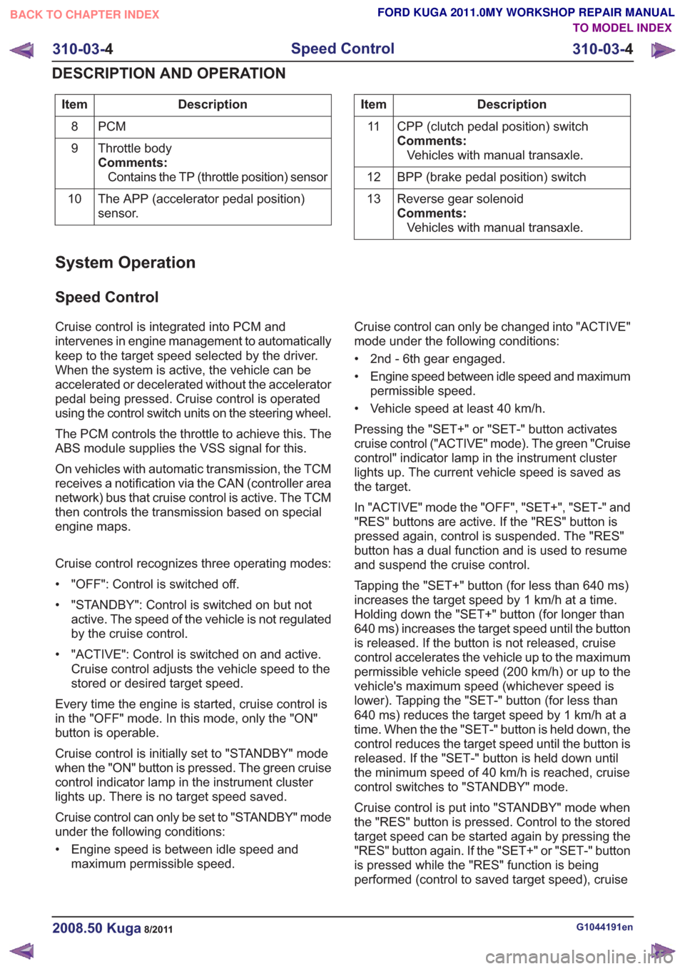
Description
Item
PCM
8
Throttle body
Comments:Contains the TP (throttle position) sensor
9
The APP (accelerator pedal position)
sensor.
10Description
Item
CPP (clutch pedal position) switch
Comments:Vehicles with manual transaxle.
11
BPP (brake pedal position) switch
12
Reverse gear solenoid
Comments:Vehicles with manual transaxle.
13
System Operation
Speed Control
Cruise control is integrated into PCM and
intervenes in engine management to automatically
keep to the target speed selected by the driver.
When the system is active, the vehicle can be
accelerated or decelerated without the accelerator
pedal being pressed. Cruise control is operated
using the control switch units on the steering wheel.
The PCM controls the throttle to achieve this. The
ABS module supplies the VSS signal for this.
On vehicles with automatic transmission, the TCM
receives a notification via the CAN (controller area
network) bus that cruise control is active. The TCM
then controls the transmission based on special
engine maps.
Cruise control recognizes three operating modes:
• "OFF": Control is switched off.
• "STANDBY": Control is switched on but not
active. The speed of the vehicle is not regulated
by the cruise control.
• "ACTIVE": Control is switched on and active. Cruise control adjusts the vehicle speed to the
stored or desired target speed.
Every time the engine is started, cruise control is
in the "OFF" mode. In this mode, only the "ON"
button is operable.
Cruise control is initially set to "STANDBY" mode
when the "ON" button is pressed. The green cruise
control indicator lamp in the instrument cluster
lights up. There is no target speed saved.
Cruise control can only be set to "STANDBY" mode
under the following conditions:
• Engine speed is between idle speed and maximum permissible speed. Cruise control can only be changed into "ACTIVE"
mode under the following conditions:
• 2nd - 6th gear engaged.
• Engine speed between idle speed and maximum
permissible speed.
• Vehicle speed at least 40 km/h.
Pressing the "SET+" or "SET-" button activates
cruise control ("ACTIVE" mode). The green "Cruise
control" indicator lamp in the instrument cluster
lights up. The current vehicle speed is saved as
the target.
In "ACTIVE" mode the "OFF", "SET+", "SET-" and
"RES" buttons are active. If the "RES" button is
pressed again, control is suspended. The "RES"
button has a dual function and is used to resume
and suspend the cruise control.
Tapping the "SET+" button (for less than 640 ms)
increases the target speed by 1 km/h at a time.
Holding down the "SET+" button (for longer than
640 ms) increases the target speed until the button
is released. If the button is not released, cruise
control accelerates the vehicle up to the maximum
permissible vehicle speed (200 km/h) or up to the
vehicle's maximum speed (whichever speed is
lower). Tapping the "SET-" button (for less than
640 ms) reduces the target speed by 1 km/h at a
time. When the the "SET-" button is held down, the
control reduces the target speed until the button is
released. If the "SET-" button is held down until
the minimum speed of 40 km/h is reached, cruise
control switches to "STANDBY" mode.
Cruise control is put into "STANDBY" mode when
the "RES" button is pressed. Control to the stored
target speed can be started again by pressing the
"RES" button again. If the "SET+" or "SET-" button
is pressed while the "RES" function is being
performed (control to saved target speed), cruise
G1044191en2008.50 Kuga8/2011
310-03- 4
Speed Control
310-03- 4
DESCRIPTION AND OPERATION
TO MODEL INDEX
BACK TO CHAPTER INDEX
FORD KUGA 2011.0MY WORKSHOP REPAIR MANUAL