Central junction box FORD KUGA 2011 1.G Workshop Manual
[x] Cancel search | Manufacturer: FORD, Model Year: 2011, Model line: KUGA, Model: FORD KUGA 2011 1.GPages: 2057
Page 190 of 2057
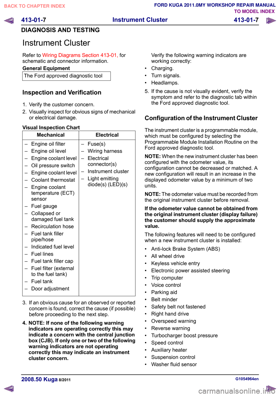
Instrument Cluster
Refer to
Wiring Diagrams Section 413-01, for
schematic and connector information. General Equipment
The Ford approved diagnostic tool
Inspection and Verification
1. Verify the customer concern.
2. Visually inspect for obvious signs of mechanical
or electrical damage.
Visual Inspection Chart Electrical
Mechanical
– Fuse(s)
– Wiring harness
– Electricalconnector(s)
– Instrument cluster
– Light emitting diode(s) (LED)(s)
– Engine oil filter
– Engine oil level
–
Engine coolant level
– Oil pressure switch
– Engine coolant level
– Coolant thermostat
– Engine coolant temperature (ECT)
sensor
– Fuel gauge
– Collapsed or damaged fuel tank
– Recirculation hose
– Fuel tank filler pipe/hose
– Indicated fuel level
– Fuel lines
– Fuel tank filler cap
– Fuel filter (external to the fuel tank)
– Fuel tank
– Door adjustment
3. If an obvious cause for an observed or reported concern is found, correct the cause (if possible)
before proceeding to the next step.
4. NOTE: If none of the following warning indicators are operating correctly this may
indicate a concern with the central junction
box (CJB). If only one or two of the following
warning indicators are not operating
correctly this may indicate an instrument
cluster concern. Verify the following warning indicators are
working correctly:
• Charging.
• Turn signals.
• Headlamps.
5. If the cause is not visually evident, verify the symptom and refer to the diagnostic tab within
the Ford approved diagnostic tool.
Configuration of the Instrument Cluster
The instrument cluster is a programmable module,
which must be configured by selecting the
Programmable Module Installation Routine on the
Ford approved diagnostic tool.
NOTE: When the new instrument cluster has been
configured with the odometer value, its
configuration cannot be decreased or matched. A
new configuration will result in an increase in the
displayed odometer value by a minimum of two
units.
NOTE: The odometer value must be recorded from
the original instrument cluster before removal.
If the odometer value cannot be obtained from
the original instrument cluster (display failure)
the customer should supply the approximate
value.
The following features will need to be configured
when a new instrument cluster is installed:
• Anti-lock Brake System (ABS)
• All wheel drive
• Keyless vehicle entry
• Electronic power assisted steering
• Trip computer
• Voice control
• Parking aid
• Belt minder
• Safety belt not fastened
• Right hand drive
• Overspeed warning
• Reverse warning
• Turbocharger boost pressure
• Speed control
• Auxiliary heater
• Suspension control
• Washer fluid sensor G1054964en
2008.50 Kuga 8/2011 413-01-7
Instrument Cluster
413-01-7
DIAGNOSIS AND TESTINGTO MODEL INDEX
BACK TO CHAPTER INDEX
FORD KUGA 2011.0MY WORKSHOP REPAIR MANUAL
Page 288 of 2057
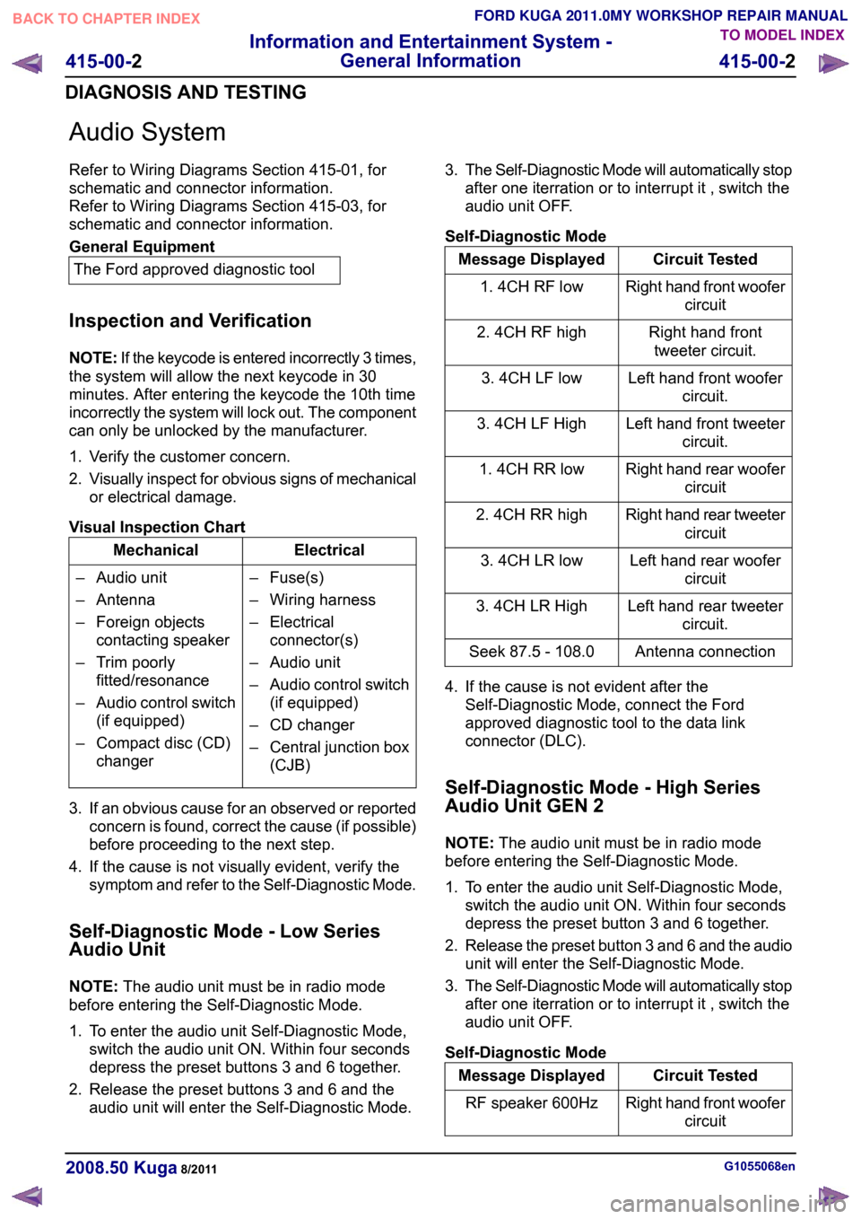
Audio System
Refer to Wiring Diagrams Section 415-01, for
schematic and connector information.
Refer to Wiring Diagrams Section 415-03, for
schematic and connector information.
General Equipment
The Ford approved diagnostic tool
Inspection and Verification
NOTE: If the keycode is entered incorrectly 3 times,
the system will allow the next keycode in 30
minutes. After entering the keycode the 10th time
incorrectly the system will lock out. The component
can only be unlocked by the manufacturer.
1. Verify the customer concern.
2. Visually inspect for obvious signs of mechanical
or electrical damage.
Visual Inspection Chart Electrical
Mechanical
– Fuse(s)
– Wiring harness
– Electricalconnector(s)
– Audio unit
– Audio control switch (if equipped)
– CD changer
– Central junction box (CJB)
– Audio unit
– Antenna
– Foreign objects
contacting speaker
– Trim poorly fitted/resonance
– Audio control switch (if equipped)
– Compact disc (CD) changer
3. If an obvious cause for an observed or reported concern is found, correct the cause (if possible)
before proceeding to the next step.
4. If the cause is not visually evident, verify the symptom and refer to the Self-Diagnostic Mode.
Self-Diagnostic Mode - Low Series
Audio Unit
NOTE: The audio unit must be in radio mode
before entering the Self-Diagnostic Mode.
1. To enter the audio unit Self-Diagnostic Mode, switch the audio unit ON. Within four seconds
depress the preset buttons 3 and 6 together.
2. Release the preset buttons 3 and 6 and the audio unit will enter the Self-Diagnostic Mode. 3.
The Self-Diagnostic Mode will automatically stop
after one iterration or to interrupt it , switch the
audio unit OFF.
Self-Diagnostic Mode Circuit Tested
Message Displayed
Right hand front woofercircuit
1. 4CH RF low
Right hand fronttweeter circuit.
2. 4CH RF high
Left hand front woofercircuit.
3. 4CH LF low
Left hand front tweetercircuit.
3. 4CH LF High
Right hand rear woofercircuit
1. 4CH RR low
Right hand rear tweetercircuit
2. 4CH RR high
Left hand rear woofercircuit
3. 4CH LR low
Left hand rear tweetercircuit.
3. 4CH LR High
Antenna connection
Seek 87.5 - 108.0
4. If the cause is not evident after the Self-Diagnostic Mode, connect the Ford
approved diagnostic tool to the data link
connector (DLC).
Self-Diagnostic Mode - High Series
Audio Unit GEN 2
NOTE: The audio unit must be in radio mode
before entering the Self-Diagnostic Mode.
1. To enter the audio unit Self-Diagnostic Mode, switch the audio unit ON. Within four seconds
depress the preset button 3 and 6 together.
2. Release the preset button 3 and 6 and the audio
unit will enter the Self-Diagnostic Mode.
3. The Self-Diagnostic Mode will automatically stop
after one iterration or to interrupt it , switch the
audio unit OFF.
Self-Diagnostic Mode Circuit Tested
Message Displayed
Right hand front woofercircuit
RF speaker 600Hz G1055068en
2008.50 Kuga 8/2011 415-00-2
Information and Entertainment System -
General Information
415-00-2
DIAGNOSIS AND TESTINGTO MODEL INDEX
BACK TO CHAPTER INDEX
FORD KUGA 2011.0MY WORKSHOP REPAIR MANUAL
Page 347 of 2057
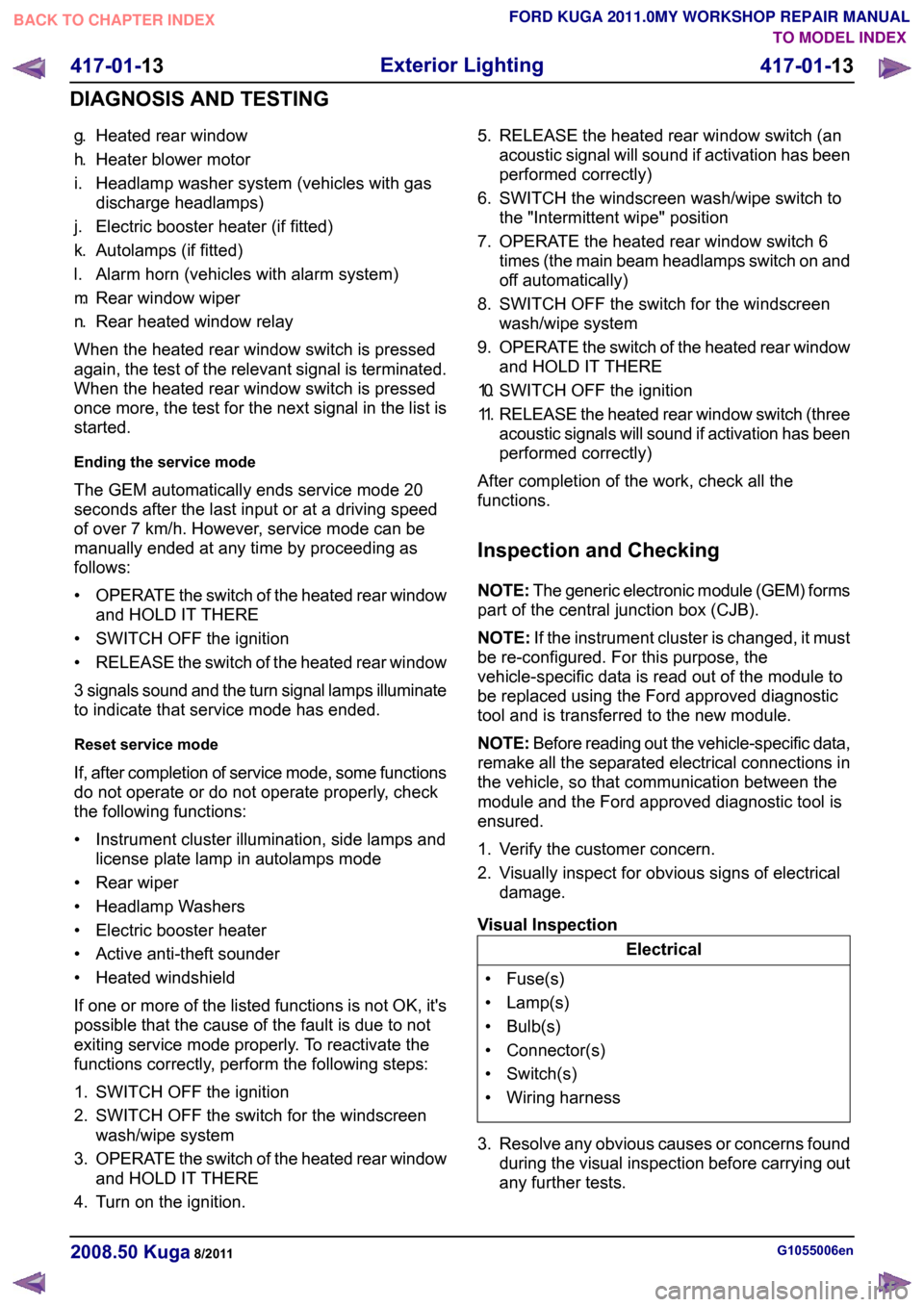
g.
Heated rear window
h. Heater blower motor
i. Headlamp washer system (vehicles with gas discharge headlamps)
j. Electric booster heater (if fitted)
k. Autolamps (if fitted)
l. Alarm horn (vehicles with alarm system)
m. Rear window wiper
n. Rear heated window relay
When the heated rear window switch is pressed
again, the test of the relevant signal is terminated.
When the heated rear window switch is pressed
once more, the test for the next signal in the list is
started.
Ending the service mode
The GEM automatically ends service mode 20
seconds after the last input or at a driving speed
of over 7 km/h. However, service mode can be
manually ended at any time by proceeding as
follows:
• OPERATE the switch of the heated rear window
and HOLD IT THERE
• SWITCH OFF the ignition
• RELEASE the switch of the heated rear window
3 signals sound and the turn signal lamps illuminate
to indicate that service mode has ended.
Reset service mode
If, after completion of service mode, some functions
do not operate or do not operate properly, check
the following functions:
• Instrument cluster illumination, side lamps and license plate lamp in autolamps mode
• Rear wiper
• Headlamp Washers
• Electric booster heater
• Active anti-theft sounder
• Heated windshield
If one or more of the listed functions is not OK, it's
possible that the cause of the fault is due to not
exiting service mode properly. To reactivate the
functions correctly, perform the following steps:
1. SWITCH OFF the ignition
2. SWITCH OFF the switch for the windscreen wash/wipe system
3. OPERATE the switch of the heated rear window
and HOLD IT THERE
4. Turn on the ignition. 5. RELEASE the heated rear window switch (an
acoustic signal will sound if activation has been
performed correctly)
6. SWITCH the windscreen wash/wipe switch to the "Intermittent wipe" position
7. OPERATE the heated rear window switch 6 times (the main beam headlamps switch on and
off automatically)
8. SWITCH OFF the switch for the windscreen wash/wipe system
9. OPERATE the switch of the heated rear window
and HOLD IT THERE
10. SWITCH OFF the ignition
11. RELEASE the heated rear window switch (three
acoustic signals will sound if activation has been
performed correctly)
After completion of the work, check all the
functions.
Inspection and Checking
NOTE: The generic electronic module (GEM) forms
part of the central junction box (CJB).
NOTE: If the instrument cluster is changed, it must
be re-configured. For this purpose, the
vehicle-specific data is read out of the module to
be replaced using the Ford approved diagnostic
tool and is transferred to the new module.
NOTE: Before reading out the vehicle-specific data,
remake all the separated electrical connections in
the vehicle, so that communication between the
module and the Ford approved diagnostic tool is
ensured.
1. Verify the customer concern.
2. Visually inspect for obvious signs of electrical damage.
Visual Inspection Electrical
• Fuse(s)
• Lamp(s)
• Bulb(s)
• Connector(s)
• Switch(s)
• Wiring harness
3. Resolve any obvious causes or concerns found during the visual inspection before carrying out
any further tests. G1055006en
2008.50 Kuga 8/2011 417-01-13
Exterior Lighting
417-01-13
DIAGNOSIS AND TESTINGTO MODEL INDEX
BACK TO CHAPTER INDEX
FORD KUGA 2011.0MY WORKSHOP REPAIR MANUAL
Page 350 of 2057
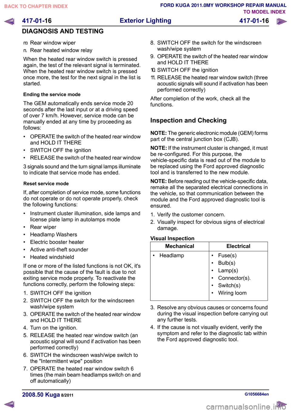
m.
Rear window wiper
n. Rear heated window relay
When the heated rear window switch is pressed
again, the test of the relevant signal is terminated.
When the heated rear window switch is pressed
once more, the test for the next signal in the list is
started.
Ending the service mode
The GEM automatically ends service mode 20
seconds after the last input or at a driving speed
of over 7 km/h. However, service mode can be
manually ended at any time by proceeding as
follows:
• OPERATE the switch of the heated rear window
and HOLD IT THERE
• SWITCH OFF the ignition
• RELEASE the switch of the heated rear window
3 signals sound and the turn signal lamps illuminate
to indicate that service mode has ended.
Reset service mode
If, after completion of service mode, some functions
do not operate or do not operate properly, check
the following functions:
• Instrument cluster illumination, side lamps and license plate lamp in autolamps mode
• Rear wiper
• Headlamp Washers
• Electric booster heater
• Active anti-theft sounder
• Heated windshield
If one or more of the listed functions is not OK, it's
possible that the cause of the fault is due to not
exiting service mode properly. To reactivate the
functions correctly, perform the following steps:
1. SWITCH OFF the ignition
2. SWITCH OFF the switch for the windscreen wash/wipe system
3. OPERATE the switch of the heated rear window
and HOLD IT THERE
4. Turn on the ignition.
5. RELEASE the heated rear window switch (an acoustic signal will sound if activation has been
performed correctly)
6. SWITCH the windscreen wash/wipe switch to the "Intermittent wipe" position
7. OPERATE the heated rear window switch 6 times (the main beam headlamps switch on and
off automatically) 8. SWITCH OFF the switch for the windscreen
wash/wipe system
9. OPERATE the switch of the heated rear window
and HOLD IT THERE
10. SWITCH OFF the ignition
11. RELEASE the heated rear window switch (three
acoustic signals will sound if activation has been
performed correctly)
After completion of the work, check all the
functions.
Inspection and Checking
NOTE: The generic electronic module (GEM) forms
part of the central junction box (CJB).
NOTE: If the instrument cluster is changed, it must
be re-configured. For this purpose, the
vehicle-specific data is read out of the module to
be replaced using the Ford approved diagnostic
tool and is transferred to the new module.
NOTE: Before reading out the vehicle-specific data,
remake all the separated electrical connections in
the vehicle, so that communication between the
module and the Ford approved diagnostic tool is
ensured.
1. Verify the customer concern.
2. Visually inspect for obvious signs of electrical damage.
Visual Inspection Electrical
Mechanical
• Fuse(s)
• Bulb(s)
• Lamp(s)
• Connector(s).
• Switch(s)
• Wiring loom
• Headlamp
3. Resolve any obvious causes or concerns found during the visual inspection before carrying out
any further tests.
4. If the cause is not visually evident, verify the symptom and refer to the diagnostic tab within
the Ford approved diagnostic tool. G1056684en
2008.50 Kuga 8/2011 417-01-16
Exterior Lighting
417-01-16
DIAGNOSIS AND TESTINGTO MODEL INDEX
BACK TO CHAPTER INDEX
FORD KUGA 2011.0MY WORKSHOP REPAIR MANUAL
Page 352 of 2057
g.
Heated rear window
h. Heater blower motor
i. Headlamp washer system (vehicles with gas discharge headlamps)
j. Electric booster heater (if fitted)
k. Autolamps (if fitted)
l. Alarm horn (vehicles with alarm system)
m. Rear window wiper
n. Rear heated window relay
When the heated rear window switch is pressed
again, the test of the relevant signal is terminated.
When the heated rear window switch is pressed
once more, the test for the next signal in the list is
started.
Ending the service mode
The GEM automatically ends service mode 20
seconds after the last input or at a driving speed
of over 7 km/h. However, service mode can be
manually ended at any time by proceeding as
follows:
• OPERATE the switch of the heated rear window
and HOLD IT THERE
• SWITCH OFF the ignition
• RELEASE the switch of the heated rear window
3 signals sound and the turn signal lamps illuminate
to indicate that service mode has ended.
Reset service mode
If, after completion of service mode, some functions
do not operate or do not operate properly, check
the following functions:
• Instrument cluster illumination, side lamps and license plate lamp in autolamps mode
• Rear wiper
• Headlamp Washers
• Electric booster heater
• Active anti-theft sounder
• Heated windshield
If one or more of the listed functions is not OK, it's
possible that the cause of the fault is due to not
exiting service mode properly. To reactivate the
functions correctly, perform the following steps:
1. SWITCH OFF the ignition
2. SWITCH OFF the switch for the windscreen wash/wipe system
3. OPERATE the switch of the heated rear window
and HOLD IT THERE
4. Turn on the ignition. 5. RELEASE the heated rear window switch (an
acoustic signal will sound if activation has been
performed correctly)
6. SWITCH the windscreen wash/wipe switch to the "Intermittent wipe" position
7. OPERATE the heated rear window switch 6 times (the main beam headlamps switch on and
off automatically)
8. SWITCH OFF the switch for the windscreen wash/wipe system
9. OPERATE the switch of the heated rear window
and HOLD IT THERE
10. SWITCH OFF the ignition
11. RELEASE the heated rear window switch (three
acoustic signals will sound if activation has been
performed correctly)
After completion of the work, check all the
functions.
Inspection and Checking
NOTE: The generic electronic module (GEM) forms
part of the central junction box (CJB).
NOTE: Before reading out the vehicle-specific data,
remake all the separated electrical connections in
the vehicle, so that communication between the
module and the Ford approved diagnostic tool is
ensured.
1. Verify the customer concern.
2. Visually inspect for obvious signs of electrical (or mechanical) damage.
Visual Inspection Electrical
Mechanical
• Fuse(s)
• Connector(s).
• Switch(s)
• Wiring loom
• Headlamp levellingsensors
• Gas discharge headlamp control
module
• Headlamp
• Headlamp adjuster
unit
3. Resolve any obvious causes or concerns found d#uring the visual inspection before carrying out
any further tests.
4. If the cause is not visually evident, verify the symptom and refer to the diagnostic tab within
the Ford approved diagnostic tool. G1055012en
2008.50 Kuga 8/2011 417-01-18
Exterior Lighting
417-01-18
DIAGNOSIS AND TESTINGTO MODEL INDEX
BACK TO CHAPTER INDEX
FORD KUGA 2011.0MY WORKSHOP REPAIR MANUAL
Page 354 of 2057
g.
Heated rear window
h. Heater blower motor
i. Headlamp washer system (vehicles with gas discharge headlamps)
j. Electric booster heater (if fitted)
k. Autolamps (if fitted)
l. Alarm horn (vehicles with alarm system)
m. Rear window wiper
n. Rear heated window relay
When the heated rear window switch is pressed
again, the test of the relevant signal is terminated.
When the heated rear window switch is pressed
once more, the test for the next signal in the list is
started.
Ending the service mode
The GEM automatically ends service mode 20
seconds after the last input or at a driving speed
of over 7 km/h. However, service mode can be
manually ended at any time by proceeding as
follows:
• OPERATE the switch of the heated rear window
and HOLD IT THERE
• SWITCH OFF the ignition
• RELEASE the switch of the heated rear window
3 signals sound and the turn signal lamps illuminate
to indicate that service mode has ended.
Reset service mode
If, after completion of service mode, some functions
do not operate or do not operate properly, check
the following functions:
• Instrument cluster illumination, side lamps and license plate lamp in autolamps mode
• Rear wiper
• Headlamp Washers
• Electric booster heater
• Active anti-theft sounder
• Heated windshield
If one or more of the listed functions is not OK, it's
possible that the cause of the fault is due to not
exiting service mode properly. To reactivate the
functions correctly, perform the following steps:
1. SWITCH OFF the ignition
2. SWITCH OFF the switch for the windscreen wash/wipe system
3. OPERATE the switch of the heated rear window
and HOLD IT THERE
4. Turn on the ignition. 5. RELEASE the heated rear window switch (an
acoustic signal will sound if activation has been
performed correctly)
6. SWITCH the windscreen wash/wipe switch to the "Intermittent wipe" position
7. OPERATE the heated rear window switch 6 times (the main beam headlamps switch on and
off automatically)
8. SWITCH OFF the switch for the windscreen wash/wipe system
9. OPERATE the switch of the heated rear window
and HOLD IT THERE
10. SWITCH OFF the ignition
11. RELEASE the heated rear window switch (three
acoustic signals will sound if activation has been
performed correctly)
After completion of the work, check all the
functions.
Inspection and Checking
NOTE: The generic electronic module (GEM) forms
part of the central junction box (CJB).
NOTE: Before reading out the vehicle-specific data,
remake all the electrical connections which were
separated in the vehicle, so that communication
between the module and the Ford approved
diagnostic tool is ensured.
1. Verify the customer concern.
2. Visually check the following electrical causes for the concern:
Visual Inspection Electrical
• Fuse(s)
• Bulb(s)
• Lamp(s)
• Connector(s).
• Switches
• Wiring loom
3. Resolve any obvious causes or concerns found during the visual inspection before carrying out
any further tests.
4. If the cause is not visually evident, verify the symptom and refer to the diagnostic tab within
the Ford approved diagnostic tool. G1055004en
2008.50 Kuga 8/2011 417-01-20
Exterior Lighting
417-01-20
DIAGNOSIS AND TESTINGTO MODEL INDEX
BACK TO CHAPTER INDEX
FORD KUGA 2011.0MY WORKSHOP REPAIR MANUAL
Page 356 of 2057
e.
Windshield wiper stage I
f. Windshield wiper stage II
g. Heated rear window
h. Heater blower motor
i. Headlamp washer system (vehicles with gas discharge headlamps)
j. Electric booster heater (if fitted)
k. Autolamps (if fitted)
l. Alarm horn (vehicles with alarm system)
m. Rear window wiper
n. Rear heated window relay
When the heated rear window switch is pressed
again, the test of the relevant signal is terminated.
When the heated rear window switch is pressed
once more, the test for the next signal in the list is
started.
Ending the service mode
The GEM automatically ends service mode 20
seconds after the last input or at a driving speed
of over 7 km/h. However, service mode can be
manually ended at any time by proceeding as
follows:
• OPERATE the switch of the heated rear window
and HOLD IT THERE
• SWITCH OFF the ignition
• RELEASE the switch of the heated rear window
3 signals sound and the turn signal lamps illuminate
to indicate that service mode has ended.
Reset service mode
If, after completion of service mode, some functions
do not operate or do not operate properly, check
the following functions:
• Instrument cluster illumination, side lamps and license plate lamp in autolamps mode
• Rear wiper
• Headlamp Washers
• Electric booster heater
• Active anti-theft sounder
• Heated windshield
If one or more of the listed functions is not OK, it's
possible that the cause of the fault is due to not
exiting service mode properly. To reactivate the
functions correctly, perform the following steps:
1. SWITCH OFF the ignition
2. SWITCH OFF the switch for the windscreen wash/wipe system 3.
OPERATE the switch of the heated rear window
and HOLD IT THERE
4. Turn on the ignition.
5. RELEASE the heated rear window switch (an acoustic signal will sound if activation has been
performed correctly)
6. SWITCH the windscreen wash/wipe switch to the "Intermittent wipe" position
7. OPERATE the heated rear window switch 6 times (the main beam headlamps switch on and
off automatically)
8. SWITCH OFF the switch for the windscreen wash/wipe system
9. OPERATE the switch of the heated rear window
and HOLD IT THERE
10. SWITCH OFF the ignition
11. RELEASE the heated rear window switch (three
acoustic signals will sound if activation has been
performed correctly)
After completion of the work, check all the
functions.
Inspection and Checking
NOTE: The generic electronic module (GEM) forms
part of the central junction box (CJB).
NOTE: If the generic electronic module (GEM) is
changed, the new one must be reconfigured. For
this purpose, the vehicle-specific data is read out
of the module to be replaced using the Ford
approved diagnostic tool and is transferred to the
new module. REFER to: (418-00 Module
Communications Network)
Communications Network (Description and
Operation),
Communications Network (Description and
Operation).
NOTE: Before reading out the vehicle-specific data,
remake all the electrical connections which were
separated in the vehicle, so that communication
between the module and the Ford approved
diagnostic tool is ensured.
1. Verify the customer concern.
2. Visually inspect for obvious signs of electrical damage:
NOTE: Ensure correct engagement of the wiring
harness connectors. G1055008en
2008.50 Kuga 8/2011 417-01-22
Exterior Lighting
417-01-22
DIAGNOSIS AND TESTINGTO MODEL INDEX
BACK TO CHAPTER INDEX
FORD KUGA 2011.0MY WORKSHOP REPAIR MANUAL
Page 359 of 2057
When the heated rear window switch is pressed
again, the test of the relevant signal is terminated.
When the heated rear window switch is pressed
once more, the test for the next signal in the list is
started.
Ending the service mode
The GEM automatically ends service mode 20
seconds after the last input or at a driving speed
of over 7 km/h. However, service mode can be
manually ended at any time by proceeding as
follows:
•
OPERATE the switch of the heated rear window
and HOLD IT THERE
• SWITCH OFF the ignition
• RELEASE the switch of the heated rear window
3 signals sound and the turn signal lamps illuminate
to indicate that service mode has ended.
Reset service mode
If, after completion of service mode, some functions
do not operate or do not operate properly, check
the following functions:
• Instrument cluster illumination, side lamps and license plate lamp in autolamps mode
• Rear wiper
• Headlamp Washers
• Electric booster heater
• Active anti-theft sounder
• Heated windshield
If one or more of the listed functions is not OK, it's
possible that the cause of the fault is due to not
exiting service mode properly. To reactivate the
functions correctly, perform the following steps:
1. SWITCH OFF the ignition
2. SWITCH OFF the switch for the windscreen wash/wipe system
3. OPERATE the switch of the heated rear window
and HOLD IT THERE
4. Turn on the ignition.
5. RELEASE the heated rear window switch (an acoustic signal will sound if activation has been
performed correctly)
6. SWITCH the windscreen wash/wipe switch to the "Intermittent wipe" position
7. OPERATE the heated rear window switch 6 times (the main beam headlamps switch on and
off automatically)
8. SWITCH OFF the switch for the windscreen wash/wipe system 9.
OPERATE the switch of the heated rear window
and HOLD IT THERE
10. SWITCH OFF the ignition
11. RELEASE the heated rear window switch (three
acoustic signals will sound if activation has been
performed correctly)
After completion of the work, check all the
functions.
Inspection and Checking
NOTE: The generic electronic module (GEM) forms
part of the central junction box (CJB).
NOTE: If the instrument cluster is changed, it must
be re-configured. For this purpose, the
vehicle-specific data is read out of the module to
be replaced using the Ford approved diagnostic
tool and is transferred to the new module.
NOTE: Before reading out the vehicle-specific data,
remake all the separated electrical connections in
the vehicle, so that communication between the
module and the Ford approved diagnostic tool is
ensured.
1. Verify the customer concern.
2. Visually inspect for obvious signs of electrical damage.
Visual Inspection Electrical
• Fuse(s)
• Lamp(s)
• Bulb(s)
• Connector(s)
• Switches
• Wiring harness
3. Resolve any obvious causes or concerns found during the visual inspection before carrying out
any further tests.
4. If the cause is not visually evident, verify the symptom and refer to the diagnostic tab within
the Ford approved diagnostic tool. G1056685en
2008.50 Kuga 8/2011 417-01-25
Exterior Lighting
417-01-25
DIAGNOSIS AND TESTINGTO MODEL INDEX
BACK TO CHAPTER INDEX
FORD KUGA 2011.0MY WORKSHOP REPAIR MANUAL
Page 361 of 2057
e.
Windshield wiper stage I
f. Windshield wiper stage II
g. Heated rear window
h. Heater blower motor
i. Headlamp washer system (vehicles with gas discharge headlamps)
j. Electric booster heater (if fitted)
k. Automatic headlamps (if equipped)
l. Alarm horn (vehicles with alarm system)
m. Rear window wiper
n. Rear heated window relay
When the heated rear window switch is pressed
again, the test of the relevant signal is terminated.
When the heated rear window switch is pressed
once more, the test for the next signal in the list is
started.
Ending the service mode
The GEM automatically ends service mode 20
seconds after the last input or at a driving speed
of over 7 km/h. However, service mode can be
manually ended at any time by proceeding as
follows:
• OPERATE the switch of the heated rear window
and HOLD IT THERE
• SWITCH OFF the ignition
• RELEASE the switch of the heated rear window
3 signals sound and the turn signal lamps illuminate
to indicate that service mode has ended.
Reset service mode
If, after completion of service mode, some functions
do not operate or do not operate properly, check
the following functions:
• Instrument cluster illumination, side lamps and license plate lamp in autolamps mode
• Rear wiper
• Headlamp Washers
• Electric booster heater
• Active anti-theft sounder
• Heated windshield
If one or more of the listed functions is not OK, it's
possible that the cause of the fault is due to not
exiting service mode properly. To reactivate the
functions correctly, perform the following steps:
1. SWITCH OFF the ignition
2. SWITCH OFF the switch for the windscreen wash/wipe system 3.
OPERATE the switch of the heated rear window
and HOLD IT THERE
4. Turn on the ignition.
5. RELEASE the heated rear window switch (an acoustic signal will sound if activation has been
performed correctly)
6. SWITCH the windscreen wash/wipe switch to the "Intermittent wipe" position
7. OPERATE the heated rear window switch 6 times (the main beam headlamps switch on and
off)
8. SWITCH OFF the switch for the windscreen wash/wipe system
9. OPERATE the switch of the heated rear window
and HOLD IT THERE
10. SWITCH OFF the ignition
11. RELEASE the heated rear window switch (three
acoustic signals will sound if activation has been
performed correctly)
After completion of the work, check all the
functions.
Inspection and Checking
NOTE: The generic electronic module (GEM) forms
part of the central junction box (CJB).
NOTE: If the generic electronic module (GEM) is
changed, the new one must be reconfigured. For
this purpose, the vehicle-specific data is read out
of the module to be replaced using the Ford
approved diagnostic tool and is transferred to the
new module.
NOTE: Before reading out the vehicle-specific data,
remake all the electrical connections which were
separated in the vehicle, so that communication
between the module and the Ford approved
diagnostic tool is ensured.
1. Verify the customer concern.
2. Visually inspect for obvious signs of electrical damage.
Visual Inspection Electrical
• Fuse(s)
• Lamp(s)
• Connector(s).
• Switches
• Wiring harness G1055002en
2008.50 Kuga 8/2011 417-01-27
Exterior Lighting
417-01-27
DIAGNOSIS AND TESTINGTO MODEL INDEX
BACK TO CHAPTER INDEX
FORD KUGA 2011.0MY WORKSHOP REPAIR MANUAL
Page 374 of 2057
Interior Lighting
Refer to
Wiring Diagrams Section 417-02, for
schematic and connector information. General Equipment
The Ford approved diagnostic tool
Inspection and Verification
1. Verify the customer concern.
2. Visually inspect for obvious signs of electrical damage.
Visual Inspection Chart Electrical
– Fuse(s)
– Bulb(s)
– Switch(es)
– Wiring harness
– Electrical connector(s)
– Interior lamp(s)
– Battery saver relay
– Door
– Central junction box (CJB)
3. If an obvious cause for an observed or reported concern is found, correct the cause (if possible)
before proceeding to the next step.
4. If the cause is not visually evident, verify the symptom and refer to the diagnostic tab within
the Ford approved diagnostic tool. G1055016en
2008.50 Kuga 8/2011 417-02-2
Interior Lighting
417-02-2
DIAGNOSIS AND TESTINGTO MODEL INDEX
BACK TO CHAPTER INDEX
FORD KUGA 2011.0MY WORKSHOP REPAIR MANUAL