Central junction box FORD KUGA 2011 1.G User Guide
[x] Cancel search | Manufacturer: FORD, Model Year: 2011, Model line: KUGA, Model: FORD KUGA 2011 1.GPages: 2057
Page 377 of 2057
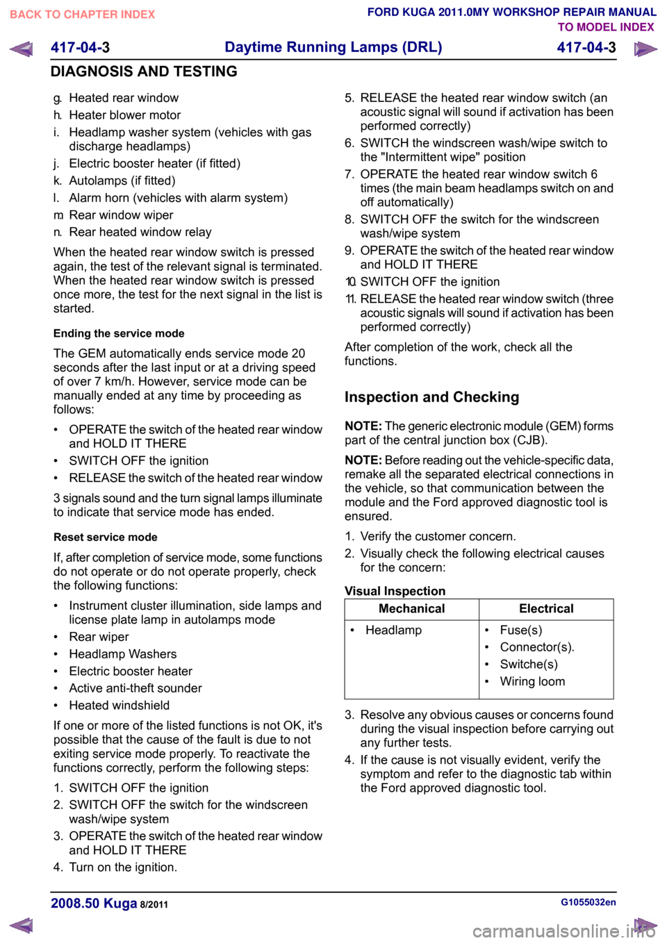
g.
Heated rear window
h. Heater blower motor
i. Headlamp washer system (vehicles with gas discharge headlamps)
j. Electric booster heater (if fitted)
k. Autolamps (if fitted)
l. Alarm horn (vehicles with alarm system)
m. Rear window wiper
n. Rear heated window relay
When the heated rear window switch is pressed
again, the test of the relevant signal is terminated.
When the heated rear window switch is pressed
once more, the test for the next signal in the list is
started.
Ending the service mode
The GEM automatically ends service mode 20
seconds after the last input or at a driving speed
of over 7 km/h. However, service mode can be
manually ended at any time by proceeding as
follows:
• OPERATE the switch of the heated rear window
and HOLD IT THERE
• SWITCH OFF the ignition
• RELEASE the switch of the heated rear window
3 signals sound and the turn signal lamps illuminate
to indicate that service mode has ended.
Reset service mode
If, after completion of service mode, some functions
do not operate or do not operate properly, check
the following functions:
• Instrument cluster illumination, side lamps and license plate lamp in autolamps mode
• Rear wiper
• Headlamp Washers
• Electric booster heater
• Active anti-theft sounder
• Heated windshield
If one or more of the listed functions is not OK, it's
possible that the cause of the fault is due to not
exiting service mode properly. To reactivate the
functions correctly, perform the following steps:
1. SWITCH OFF the ignition
2. SWITCH OFF the switch for the windscreen wash/wipe system
3. OPERATE the switch of the heated rear window
and HOLD IT THERE
4. Turn on the ignition. 5. RELEASE the heated rear window switch (an
acoustic signal will sound if activation has been
performed correctly)
6. SWITCH the windscreen wash/wipe switch to the "Intermittent wipe" position
7. OPERATE the heated rear window switch 6 times (the main beam headlamps switch on and
off automatically)
8. SWITCH OFF the switch for the windscreen wash/wipe system
9. OPERATE the switch of the heated rear window
and HOLD IT THERE
10. SWITCH OFF the ignition
11. RELEASE the heated rear window switch (three
acoustic signals will sound if activation has been
performed correctly)
After completion of the work, check all the
functions.
Inspection and Checking
NOTE: The generic electronic module (GEM) forms
part of the central junction box (CJB).
NOTE: Before reading out the vehicle-specific data,
remake all the separated electrical connections in
the vehicle, so that communication between the
module and the Ford approved diagnostic tool is
ensured.
1. Verify the customer concern.
2. Visually check the following electrical causes for the concern:
Visual Inspection Electrical
Mechanical
• Fuse(s)
• Connector(s).
• Switche(s)
• Wiring loom
• Headlamp
3. Resolve any obvious causes or concerns found during the visual inspection before carrying out
any further tests.
4. If the cause is not visually evident, verify the symptom and refer to the diagnostic tab within
the Ford approved diagnostic tool. G1055032en
2008.50 Kuga 8/2011 417-04-3
Daytime Running Lamps (DRL)
417-04-3
DIAGNOSIS AND TESTINGTO MODEL INDEX
BACK TO CHAPTER INDEX
FORD KUGA 2011.0MY WORKSHOP REPAIR MANUAL
Page 385 of 2057
systems depends on the equipment level of the
vehicle.
In order to guarantee a high degree of error
protection, two 120 Ohm terminating resistors are
installed in the CAN. These are integrated in the
first module connected to the CAN and in the last
module connected to the CAN respectively and
are used for suppression as well as the elimination
of voltage peaks. In order to ensure correct
functioning of the data bus system, the modules
must always be connected with an integral
terminating resistor. In order to enable
communication between the modules on the
HS-CAN and the modules on the MS-CAN, one
module is connected to both data bus systems.
The connection of both data bus systems is
designated as a gateway. In this gateway, the
received data is converted to the transmission rate
required for the relevant data bus and is
transmitted. This ensures an optimal distribution
of information between both data bus systems.
Component Description
ABS
The GEM is integrated in the CJB (central junction
box) and cannot be replaced as a separate unit.
G1030779en
2008.50 Kuga 8/2011 418-00-8
Module Communications Network
418-00-8
DESCRIPTION AND OPERATIONTO MODEL INDEX
BACK TO CHAPTER INDEX
FORD KUGA 2011.0MY WORKSHOP REPAIR MANUAL
Page 452 of 2057
Module Controlled Functions – Overview
Generic electronics module (GEM)
CAUTIONS:
Never swap the GEM (generic electronic
module) between two vehicles.
Compare the number of relays and fuses
in the defective GEM and the new GEM.
Transfer from the defective GEM any relays
and fuses which are not in the new GEM.
In doing so, pay attention that fuses with
the correct Ampere rating are used, by
referring to the wiring diagrams.
NOTE: The GEM is integrated in the CJB (central
junction box) and cannot be replaced as a separate
unit.
For repair work during a service, vehicle-specific
configuration is necessary if a new GEM is
installed.
Emergency function
The GEM is equipped with restricted emergency
running functions on vehicles with mid or high-end
equipment levels.
The microcontroller sends a control signal to a
monitoring function within the GEM at regular
intervals. If the battery voltage falls below a value
of approx. 7.5 volts, this check signal is not present
and the GEM switches to emergency function after
a predetermined time.
In this case, the low beam is permanently switched
on, regardless of the light switch position. The
windshield wiper can only be operated in stage 1;
the wiper switch must however be in the stage I or
II position. The wiper park position is not
recognized. Intermittent wiping is not available.
When the control signal recurs, the GEM switches
back to normal operation.
Service mode
Description of operation
Diagnosis of the GEM can be carried out using the
Ford diagnostic unit. Furthermore, an integrated
service mode enables testing of the input and
output signals without the need for further tools.
To enable activation of service mode: • switch off the ignition,
• switch off all other electrical consumers,
• apply the handbrake,
• Shift to neutral
• and close the doors.
Activating the service mode
NOTE:
If the alarm is activated (in vehicles fitted
with an anti-theft alarm system), service mode
cannot be activated.
Proceed as follows to activate the service mode:
• OPERATE the switch of the heated rear window
and HOLD IT THERE
• SWITCH ON the ignition.
• RELEASE the switch of the heated rear window
A signal sounds and the turn signal lamps come
on to indicate that service mode has been
successfully activated.
Inputs
SWITCH the windshield wiper switch to the "OFF"
position to test the input signals. The following is
a list of the switch signals to be tested, in no
particular order:
• Windshield wiper stage I
• Windshield wiper stage II
• Windshield washer system
• Rear window wiper
• Rear window washer system
• Doors open/closed
• Remote control for central locking with double locking
• Hood open/closed (in vehicles equipped with an anti-theft alarm system)
• Tailgate open/closed
• A/C request signal
• Heated windscreen (if fitted)
• Parking brake
• Brake fluid level
• Cruise control system
• Autolamps
• Dipped beam
• Main beam
• Headlamp flasher
• Side lights
• Turn signals (right, left, hazard warning lights) G1030787en
2008.50 Kuga 8/2011 419-10-2
Multifunction Electronic Modules
419-10-2
DESCRIPTION AND OPERATIONTO MODEL INDEX
BACK TO CHAPTER INDEX
FORD KUGA 2011.0MY WORKSHOP REPAIR MANUAL
Page 462 of 2057
Output signals
SWITCH the wiper switch to the "intermittent""
position to test the output signals. PRESSING the
heated rear window switch activates the output
signals in the following order:
a.
Left-hand turn signal
b. Right-hand turn signal
c. Main beam
d. Dipped beam
e. Windshield wiper stage I
f. Windshield wiper stage II
g. Heated rear windshield
h. Heater blower motor
i. Headlamp washer system (vehicles with HID headlamps)
j. Electric booster heater (if fitted)
k. Autolamps (position lamps only if fitted)
l. Alarm horn (vehicles with alarm system)
m. Rear window wiper
n. Heated front window relay
When the heated rear window switch is pressed
again, the test of the relevant signal is terminated.
When the heated rear window switch is pressed
once more, the test for the next signal in the list is
started.
End service mode
The GEM automatically ends service mode 20
seconds after the last input or at a driving speed
of over 7km/h. However, service mode can be
manually ended at any time by proceeding as
follows:
• PRESS and HOLD the switch of the heated rear
window
• SWITCH OFF the ignition.
• RELEASE the switch of the heated rear window
3 signals sound and the turn signal lamps illuminate
to indicate that service mode has ended.
Reset service mode
If, after completion of service mode, some functions
do not operate or do not operate properly, check
the following functions:
• Instrument cluster illumination, side marker lamps (side lights) and licence plate lamp in
automatic headlamps mode
• Rear wiper
• Headlamp washer assembly
• Electric booster heater • Alarm horn
• Heated windshield
If one or more of the listed functions is not OK, it's
possible that the cause of the fault is due to not
exiting service mode properly. To reactivate the
functions correctly, perform the following steps:
1. Switch off the ignition.
2. SWITCH OFF the switch for the windscreen
wash/wipe system
3. OPERATE the switch of the heated rear window
and HOLD IT THERE
4. SWITCH ON the ignition.
5. RELEASE the heated rear window switch (an acoustic signal will sound if activation has been
performed correctly)
6. SWITCH the windscreen wash/wipe switch to the "Intermittent wipe" position
7. OPERATE the heated rear window switch 6 times (the main beam headlamps switch on and
off automatically)
8. SWITCH OFF the switch for the windscreen wash/wipe system
9. OPERATE the switch of the heated rear window
and HOLD IT THERE
10. Switch off the ignition.
11. RELEASE the heated rear window switch (three
acoustic signals will sound if activation has been
performed correctly)
After completion of the work, check all the
functions.
Inspection and Checking
NOTE: The generic electronic module (GEM) is
integrated into the central junction box (CJB).
1. VERIFY customer concern.
2. Visually CHECK for any obvious mechanical or electrical damage.
NOTE: Ensure correct locking of the wiring harness
connector.
Visual Inspection Electrical
Fuses
Wiring harness Connectors G1055084en
2008.50 Kuga 8/2011 419-10-12
Multifunction Electronic Modules
419-10-12
DIAGNOSIS AND TESTINGTO MODEL INDEX
BACK TO CHAPTER INDEX
FORD KUGA 2011.0MY WORKSHOP REPAIR MANUAL
Page 464 of 2057
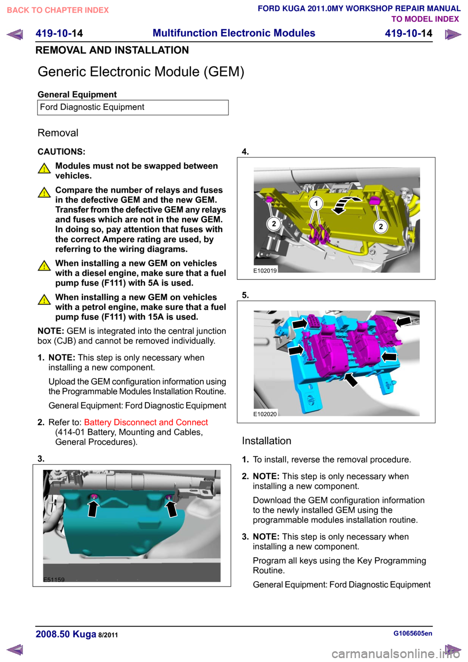
Generic Electronic Module (GEM)
General Equipment
Ford Diagnostic Equipment
Removal
CAUTIONS: Modules must not be swapped between
vehicles.
Compare the number of relays and fuses
in the defective GEM and the new GEM.
Transfer from the defective GEM any relays
and fuses which are not in the new GEM.
In doing so, pay attention that fuses with
the correct Ampere rating are used, by
referring to the wiring diagrams.
When installing a new GEM on vehicles
with a diesel engine, make sure that a fuel
pump fuse (F111) with 5A is used.
When installing a new GEM on vehicles
with a petrol engine, make sure that a fuel
pump fuse (F111) with 15A is used.
NOTE: GEM is integrated into the central junction
box (CJB) and cannot be removed individually.
1. NOTE: This step is only necessary when
installing a new component.
Upload the GEM configuration information using
the Programmable Modules Installation Routine.
General Equipment: Ford Diagnostic Equipment
2. Refer to: Battery Disconnect and Connect
(414-01 Battery, Mounting and Cables,
General Procedures).
3. 4.
5.
Installation
1.
To install, reverse the removal procedure.
2. NOTE: This step is only necessary when
installing a new component.
Download the GEM configuration information
to the newly installed GEM using the
programmable modules installation routine.
3. NOTE: This step is only necessary when
installing a new component.
Program all keys using the Key Programming
Routine.
General Equipment: Ford Diagnostic Equipment G1065605en
2008.50 Kuga 8/2011 419-10-14
Multifunction Electronic Modules
419-10-14
REMOVAL AND INSTALLATIONTO MODEL INDEX
BACK TO CHAPTER INDEX
FORD KUGA 2011.0MY WORKSHOP REPAIR MANUALE51159 122E102019 E102020
Page 1526 of 2057
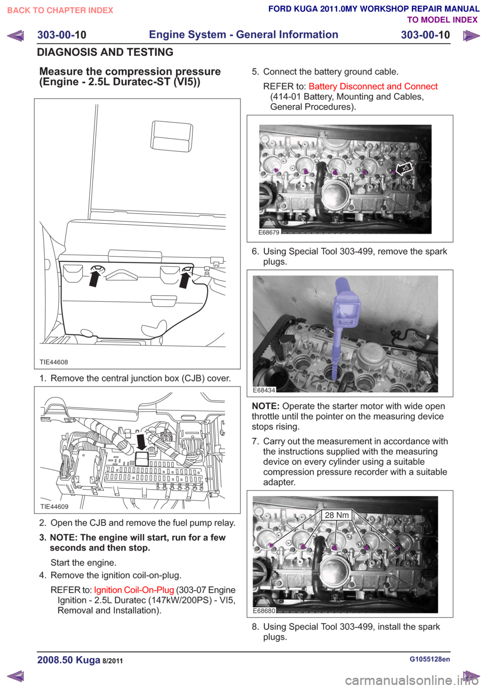
Measure the compression pressure
(Engine - 2.5L Duratec-ST (VI5))
TIE44608
1. Remove the central junction box (CJB) cover.
TIE44609
2. Open the CJB and remove the fuel pump relay.
3. NOTE: The engine will start, run for a fewseconds and then stop.
Start the engine.
4. Remove the ignition coil-on-plug.
REFER to: Ignition Coil-On-Plug (303-07 Engine
Ignition - 2.5L Duratec (147kW/200PS) - VI5,
Removal and Installation). 5. Connect the battery ground cable.
REFER to: Battery Disconnect and Connect
(414-01 Battery, Mounting and Cables,
General Procedures).
E68679
x5
6. Using Special Tool 303-499, remove the spark plugs.
E68434
NOTE: Operate the starter motor with wide open
throttle until the pointer on the measuring device
stops rising.
7. Carry out the measurement in accordance with the instructions supplied with the measuring
device on every cylinder using a suitable
compression pressure recorder with a suitable
adapter.
E68680
28 Nm
8. Using Special Tool 303-499, install the sparkplugs.
G1055128en2008.50 Kuga8/2011
303-00- 10
Engine System - General Information
303-00- 10
DIAGNOSIS AND TESTING
TO MODEL INDEX
BACK TO CHAPTER INDEX
FORD KUGA 2011.0MY WORKSHOP REPAIR MANUAL
Page 1753 of 2057
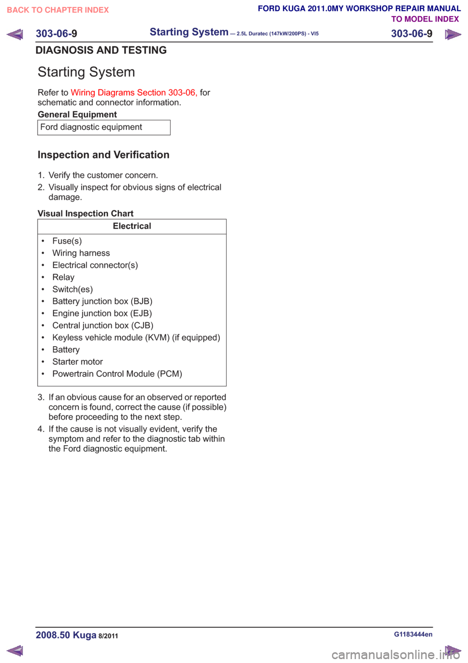
Starting System
Refer toWiring Diagrams Section 303-06, for
schematic and connector information.
General Equipment
Ford diagnostic equipment
Inspection and Verification
1. Verify the customer concern.
2. Visually inspect for obvious signs of electrical damage.
Visual Inspection Chart
Electrical
• Fuse(s)
• Wiring harness
• Electrical connector(s)
• Relay
• Switch(es)
• Battery junction box (BJB)
• Engine junction box (EJB)
• Central junction box (CJB)
• Keyless vehicle module (KVM) (if equipped)
• Battery
• Starter motor
• Powertrain Control Module (PCM)
3. If an obvious cause for an observed or reported concern is found, correct the cause (if possible)
before proceeding to the next step.
4. If the cause is not visually evident, verify the symptom and refer to the diagnostictab within
the Ford diagnostic equipment .
G1183444en2008.50 Kuga8/2011
303-06-9
Starting System— 2.5L Duratec (147kW/200PS) - VI5303-06-
9
DIAGNOSIS AND TESTING
TO MODEL INDEX
BACK TO CHAPTER INDEX
FORD KUGA 2011.0MY WORKSHOP REPAIR MANUAL
Page 2010 of 2057
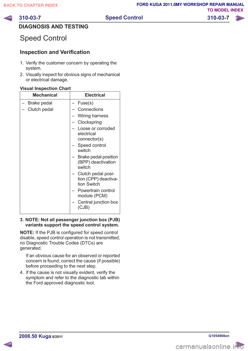
Speed Control
Inspection and Verification
1. Verify the customer concern by operating thesystem.
2. Visually inspect for obvious signs of mechanical or electrical damage.
Visual Inspection Chart
Electrical
Mechanical
– Fuse(s)
– Connections
– Wiring harness
– Clockspring
– Loose or corrodedelectrical
connector(s)
– Speed control switch
– Brake pedal position (BPP) deactivation
switch
– Clutch pedal posi- tion (CPP) deactiva-
tion Switch
– Powertrain control module (PCM)
– Central junction box (CJB)
– Brake pedal
– Clutch pedal
3. NOTE: Not all passenger junction box (PJB) variants support the speed control system.
NOTE: If the PJB is configured for speed control
disable, speed control operation is not transmitted,
no Diagnostic Trouble Codes (DTCs) are
generated.
If an obvious cause for an observed or reported
concern is found, correct the cause (if possible)
before proceeding to the next step.
4. If the cause is not visually evident, verify the symptom and refer to the diagnostic tab within
the Ford approved diagnostic tool.
G1054908en2008.50 Kuga8/2011
310-03- 7
Speed Control
310-03- 7
DIAGNOSIS AND TESTING
TO MODEL INDEX
BACK TO CHAPTER INDEX
FORD KUGA 2011.0MY WORKSHOP REPAIR MANUAL
Page 2015 of 2057
• The refrigerant line between the fixed orificetube and the evaporator must be cold from the
point where the fixed orifice tube is installed.
Depending on the weather, the refrigerant line
may also have ice on its surface.
• The refrigerant line between the evaporator and the A/C compressor including the dehydrator
must be cold.
Evaporator outlet line temperature test
To test the power of the A/C system, the
temperature at the evaporator outlet line must be
measured. To do this, the following preconditions
must be met:
• Open all windows.
• Set the air distribution to the defrost/dashboardposition and open all the ventilation nozzles.
• DO NOT switch on recirculated air.
• Select lowest blower switch setting.
• Select lowest temperature setting.
NOTE: The temperature measurement cannot be
done with a thermometer which makes no contact.
The surface reflection from the metal line may
cause incorrect readings.
Connect the temperature sensor (Fluke 80 PK-8)
to the outlet line of the evaporator. Locate the
temperature sensor as close as possible to the
evaporator. Connect the temperature sensor to the
multimeter.
Start the engine and allow it to run at idle speed
for several minutes.
Switch on the A/C.
After three minutes, measure the surface
temperature of the evaporator outlet line.
If the temperature measured is 4° C or lower, the
A/C system is OK. If the temperature is higher, the
A/C system may be under-filled. For further
information, refer to
REFER to: Air Conditioning (A/C) System
Recovery, Evacuation and Charging (412-00
Climate Control System - General Information,
General Procedures).
Frequent faults and their causes
If the cooling power of the A/C system is not
adequate, make certain that the temperature
control flap(s) is/are operating correctly. • No or poor cooling performance:
– Blockage or narrowing of a refrigerant line orin the dehydrator. The location of the
blockage or narrowing can easily be located
by temperature comparisons at the
refrigerant lines and the dehydrator. The
blockage or restriction is located at the point
where the temperature difference is
identified. Note: A temperature difference
in the area of the fixed orifice tube is
normal. If the location of the blockage or
narrowing is found, check the corresponding
component and renew as applicable.
• Sudden drop in cooling performance (after the air conditioning has been switched off for
approx. 5 minutes, the cooling performance
returns to normal):
– The cause is an iced-up fixed orifice tubebecause of moisture in the refrigerant circuit.
In order to ensure that moisture is completely
removed from the refrigerant circuit, the
dehydrator should be renewed and the
evacuation time should be extended to 2-3
hours. For further information
REFER to: Air Conditioning (A/C) System
Recovery, Evacuation and Charging
(412-00 Climate Control System - General
Information, General Procedures).
Sequence of A/C Request Signal
NOTE: The electronic automatic temperature
control (EATC) module is integrated into the air
conditioning control assembly.
NOTE: The generic electronic module (GEM) is
an integral part of the central junction box (CJB).
After actuating the A/C ON/OFF switch integrated
into the A/C control assembly, an A/C request
signal is sent from the A/C control assembly
(vehicles with EATC: EATC module) to the GEM.
From there, the signal is sent to the instrument
cluster via the MS-CAN bus. A gateway is installed
in the instrument cluster, which establishes the
connection between the MS-CAN bus and the
HS-CAN bus.
After the signal has been converted in the gateway,
it is relayed to the powertrain control module (PCM)
via the HS-CAN bus. Once all the required
parameters have been met, the PCM switches on
the refrigerant compressor and thus the A/C system
via the A/C clutch relay.
G1055878en2008.50 Kuga8/2011
412-00- 4
Climate Control System - General Information
412-00- 4
DIAGNOSIS AND TESTING
TO MODEL INDEX
BACK TO CHAPTER INDEX
FORD KUGA 2011.0MY WORKSHOP REPAIR MANUAL