Suction FORD KUGA 2011 1.G Workshop Manual
[x] Cancel search | Manufacturer: FORD, Model Year: 2011, Model line: KUGA, Model: FORD KUGA 2011 1.GPages: 2057
Page 123 of 2057
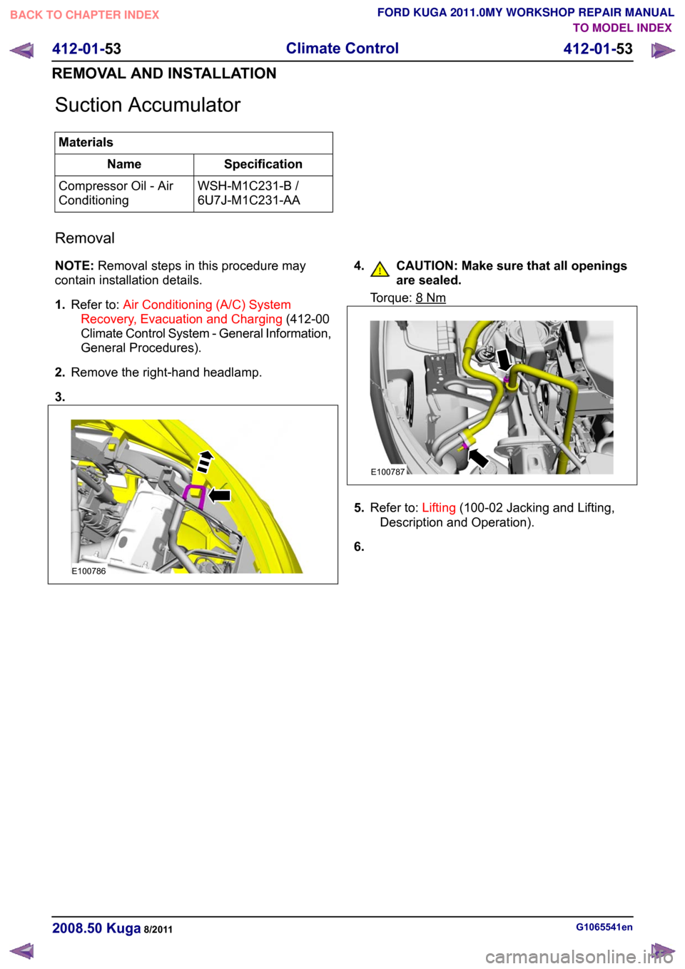
Suction Accumulator
Materials
Specification
Name
WSH-M1C231-B /
6U7J-M1C231-AA
Compressor Oil - Air
Conditioning
Removal
NOTE: Removal steps in this procedure may
contain installation details.
1. Refer to: Air Conditioning (A/C) System
Recovery, Evacuation and Charging (412-00
Climate Control System - General Information,
General Procedures).
2. Remove the right-hand headlamp.
3. 4. CAUTION: Make sure that all openings
are sealed. Torque: 8 Nm
5.
Refer to: Lifting(100-02 Jacking and Lifting,
Description and Operation).
6. G1065541en
2008.50 Kuga 8/2011 412-01-53
Climate Control
412-01-53
REMOVAL AND INSTALLATIONTO MODEL INDEX
BACK TO CHAPTER INDEX
FORD KUGA 2011.0MY WORKSHOP REPAIR MANUALE100786 E100787
Page 1466 of 2057
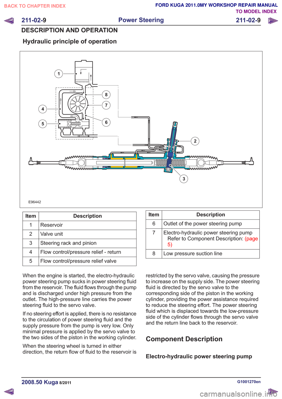
Hydraulic principle of operation
E96442
3
4
5
7
8
6
1
2
Description
Item
Reservoir
1
Valve unit
2
Steering rack and pinion
3
Flow control/pressure relief - return
4
Flow control/pressure relief valve
5Description
Item
Outlet of the power steering pump
6
Electro-hydraulic power steering pumpRefertoComponentDescription:(page
5)
7
Low pressure suction line
8
When the engine is started, the electro-hydraulic
power steering pump sucks in power steering fluid
from the reservoir. The fluid flows through the pump
and is discharged under high pressure from the
outlet. The high-pressure line carries the power
steering fluid to the servo valve.
If no steering effort is applied, there is no resistance
to the circulation of power steering fluid and the
supply pressure from the pump is very low. Only
minimal pressure is applied by the servo valve to
the two sides of the piston in the working cylinder.
When the steering wheel is turned in either
direction, the return flow of fluid to the reservoir is restricted by the servo valve, causing the pressure
to increase on the supply side. The power steering
fluid is directed by the servo valve to the
corresponding side of the piston in the working
cylinder, providing the power assistance required
to reduce the steering effort. The power steering
fluid which is displaced towards the low-pressure
side of the cylinder flows through the servo valve
and the return line back to the reservoir.
Component Description
Electro-hydraulic power steering pump
G1001270en2008.50 Kuga8/2011
211-02-
9
Power Steering
211-02- 9
DESCRIPTION AND OPERATION
TO MODEL INDEX
BACK TO CHAPTER INDEX
FORD KUGA 2011.0MY WORKSHOP REPAIR MANUAL
Page 1984 of 2057
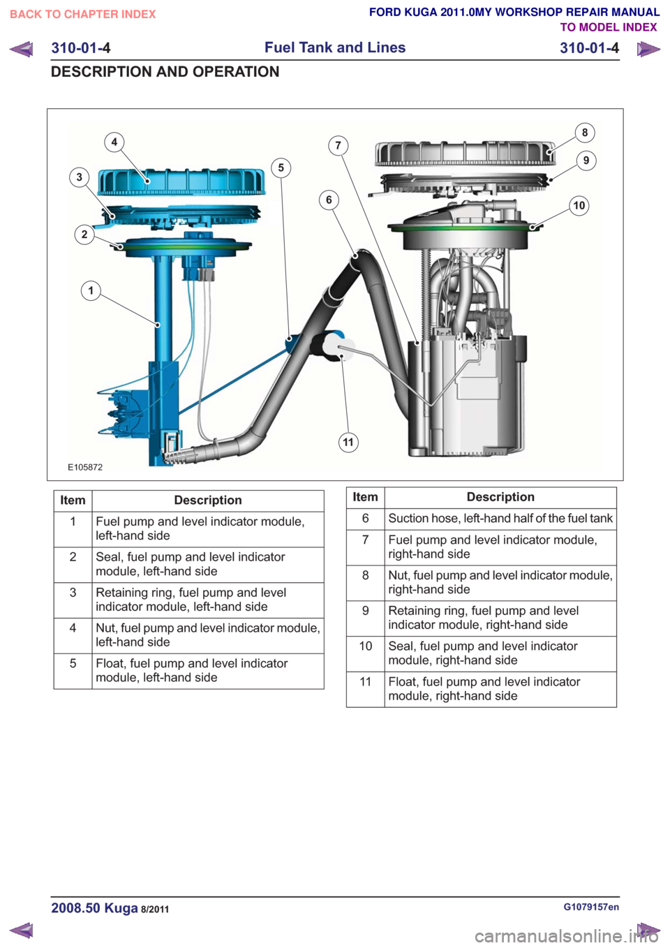
E105872
1
2
4
5
6
7
10
8
11
3
9
Description
Item
Fuel pump and level indicator module,
left-hand side
1
Seal, fuel pump and level indicator
module, left-hand side
2
Retaining ring, fuel pump and level
indicator module, left-hand side
3
Nut, fuel pump and level indicator module,
left-hand side
4
Float, fuel pump and level indicator
module, left-hand side
5Description
Item
Suction hose, left-hand half of the fuel tank
6
Fuel pump and level indicator module,
right-hand side
7
Nut, fuel pump and level indicator module,
right-hand side
8
Retaining ring, fuel pump and level
indicator module, right-hand side
9
Seal, fuel pump and level indicator
module, right-hand side
10
Float, fuel pump and level indicator
module, right-hand side
11
G1079157en2008.50 Kuga8/2011
310-01-
4
Fuel Tank and Lines
310-01- 4
DESCRIPTION AND OPERATION
TO MODEL INDEX
BACK TO CHAPTER INDEX
FORD KUGA 2011.0MY WORKSHOP REPAIR MANUAL
Page 1986 of 2057
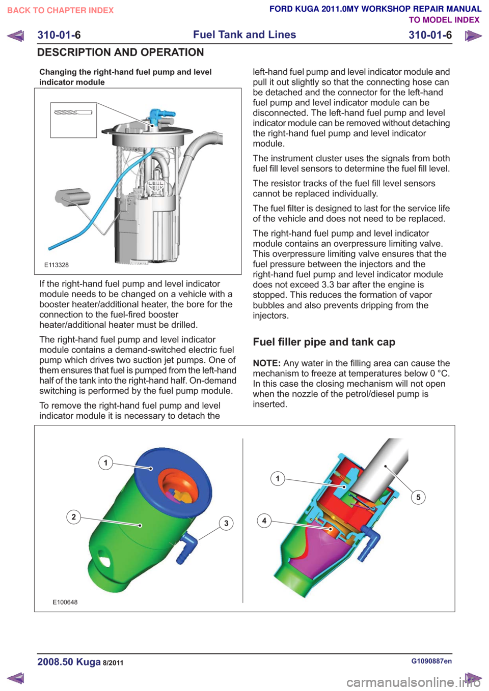
Changing the right-hand fuel pump and level
indicator module
E113328
If the right-hand fuel pump and level indicator
module needs to be changed on a vehicle with a
booster heater/additional heater, the bore for the
connection to the fuel-fired booster
heater/additional heater must be drilled.
The right-hand fuel pump and level indicator
module contains a demand-switched electric fuel
pump which drives two suction jet pumps. One of
them ensures that fuel is pumped from the left-hand
half of the tank into the right-hand half. On-demand
switching is performed by the fuel pump module.
To remove the right-hand fuel pump and level
indicator module it is necessary to detach theleft-hand fuel pump and level indicator module and
pull it out slightly so that the connecting hose can
be detached and the connector for the left-hand
fuel pump and level indicator module can be
disconnected. The left-hand fuel pump and level
indicator module can be removed without detaching
the right-hand fuel pump and level indicator
module.
The instrument cluster uses the signals from both
fuel fill level sensors to determine the fuel fill level.
The resistor tracks of the fuel fill level sensors
cannot be replaced individually.
The fuel filter is designed to last for the service life
of the vehicle and does not need to be replaced.
The right-hand fuel pump and level indicator
module contains an overpressure limiting valve.
This overpressure limiting valve ensures that the
fuel pressure between the injectors and the
right-hand fuel pump and level indicator module
does not exceed 3.3 bar after the engine is
stopped. This reduces the formation of vapor
bubbles and also prevents dripping from the
injectors.
Fuel filler pipe and tank cap
NOTE:
Any water in the filling area can cause the
mechanism to freeze at temperatures below 0 °C.
In this case the closing mechanism will not open
when the nozzle of the petrol/diesel pump is
inserted.
43
1
2
1
5
43
1
2
1
5
E100648
G1090887en2008.50 Kuga8/2011
310-01- 6
Fuel Tank and Lines
310-01- 6
DESCRIPTION AND OPERATION
TO MODEL INDEX
BACK TO CHAPTER INDEX
FORD KUGA 2011.0MY WORKSHOP REPAIR MANUAL
Page 2025 of 2057
Electronic Leak Detection
1.Refer to: Air Conditioning (A/C) System Health
and Safety Precautions (100-00 General
Information, Description and Operation).
2. WARNINGS:
Before starting leak detection, make
sure that the area where it is to be done
is well ventilated. If the surrounding air
is contaminated with refrigerant gas, the
leak detector will indicate this gas all
the time. Odors from other chemicals
such as antifreeze, diesel fuel, disc
brake cleaner, or other cleaning
solvents can cause the same problem.
Prevent air movement while performing
leak detection.
The refrigerant identification equipment
must be used before attaching the
manifold gauge set. Otherwise the
manifold gauge set may become
contaminated. Contaminated refrigerant
must be disposed of as special waste.
Follow the manufacturer's instructions
when working with the service unit.
NOTE: At 24°C with the engine switched off,
both manifold gauges should show 4.1 to 5.5
bar.
Attach the manifold gauge set to the service
gauge port valves.
3. For the leak test, close the manual valves on
the gauge set.
4. If little or no pressure is indicated, charge the
system with approx. 300g of refrigerant. Refer
to: Air Conditioning System - Evacuate and
Refill.
5. Use the R-134a Automatic Calibration Halogen
Leak Detector to leak test the refrigerant system.
Follow the instructions included with leak
detector for handling and operation techniques.
6. If any leak is found, extract the refrigerant under
suction. Refer to: Air Conditioning System -
Evacuate and Refill.
G549836en2008.50 Kuga8/2011
412-00- 14
Climate Control System - General Information
412-00- 14
GENERAL PROCEDURES
TO MODEL INDEX
BACK TO CHAPTER INDEX
FORD KUGA 2011.0MY WORKSHOP REPAIR MANUAL
Page 2029 of 2057

412-01-42
Heater Core and Evaporator Core Housing .......................................................................
412-01-45
(34 364 0)
Heater Core — RHD ........................................................................\
...............
412-01-53
Suction Accumulator ........................................................................\
...................................
412-01-56
Suction Accumulator to Air Conditioning (A/C) Compressor Line ......................................
412-01-57
Suction Accumulator to Air Conditioning (A/C) Compressor Line — 2.5L Duratec
(147kW/200PS) - VI5 ........................................................................\
................................
412-01-58
Low-Pressure Cutoff Switch ........................................................................\
.......................
412-01-59
High-Pressure Cutoff Switch ........................................................................\
.......................
412-01-60
Evaporator ........................................................................\
..................................................
412-01-62
Evaporator Outlet Line ........................................................................\
................................
412-01-65
Evaporator Core Orifice ........................................................................\
..............................
412-01-68
Condenser to Evaporator Line........................................................................\
....................
412-01-71
(34 300 0)
Climate Control Assembly — Vehicles With: Manual Temperature Control ....
412-01-72
(34 300 0)
Climate Control Assembly — Vehicles With: Automatic Temperature Control .
412-01-73
(34 485 4)
Footwell Air Discharge Temperature Sensor ..................................................
412-01-74
Center Register Air Discharge Temperature Sensor ..........................................................
412-01-75
In-Vehicle Temperature Sensor ........................................................................\
..................
412-01-76
(34 676 0)
Ambient Air Temperature Sensor ...................................................................
412-01-77
(34 665 0)
Sunload Sensor ........................................................................\
......................
412-01-78
(34 591 0)
Footwell Vent/Duct Blend Door Actuator — RHD ...........................................
412-01-79
(34 606 0)
Air Inlet Blend Door Actuator ........................................................................\
..
412-01-80
(34 608 0)
Driver Side Temperature Blend Door Actuator ...............................................
412-01-81
(34 608 0)
Passenger Side Temperature Blend Door Actuator .......................................
412-01-82
(34 591 0)
Defrost Vent/Register Blend Door Actuator — RHD ......................................
412-01-2
Climate Control
412-01- 2
.
TO MODEL INDEX
BACK TO CHAPTER INDEX
PAGE 2 OF 2 FORD KUGA 2011.0MY WORKSHOP REPAIR MANUAL
Page 2050 of 2057
1
2
3
5
4
67
8
9
10
11
E100819
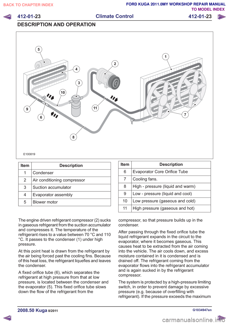
Description
Item
Condenser
1
Air conditioning compressor
2
Suction accumulator
3
Evaporator assembly
4
Blower motor
5Description
Item
Evaporator Core Orifice Tube
6
Cooling fans.
7
High - pressure (liquid and warm)
8
Low - pressure (liquid and cool)
9
Low pressure (gaseous and cold)
10
High pressure (gaseous and hot)
11
The engine driven refrigerant compressor (2) sucks
in gaseous refrigerant from the suction accumulator
and compresses it. The temperature of the
refrigerant rises to a value between 70 °C and 110
°C. It passes to the condenser (1) under high
pressure.
At this point heat is drawn from the refrigerant by
the air being forced past the cooling fins. Because
of this heat loss, the refrigerant liquefies and leaves
the condenser.
A fixed orifice tube (6), which separates the
refrigerant at high pressure from that at low
pressure, is located between the condenser and
the evaporator (5). This fixed orifice tube slows
down the flow of the refrigerant from the compressor, so that pressure builds up in the
condenser.
After passing through the fixed orifice tube the
liquid refrigerant expands in the circuit to the
evaporator, where it becomes gaseous. This
causes heat to be extracted from the air coming
into the vehicle. The air cools down, and excess
moisture contained in it is condensed and is
drained off. The refrigerant coming from the
evaporator flows into the refrigerant accumulator
and is again sucked in by the refrigerant
compressor.
The system is protected by a high-pressure limiting
switch, in order to prevent damage by excessive
pressure (e.g. because of overfilling with
refrigerant). If the pressure exceeds the maximum
G1034947en2008.50 Kuga8/2011
412-01-
23
Climate Control
412-01- 23
DESCRIPTION AND OPERATION
TO MODEL INDEX
BACK TO CHAPTER INDEX
FORD KUGA 2011.0MY WORKSHOP REPAIR MANUAL