set clock FORD KUGA 2011 1.G Workshop Manual
[x] Cancel search | Manufacturer: FORD, Model Year: 2011, Model line: KUGA, Model: FORD KUGA 2011 1.GPages: 2057
Page 1170 of 2057
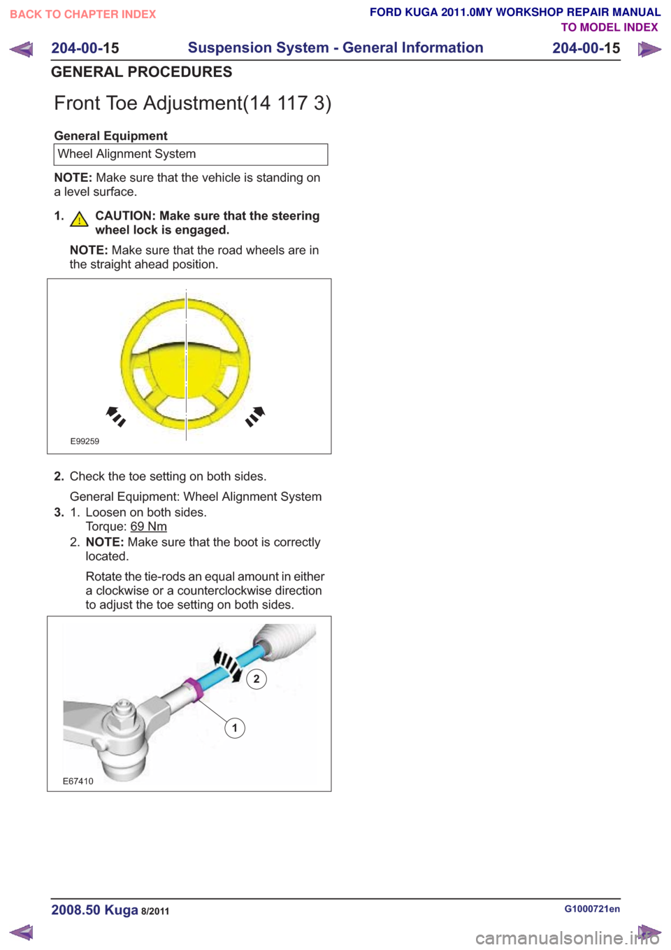
Front Toe Adjustment(14 117 3)
General EquipmentWheel Alignment System
NOTE: Make sure that the vehicle is standing on
a level surface.
1. CAUTION: Make sure that the steering wheel lock is engaged.
NOTE: Make sure that the road wheels are in
the straight ahead position.
E99259
2. Check the toe setting on both sides.
General Equipment: Wheel Alignment System
3. Loosen on both sides.
Torque: 69
Nm
1.
2.NOTE: Make sure that the boot is correctly
located.
Rotate the tie-rods an equal amount in either
a clockwise or a counterclockwise direction
to adjust the toe setting on both sides.
2
E67410
1
2
G1000721en2008.50 Kuga8/2011
204-00- 15
Suspension System - General Information
204-00- 15
GENERAL PROCEDURES
TO MODEL INDEX
BACK TO CHAPTER INDEX
FORD KUGA 2011.0MY WORKSHOP REPAIR MANUAL
Page 1546 of 2057
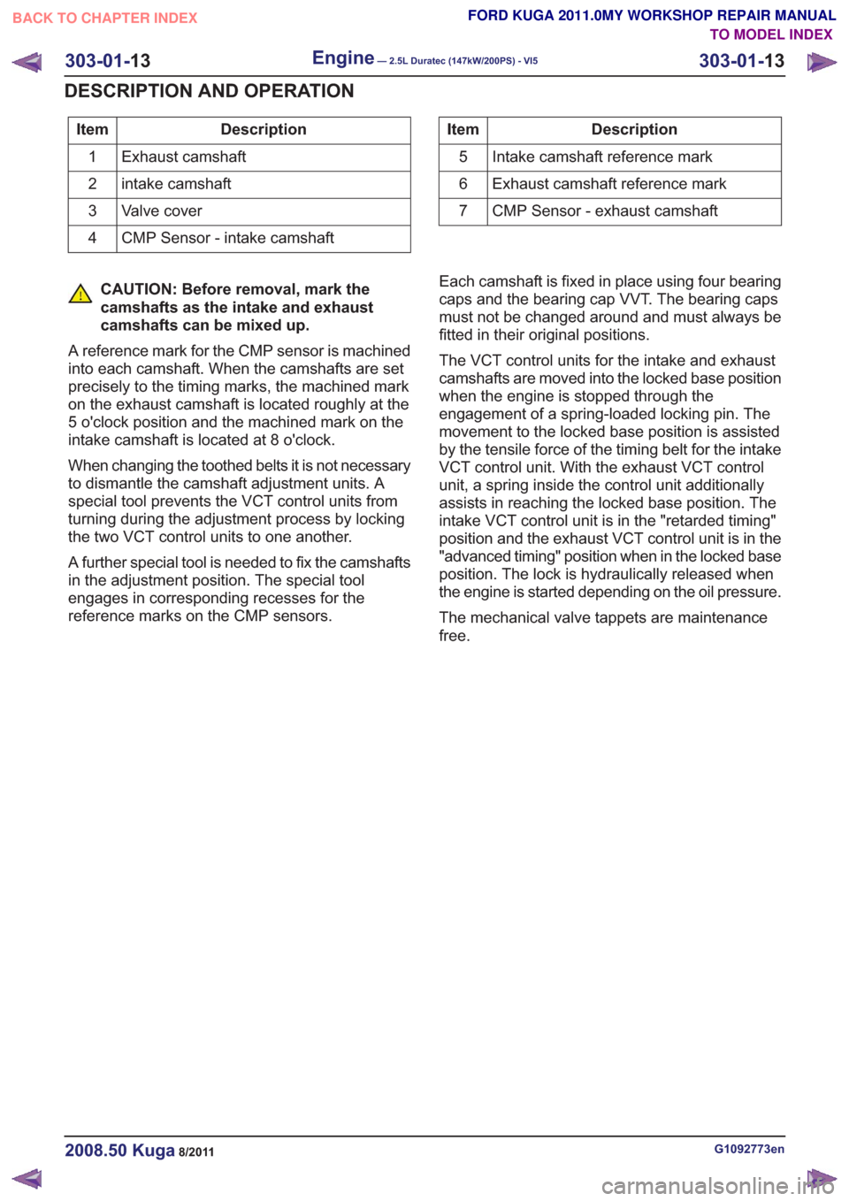
Description
Item
Exhaust camshaft
1
intake camshaft
2
Valve cover
3
CMP Sensor - intake camshaft
4Description
Item
Intake camshaft reference mark
5
Exhaust camshaft reference mark
6
CMP Sensor - exhaust camshaft
7
CAUTION: Before removal, mark the
camshafts as the intake and exhaust
camshafts can be mixed up.
A reference mark for the CMP sensor is machined
into each camshaft. When the camshafts are set
precisely to the timing marks, the machined mark
on the exhaust camshaft is located roughly at the
5 o'clock position and the machined mark on the
intake camshaft is located at 8 o'clock.
When changing the toothed belts it is not necessary
to dismantle the camshaft adjustment units. A
special tool prevents the VCT control units from
turning during the adjustment process by locking
the two VCT control units to one another.
A further special tool is needed to fix the camshafts
in the adjustment position. The special tool
engages in corresponding recesses for the
reference marks on the CMP sensors. Each camshaft is fixed in place using four bearing
caps and the bearing cap VVT. The bearing caps
must not be changed around and must always be
fitted in their original positions.
The VCT control units for the intake and exhaust
camshafts are moved into the locked base position
when the engine is stopped through the
engagement of a spring-loaded locking pin. The
movement to the locked base position is assisted
by the tensile force of the timing belt for the intake
VCT control unit. With the exhaust VCT control
unit, a spring inside the control unit additionally
assists in reaching the locked base position. The
intake VCT control unit is in the "retarded timing"
position and the exhaust VCT control unit is in the
"advanced timing" position when in the locked base
position. The lock is hydraulically released when
the engine is started depending on the oil pressure.
The mechanical valve tappets are maintenance
free.
G1092773en2008.50 Kuga8/2011
303-01-
13
Engine— 2.5L Duratec (147kW/200PS) - VI5303-01-
13
DESCRIPTION AND OPERATION
TO MODEL INDEX
BACK TO CHAPTER INDEX
FORD KUGA 2011.0MY WORKSHOP REPAIR MANUAL
Page 1855 of 2057
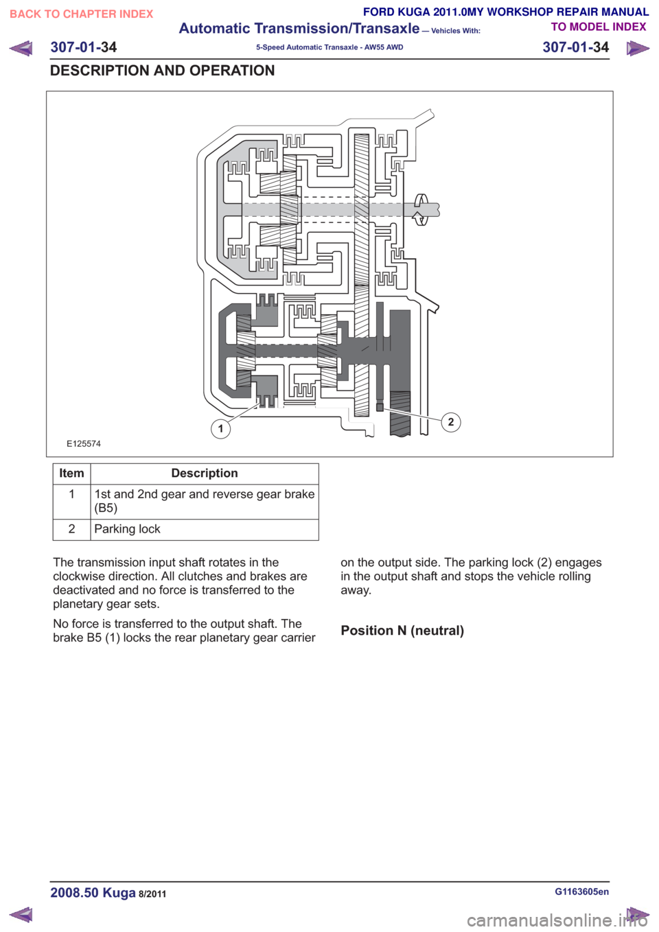
E125574
12
Description
Item
1st and 2nd gear and reverse gear brake
(B5)
1
Parking lock
2
The transmission input shaft rotates in the
clockwise direction. All clutches and brakes are
deactivated and no force is transferred to the
planetary gear sets.
No force is transferred to the output shaft. The
brake B5 (1) locks the rear planetary gear carrier on the output side. The parking lock (2) engages
in the output shaft and stops the vehicle rolling
away.
Position N (neutral)
G1163605en2008.50 Kuga8/2011
307-01-
34
Automatic Transmission/Transaxle
— Vehicles With:
5-Speed Automatic Transaxle - AW55 AWD
307-01- 34
DESCRIPTION AND OPERATION
TO MODEL INDEX
BACK TO CHAPTER INDEX
FORD KUGA 2011.0MY WORKSHOP REPAIR MANUAL
Page 1856 of 2057
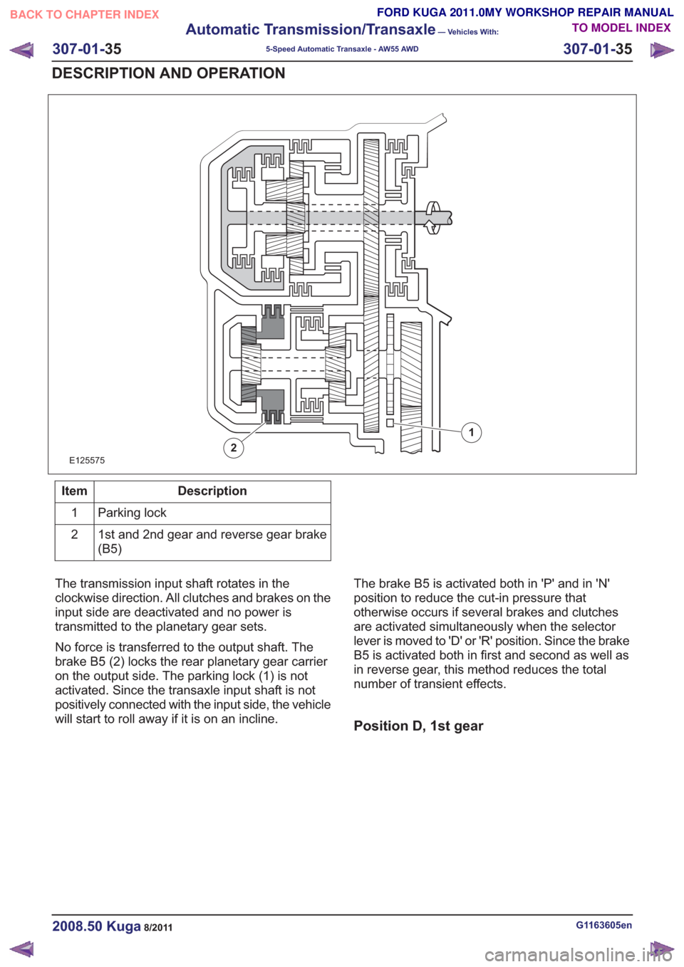
E125575
1
2
Description
Item
Parking lock
1
1st and 2nd gear and reverse gear brake
(B5)
2
The transmission input shaft rotates in the
clockwise direction. All clutches and brakes on the
input side are deactivated and no power is
transmitted to the planetary gear sets.
No force is transferred to the output shaft. The
brake B5 (2) locks the rear planetary gear carrier
on the output side. The parking lock (1) is not
activated. Since the transaxle input shaft is not
positively connected with the input side, the vehicle
will start to roll away if it is on an incline. The brake B5 is activated both in 'P' and in 'N'
position to reduce the cut-in pressure that
otherwise occurs if several brakes and clutches
are activated simultaneously when the selector
lever is moved to 'D' or 'R' position. Since the brake
B5 is activated both in first and second as well as
in reverse gear, this method reduces the total
number of transient effects.
Position D, 1st gear
G1163605en2008.50 Kuga8/2011
307-01-
35
Automatic Transmission/Transaxle
— Vehicles With:
5-Speed Automatic Transaxle - AW55 AWD
307-01- 35
DESCRIPTION AND OPERATION
TO MODEL INDEX
BACK TO CHAPTER INDEX
FORD KUGA 2011.0MY WORKSHOP REPAIR MANUAL
Page 1857 of 2057
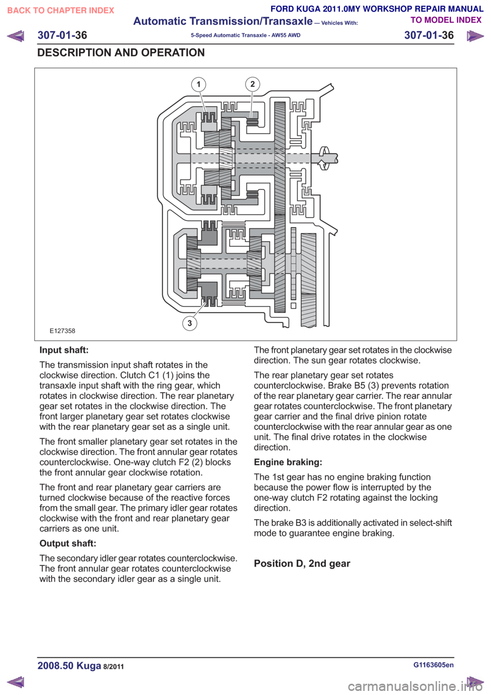
E127358
21
3
Input shaft:
The transmission input shaft rotates in the
clockwise direction. Clutch C1 (1) joins the
transaxle input shaft with the ring gear, which
rotates in clockwise direction. The rear planetary
gear set rotates in the clockwise direction. The
front larger planetary gear set rotates clockwise
with the rear planetary gear set as a single unit.
The front smaller planetary gear set rotates in the
clockwise direction. The front annular gear rotates
counterclockwise. One-way clutch F2 (2) blocks
the front annular gear clockwise rotation.
The front and rear planetary gear carriers are
turned clockwise because of the reactive forces
from the small gear. The primary idler gear rotates
clockwise with the front and rear planetary gear
carriers as one unit.
Output shaft:
The secondary idler gear rotates counterclockwise.
The front annular gear rotates counterclockwise
with the secondary idler gear as a single unit.The front planetary gear set rotates in the clockwise
direction. The sun gear rotates clockwise.
The rear planetary gear set rotates
counterclockwise. Brake B5 (3) prevents rotation
of the rear planetary gear carrier. The rear annular
gear rotates counterclockwise. The front planetary
gear carrier and the final drive pinion rotate
counterclockwise with the rear annular gear as one
unit. The final drive rotates in the clockwise
direction.
Engine braking:
The 1st gear has no engine braking function
because the power flow is interrupted by the
one-way clutch F2 rotating against the locking
direction.
The brake B3 is additionally activated in select-shift
mode to guarantee engine braking.
Position D, 2nd gear
G1163605en2008.50 Kuga8/2011
307-01-
36
Automatic Transmission/Transaxle
— Vehicles With:
5-Speed Automatic Transaxle - AW55 AWD
307-01- 36
DESCRIPTION AND OPERATION
TO MODEL INDEX
BACK TO CHAPTER INDEX
FORD KUGA 2011.0MY WORKSHOP REPAIR MANUAL
Page 1858 of 2057
E127359
1
2
3
4
5
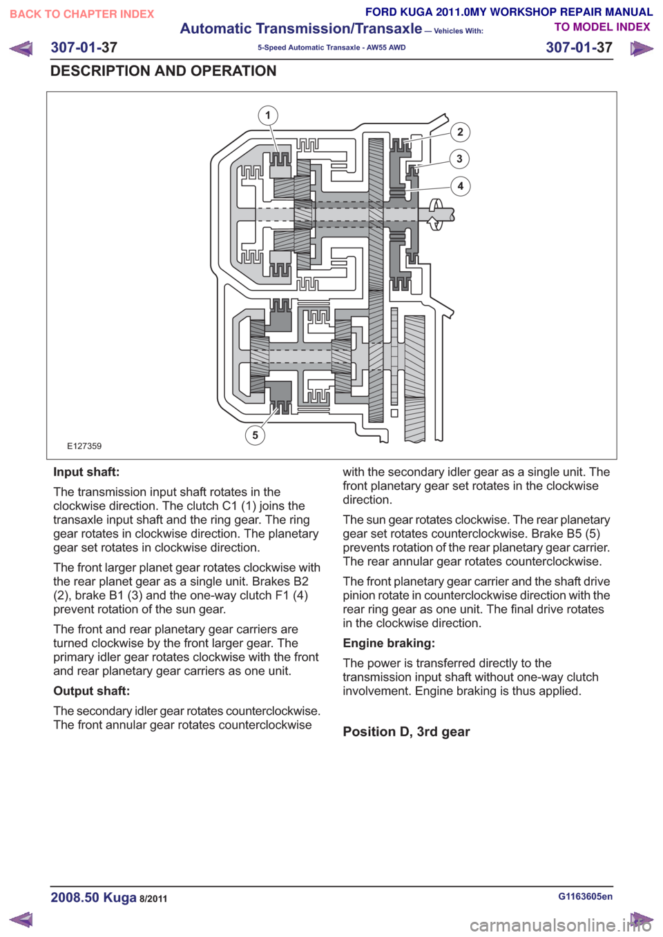
Input shaft:
The transmission input shaft rotates in the
clockwise direction. The clutch C1 (1) joins the
transaxle input shaft and the ring gear. The ring
gear rotates in clockwise direction. The planetary
gear set rotates in clockwise direction.
The front larger planet gear rotates clockwise with
the rear planet gear as a single unit. Brakes B2
(2), brake B1 (3) and the one-way clutch F1 (4)
prevent rotation of the sun gear.
The front and rear planetary gear carriers are
turned clockwise by the front larger gear. The
primary idler gear rotates clockwise with the front
and rear planetary gear carriers as one unit.
Output shaft:
The secondary idler gear rotates counterclockwise.
The front annular gear rotates counterclockwisewith the secondary idler gear as a single unit. The
front planetary gear set rotates in the clockwise
direction.
The sun gear rotates clockwise. The rear planetary
gear set rotates counterclockwise. Brake B5 (5)
prevents rotation of the rear planetary gear carrier.
The rear annular gear rotates counterclockwise.
The front planetary gear carrier and the shaft drive
pinion rotate in counterclockwise direction with the
rear ring gear as one unit. The final drive rotates
in the clockwise direction.
Engine braking:
The power is transferred directly to the
transmission input shaft without one-way clutch
involvement. Engine braking is thus applied.
Position D, 3rd gear
G1163605en2008.50 Kuga8/2011
307-01-
37
Automatic Transmission/Transaxle
— Vehicles With:
5-Speed Automatic Transaxle - AW55 AWD
307-01- 37
DESCRIPTION AND OPERATION
TO MODEL INDEX
BACK TO CHAPTER INDEX
FORD KUGA 2011.0MY WORKSHOP REPAIR MANUAL
Page 1859 of 2057
E127360
1
2
3
4
5
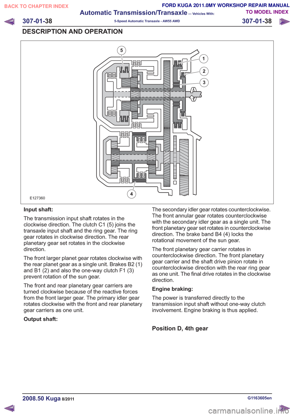
Input shaft:
The transmission input shaft rotates in the
clockwise direction. The clutch C1 (5) joins the
transaxle input shaft and the ring gear. The ring
gear rotates in clockwise direction. The rear
planetary gear set rotates in the clockwise
direction.
The front larger planet gear rotates clockwise with
the rear planet gear as a single unit. Brakes B2 (1)
and B1 (2) and also the one-way clutch F1 (3)
prevent rotation of the sun gear.
The front and rear planetary gear carriers are
turned clockwise because of the reactive forces
from the front larger gear. The primary idler gear
rotates clockwise with the front and rear planetary
gear carriers as one unit.
Output shaft:The secondary idler gear rotates counterclockwise.
The front annular gear rotates counterclockwise
with the secondary idler gear as a single unit. The
front planetary gear set rotates in counterclockwise
direction. The brake band B4 (4) locks the
rotational movement of the sun gear.
The front planetary gear carrier rotates in
counterclockwise direction. The front planetary
gear carrier and the shaft drive pinion rotate in
counterclockwise direction with the rear ring gear
as one unit. The final drive rotates in the clockwise
direction.
Engine braking:
The power is transferred directly to the
transmission input shaft without one-way clutch
involvement. Engine braking is thus applied.
Position D, 4th gear
G1163605en2008.50 Kuga8/2011
307-01-
38
Automatic Transmission/Transaxle
— Vehicles With:
5-Speed Automatic Transaxle - AW55 AWD
307-01- 38
DESCRIPTION AND OPERATION
TO MODEL INDEX
BACK TO CHAPTER INDEX
FORD KUGA 2011.0MY WORKSHOP REPAIR MANUAL
Page 1860 of 2057
E127361
1
2
3
4
5
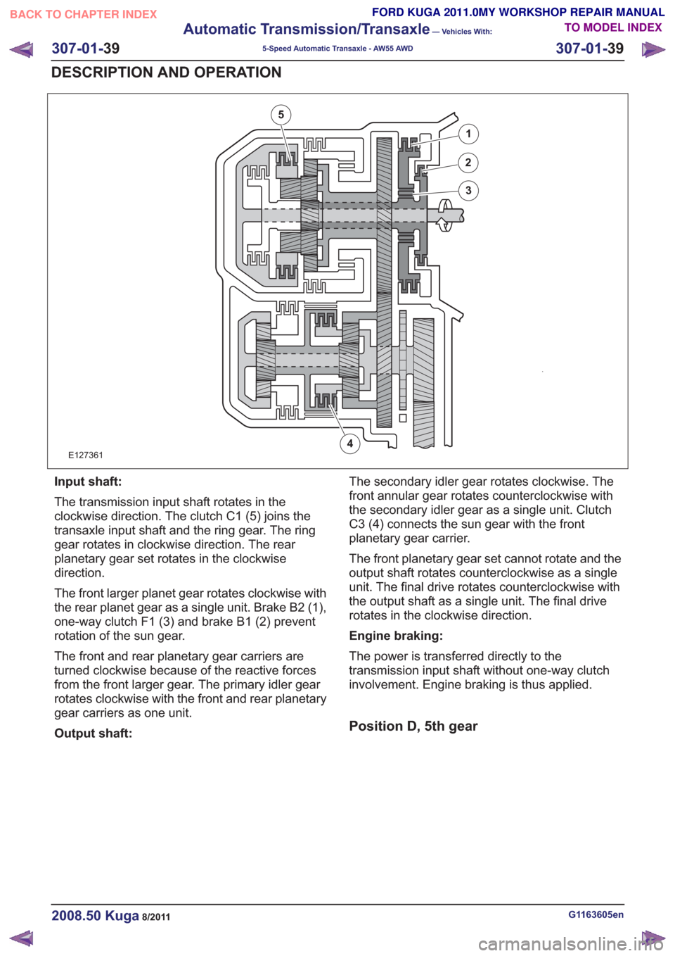
Input shaft:
The transmission input shaft rotates in the
clockwise direction. The clutch C1 (5) joins the
transaxle input shaft and the ring gear. The ring
gear rotates in clockwise direction. The rear
planetary gear set rotates in the clockwise
direction.
The front larger planet gear rotates clockwise with
the rear planet gear as a single unit. Brake B2 (1),
one-way clutch F1 (3) and brake B1 (2) prevent
rotation of the sun gear.
The front and rear planetary gear carriers are
turned clockwise because of the reactive forces
from the front larger gear. The primary idler gear
rotates clockwise with the front and rear planetary
gear carriers as one unit.
Output shaft:The secondary idler gear rotates clockwise. The
front annular gear rotates counterclockwise with
the secondary idler gear as a single unit. Clutch
C3 (4) connects the sun gear with the front
planetary gear carrier.
The front planetary gear set cannot rotate and the
output shaft rotates counterclockwise as a single
unit. The final drive rotates counterclockwise with
the output shaft as a single unit. The final drive
rotates in the clockwise direction.
Engine braking:
The power is transferred directly to the
transmission input shaft without one-way clutch
involvement. Engine braking is thus applied.
Position D, 5th gear
G1163605en2008.50 Kuga8/2011
307-01-
39
Automatic Transmission/Transaxle
— Vehicles With:
5-Speed Automatic Transaxle - AW55 AWD
307-01- 39
DESCRIPTION AND OPERATION
TO MODEL INDEX
BACK TO CHAPTER INDEX
FORD KUGA 2011.0MY WORKSHOP REPAIR MANUAL
Page 1861 of 2057
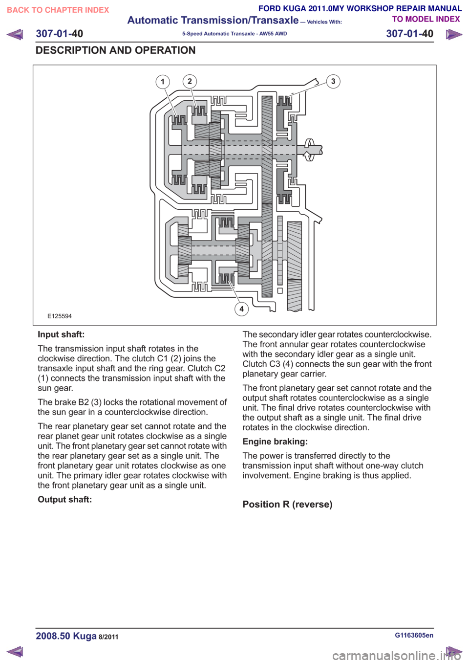
E125594
12
4
3
Input shaft:
The transmission input shaft rotates in the
clockwise direction. The clutch C1 (2) joins the
transaxle input shaft and the ring gear. Clutch C2
(1) connects the transmission input shaft with the
sun gear.
The brake B2 (3) locks the rotational movement of
the sun gear in a counterclockwise direction.
The rear planetary gear set cannot rotate and the
rear planet gear unit rotates clockwise as a single
unit. The front planetary gear set cannot rotate with
the rear planetary gear set as a single unit. The
front planetary gear unit rotates clockwise as one
unit. The primary idler gear rotates clockwise with
the front planetary gear unit as a single unit.
Output shaft:The secondary idler gear rotates counterclockwise.
The front annular gear rotates counterclockwise
with the secondary idler gear as a single unit.
Clutch C3 (4) connects the sun gear with the front
planetary gear carrier.
The front planetary gear set cannot rotate and the
output shaft rotates counterclockwise as a single
unit. The final drive rotates counterclockwise with
the output shaft as a single unit. The final drive
rotates in the clockwise direction.
Engine braking:
The power is transferred directly to the
transmission input shaft without one-way clutch
involvement. Engine braking is thus applied.
Position R (reverse)
G1163605en2008.50 Kuga8/2011
307-01-
40
Automatic Transmission/Transaxle
— Vehicles With:
5-Speed Automatic Transaxle - AW55 AWD
307-01- 40
DESCRIPTION AND OPERATION
TO MODEL INDEX
BACK TO CHAPTER INDEX
FORD KUGA 2011.0MY WORKSHOP REPAIR MANUAL
Page 1862 of 2057
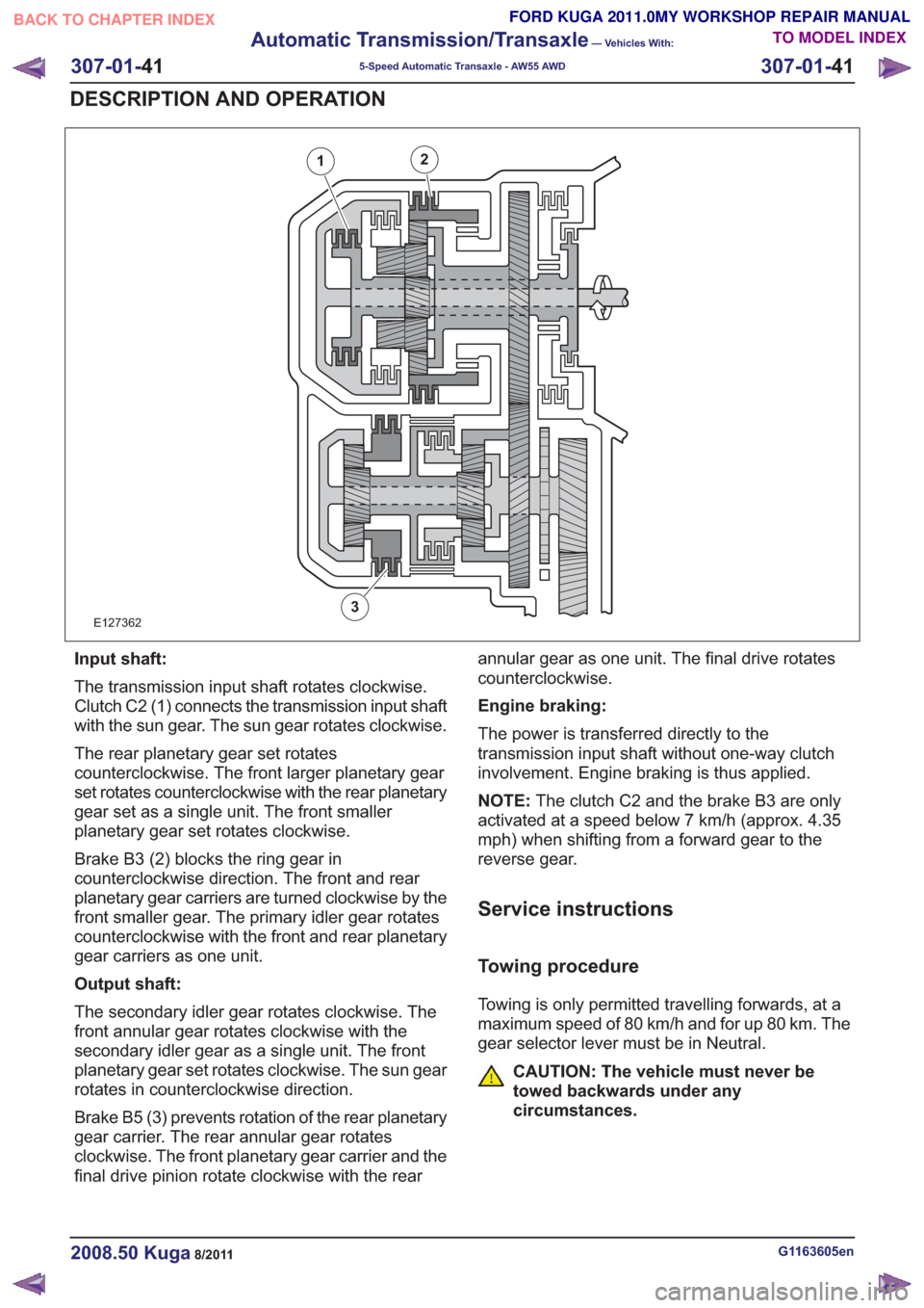
E127362
12
3
Input shaft:
The transmission input shaft rotates clockwise.
Clutch C2 (1) connects the transmission input shaft
with the sun gear. The sun gear rotates clockwise.
The rear planetary gear set rotates
counterclockwise. The front larger planetary gear
set rotates counterclockwise with the rear planetary
gear set as a single unit. The front smaller
planetary gear set rotates clockwise.
Brake B3 (2) blocks the ring gear in
counterclockwise direction. The front and rear
planetary gear carriers are turned clockwise by the
front smaller gear. The primary idler gear rotates
counterclockwise with the front and rear planetary
gear carriers as one unit.
Output shaft:
The secondary idler gear rotates clockwise. The
front annular gear rotates clockwise with the
secondary idler gear as a single unit. The front
planetary gear set rotates clockwise. The sun gear
rotates in counterclockwise direction.
Brake B5 (3) prevents rotation of the rear planetary
gear carrier. The rear annular gear rotates
clockwise. The front planetary gear carrier and the
final drive pinion rotate clockwise with the rearannular gear as one unit. The final drive rotates
counterclockwise.
Engine braking:
The power is transferred directly to the
transmission input shaft without one-way clutch
involvement. Engine braking is thus applied.
NOTE:
The clutch C2 and the brake B3 are only
activated at a speed below 7 km/h (approx. 4.35
mph) when shifting from a forward gear to the
reverse gear.
Service instructions
Towing procedure
Towing is only permitted travelling forwards, at a
maximum speed of 80 km/h and for up 80 km. The
gear selector lever must be in Neutral.
CAUTION: The vehicle must never be
towed backwards under any
circumstances.
G1163605en2008.50 Kuga8/2011
307-01- 41
Automatic Transmission/Transaxle
— Vehicles With:
5-Speed Automatic Transaxle - AW55 AWD
307-01- 41
DESCRIPTION AND OPERATION
TO MODEL INDEX
BACK TO CHAPTER INDEX
FORD KUGA 2011.0MY WORKSHOP REPAIR MANUAL