width FORD KUGA 2011 1.G Workshop Manual
[x] Cancel search | Manufacturer: FORD, Model Year: 2011, Model line: KUGA, Model: FORD KUGA 2011 1.GPages: 2057
Page 165 of 2057
System Operation
Electric Booster Heater
In diesel vehicles which give off little residual heat,
a booster heater is used to heat the passenger
compartment rapidly in the case of low ambient
temperatures.
If the interior temperature has been set to HI, or if
the heater controls have been switched to the
highest setting, the two-zone air conditioning
system sends an "electric booster heater ON"
request signal to the CAN (controller area network)
via the medium speed GEM bus. If a manual air
conditioning system is installed, the signal is
transmitted via a conventional cable connection.
The GEM switches on the electric booster heater
depending on the following parameters:
• Engine coolant temperature is below 60 °C.
• Ambient air temperature is below 10 °C.
• Sufficient generator capacity is available.
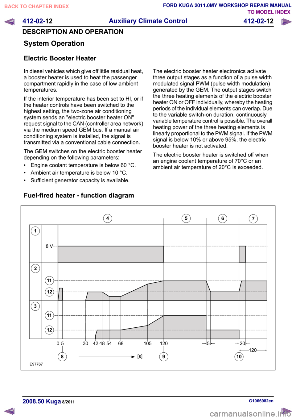
The electric booster heater electronics activate
three output stages as a function of a pulse width
modulated signal PWM (pulse width modulation)
generated by the GEM. The output stages switch
the three heating elements of the electric booster
heater ON or OFF individually, whereby the heating
periods of the individual elements can overlap. Due
to the variable switch-on duration, continuously
variable temperature control is possible. The overall
heating power of the three heating elements is
linearly proportional to the PWM signal. If the PWM
signal is below 10% or above 95%, the electric
booster heater is not activated.
The electric booster heater is switched off when
an engine coolant temperature of 70°C or an
ambient air temperature of 20°C is exceeded.
Fuel-fired heater - function diagram G1066982en
2008.50 Kuga 8/2011 412-02-12
Auxiliary Climate Control
412-02-12
DESCRIPTION AND OPERATIONTO MODEL INDEX
BACK TO CHAPTER INDEX
FORD KUGA 2011.0MY WORKSHOP REPAIR MANUAL12345671205304254481201056820108V58911121112E977670
Page 212 of 2057
Parking Aid Camera
For vehicles with a DVD navigation system with a
touch screen, the parking aid camera is supplied
as standard. For vehicles with a standard
navigation system, the camera can be ordered as
an optional extra. The system essentially consists
of a camera with a wide angle lens, a control unit
and a wiring harness which is not integrated in the
vehicle wiring harness.
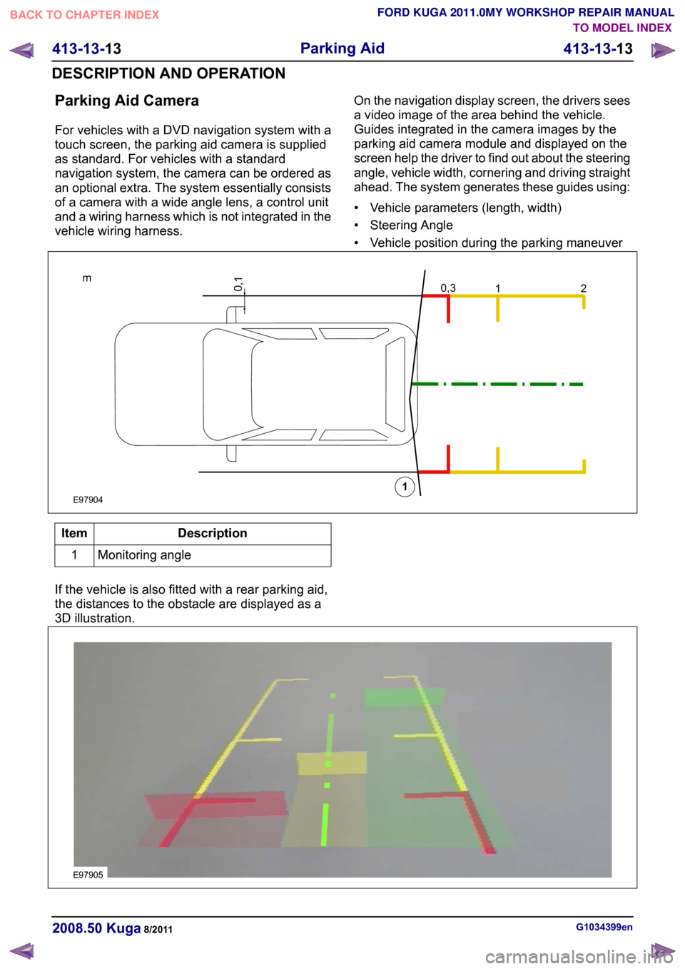
On the navigation display screen, the drivers sees
a video image of the area behind the vehicle.
Guides integrated in the camera images by the
parking aid camera module and displayed on the
screen help the driver to find out about the steering
angle, vehicle width, cornering and driving straight
ahead. The system generates these guides using:
• Vehicle parameters (length, width)
• Steering Angle
• Vehicle position during the parking maneuverDescription
Item
Monitoring angle
1
If the vehicle is also fitted with a rear parking aid,
the distances to the obstacle are displayed as a
3D illustration. G1034399en
2008.50 Kuga 8/2011 413-13-13
Parking Aid
413-13-13
DESCRIPTION AND OPERATIONTO MODEL INDEX
BACK TO CHAPTER INDEX
FORD KUGA 2011.0MY WORKSHOP REPAIR MANUAL0,3m120,11E97904 E97905
Page 281 of 2057
Component Description
DC/AC converter
The converter operates with a series connection
of two power converter circuits. The primary power
converter here is a push-pull converter. It converts
the 12 V supply from the electrical system of the
vehicle to an intermediate direct current link of
approx. 320 V.
From this intermediate direct current link, the
downstream full H-bridge circuit generates a
pulse-width modulated output voltage with 230
V/50 Hz.
A controller modulates the pulse width of the
square-wave output voltage and maintains an
effective output voltage of 230 V under varying
load conditions and under different input voltages.
Here, the rising and falling edge of the positive and
negative square wave pulse are controlled
symmetrically to the ideal shape of a sine wave,
which - among other things - also makes a positive
contribution to electromagnetic compatibility.
DC/AC converters which supply a modified square
wave output voltage are referred to as 'Modified
Sine Wave Inverters".
With this type of system there is no need for a
residual current operated device for protection in
the event of accidental contact, as all of the 230 V
lines are double-insulated. Potential-free separation
of the entire 230 V voltage part from the vehicle is
provided (electrical isolation).
The output voltage of 230 V/50 Hz is not generated
until the switching voltage is present at terminal 1
of the converter via the AC mains outlet switch.
The converter operates with the ignition switched
on and a vehicle electrical supply of between 11
V and 16 V. Internal voltage monitoring in the converter deactivates the system if the input
voltage is outside this range.
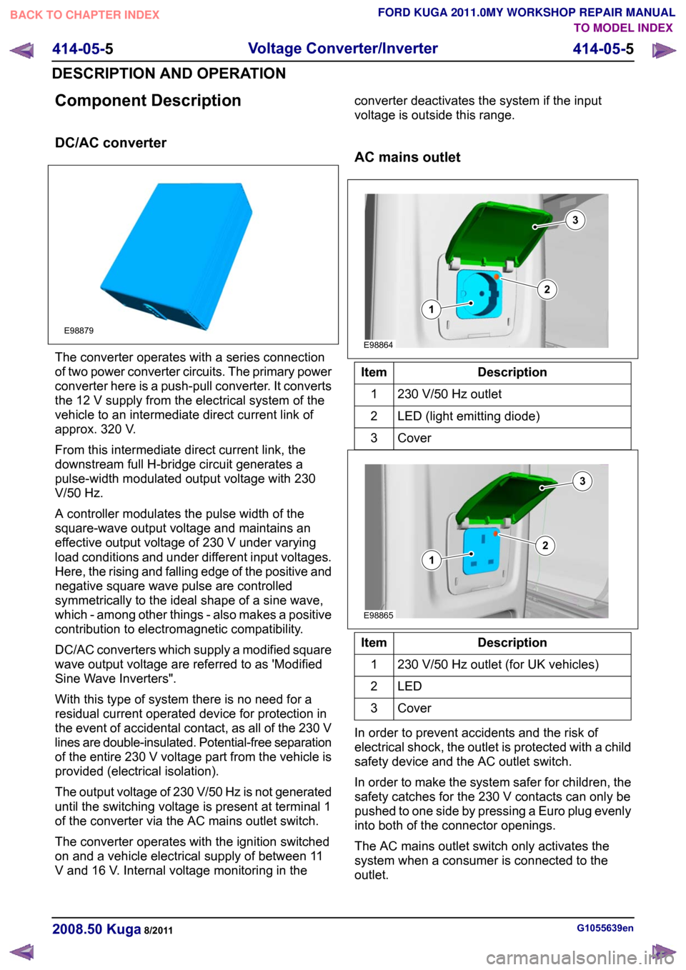
AC mains outlet
Description
Item
230 V/50 Hz outlet
1
LED (light emitting diode)
2
Cover3 Description
Item
230 V/50 Hz outlet (for UK vehicles)
1
LED2
Cover3
In order to prevent accidents and the risk of
electrical shock, the outlet is protected with a child
safety device and the AC outlet switch.
In order to make the system safer for children, the
safety catches for the 230 V contacts can only be
pushed to one side by pressing a Euro plug evenly
into both of the connector openings.
The AC mains outlet switch only activates the
system when a consumer is connected to the
outlet. G1055639en
2008.50 Kuga 8/2011 414-05-5
Voltage Converter/Inverter
414-05-5
DESCRIPTION AND OPERATIONTO MODEL INDEX
BACK TO CHAPTER INDEX
FORD KUGA 2011.0MY WORKSHOP REPAIR MANUALE98879 E98864312 E98865312
Page 384 of 2057

must use the same language. This language is
called a protocol.
At present, Ford uses three different data bus
systems. Depending upon model and equipment
level, all three data bus systems are used. Each
of these data bus systems has its own protocol.
Data bus systems
ISO 9141 bus
The International Organisation for Standardisation
ISO 9141 bus. This consists of a single wire and
is used exclusively for communication between the
modules and the Ford diagnostic unit. The fault
memories of the various modules are read out via
the ISO 9141 bus.
Local Interconnect Network (LIN) bus
The LIN bus is a standard specifically designed for
cost-effective communication between intelligent
sensors and actuators in vehicles. The LIN control
unit subnet is used in every situation where the
bandwidth and versatility of CAN is not needed.
The LIN specification comprises the LIN protocol,
a standard format for describing a complete LIN
and the interface between an LIN and the
application. An LIN comprises a LIN master and
one or more LIN slaves. The LIN utilizes the
master/slave principle for the purpose of bus
access control. This has the significant advantage
that few resources (CPU performance, ROM, RAM)
are required for bus management in the slave
module. The master is implemented in a control
module or a gateway which has the necessary
resources. All communication is initiated by the
master. Consequently, a message always consists
of a header, which is generated by the master, and
a response from the slave. The data transfer rate
is in the region of up to 20 Kbit/s. The LIN master
knows the time sequence of all data which are to
be transmitted. These data are transmitted by the
corresponding LIN slaves (e.g. ultrasonic sensors)
if they are requested to do so by the LIN master.
LIN is a single-wire bus, i.e. the data are
transmitted in the cable via one wire. Usually the
same cable is also used to provide the supply
voltage. The ground connection of the supply
voltage also acts as the ground connection of the
data transmission. An LIN does not use a
terminating resistor.
Controller Area Network (CAN) bus
This consists of two twisted wires and operates
serially (data is transmitted sequentially). It is used
for communication between the modules
themselves and between the modules and the Ford
diagnostic unit. The modules are connected to the
data bus in parallel. New modules can be
incorporated easily, without modifying the other
wiring or modules. The transmitted data is received
by every module connected to the control unit
network (CAN). As each data packet has an
identifier (label), in which the priority of the
message is determined as well as the content
identification, each module can detect whether or
not the data is relevant for its own information
processing. This enables several modules to be
addressed with a particular data packet and
supplied with data simultaneously. For this
purpose, it is ensured that important data (for
example from the ABS) is transmitted first. The
other modules are only able to submit their data to
the data bus after the high-priority messages have
been received.
The advantages of the CAN bus are:
• Minimization of wiring requirements
•
High degree of error protection (fault / fail-proof)
• Robustness
• Good extendibility
• Prioritization of messages
• Inexpensive
• Automatic repetition of faulty messages
• Independent system monitoring and the ability to disconnect faulty modules from the data bus
automatically
Due to the increased number of modules and the
resulting continued increase in data transfer, two
different CAN bus systems are used. Essentially,
they only differ in terms of their data transmission
rates and application areas.
To be able to distinguish between the individual
CAN bus systems, the CAN bus system with the
high transfer speed is called the high speed CAN
bus (HS-CAN). The data are transmitted at a baud
rate of 500 kB/s.
The CAN bus system with the medium transfer
speed is called the medium speed CAN bus
(MS-CAN) and is mainly used for communication
in the comfort electronics or the multimedia system.
The data are transmitted at a baud rate of 125 kB/s.
An interface (gateway) is used to exchange data
between the HS-CAN and the MS-CAN. This
provides the connection between the three CAN
databus systems and is installed in the GEM and
in the electronic instrument cluster. The number of
modules which are connected to the three databus G1030779en
2008.50 Kuga 8/2011 418-00-7
Module Communications Network
418-00-7
DESCRIPTION AND OPERATIONTO MODEL INDEX
BACK TO CHAPTER INDEX
FORD KUGA 2011.0MY WORKSHOP REPAIR MANUAL
Page 1255 of 2057
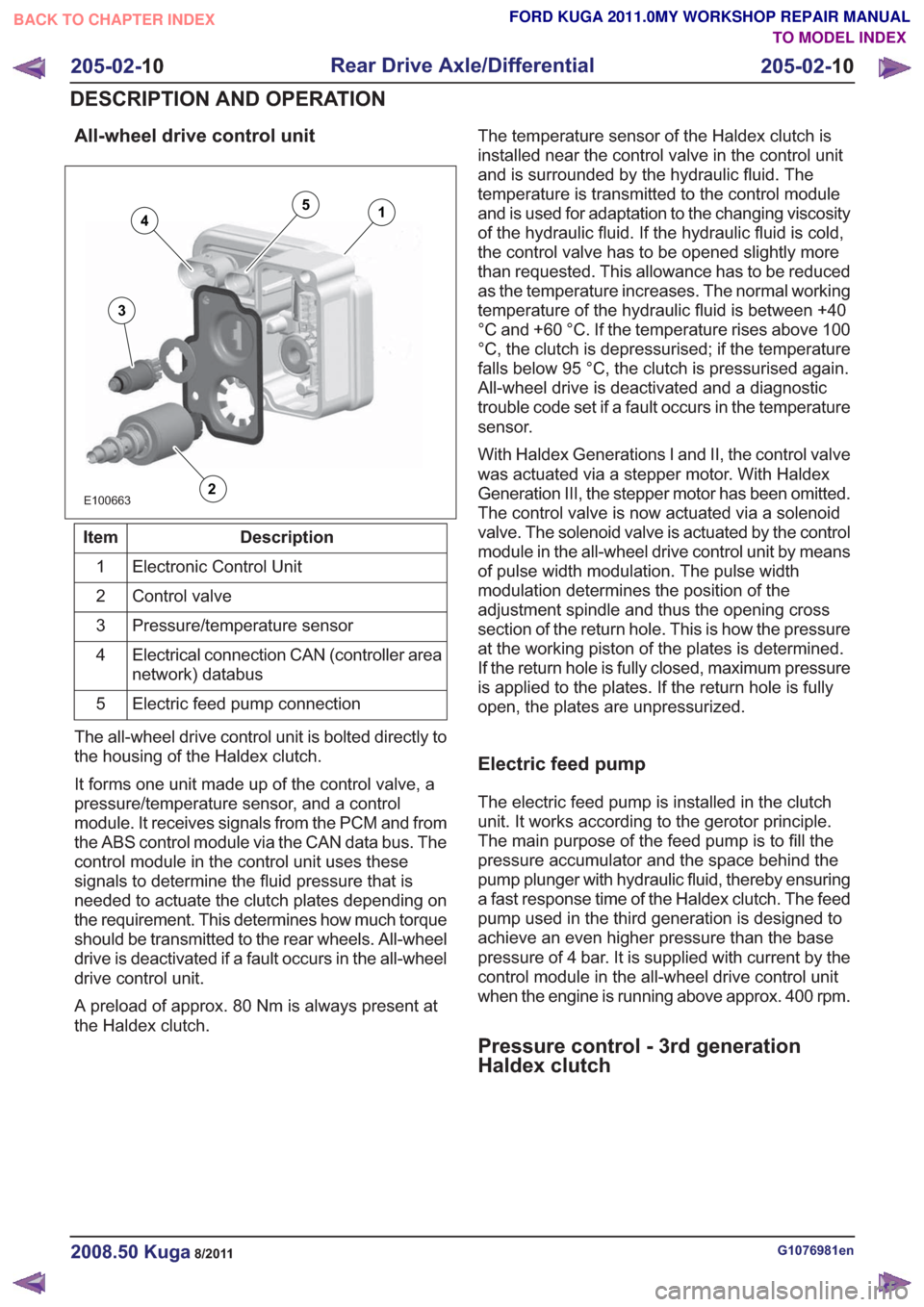
All-wheel drive control unit
E100663
14
3
2
5
Description
Item
Electronic Control Unit
1
Control valve
2
Pressure/temperature sensor
3
Electrical connection CAN (controller area
network) databus
4
Electric feed pump connection
5
The all-wheel drive control unit is bolted directly to
the housing of the Haldex clutch.
It forms one unit made up of the control valve, a
pressure/temperature sensor, and a control
module. It receives signals from the PCM and from
the ABS control module via the CAN data bus. The
control module in the control unit uses these
signals to determine the fluid pressure that is
needed to actuate the clutch plates depending on
the requirement. This determines how much torque
should be transmitted to the rear wheels. All-wheel
drive is deactivated if a fault occurs in the all-wheel
drive control unit.
A preload of approx. 80 Nm is always present at
the Haldex clutch. The temperature sensor of the Haldex clutch is
installed near the control valve in the control unit
and is surrounded by the hydraulic fluid. The
temperature is transmitted to the control module
and is used for adaptation to the changing viscosity
of the hydraulic fluid. If the hydraulic fluid is cold,
the control valve has to be opened slightly more
than requested. This allowance has to be reduced
as the temperature increases. The normal working
temperature of the hydraulic fluid is between +40
°C and +60 °C. If the temperature rises above 100
°C, the clutch is depressurised; if the temperature
falls below 95 °C, the clutch is pressurised again.
All-wheel drive is deactivated and a diagnostic
trouble code set if a fault occurs in the temperature
sensor.
With Haldex Generations I and II, the control valve
was actuated via a stepper motor. With Haldex
Generation III, the stepper motor has been omitted.
The control valve is now actuated via a solenoid
valve. The solenoid valve is actuated by the control
module in the all-wheel drive control unit by means
of pulse width modulation. The pulse width
modulation determines the position of the
adjustment spindle and thus the opening cross
section of the return hole. This is how the pressure
at the working piston of the plates is determined.
If the return hole is fully closed, maximum pressure
is applied to the plates. If the return hole is fully
open, the plates are unpressurized.
Electric feed pump
The electric feed pump is installed in the clutch
unit. It works according to the gerotor principle.
The main purpose of the feed pump is to fill the
pressure accumulator and the space behind the
pump plunger with hydraulic fluid, thereby ensuring
a fast response time of the Haldex clutch. The feed
pump used in the third generation is designed to
achieve an even higher pressure than the base
pressure of 4 bar. It is supplied with current by the
control module in the all-wheel drive control unit
when the engine is running above approx. 400 rpm.
Pressure control - 3rd generation
Haldex clutch
G1076981en2008.50 Kuga8/2011
205-02-
10
Rear Drive Axle/Differential
205-02- 10
DESCRIPTION AND OPERATION
TO MODEL INDEX
BACK TO CHAPTER INDEX
FORD KUGA 2011.0MY WORKSHOP REPAIR MANUAL
Page 1722 of 2057
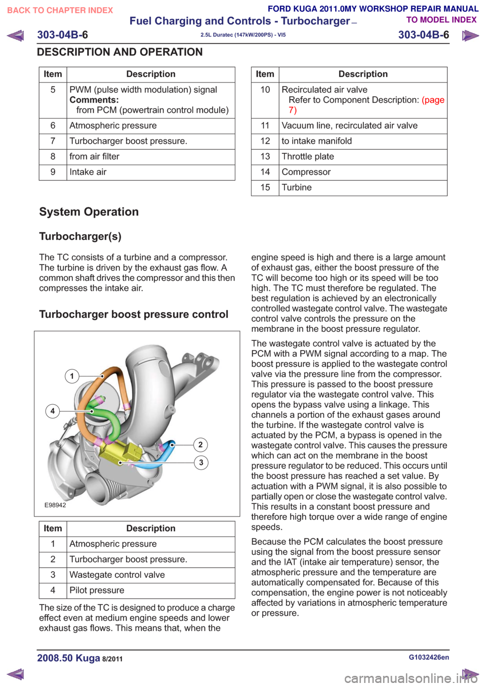
Description
Item
PWM (pulse width modulation) signal
Comments:from PCM (powertrain control module)
5
Atmospheric pressure
6
Turbocharger boost pressure.
7
from air filter
8
Intake air
9Description
Item
Recirculated air valveRefertoComponentDescription:(page
7)
10
Vacuum line, recirculated air valve
11
to intake manifold
12
Throttle plate
13
Compressor
14
Turbine
15
System Operation
Turbocharger(s)
The TC consists of a turbine and a compressor.
The turbine is driven by the exhaust gas flow. A
common shaft drives the compressor and this then
compresses the intake air.
Turbocharger boost pressure control
E98942
1
2
3
4
Description
Item
Atmospheric pressure
1
Turbocharger boost pressure.
2
Wastegate control valve
3
Pilot pressure
4
The size of the TC is designed to produce a charge
effect even at medium engine speeds and lower
exhaust gas flows. This means that, when the engine speed is high and there is a large amount
of exhaust gas, either the boost pressure of the
TC will become too high or its speed will be too
high. The TC must therefore be regulated. The
best regulation is achieved by an electronically
controlled wastegate control valve. The wastegate
control valve controls the pressure on the
membrane in the boost pressure regulator.
The wastegate control valve is actuated by the
PCM with a PWM signal according to a map. The
boost pressure is applied to the wastegate control
valve via the pressure line from the compressor.
This pressure is passed to the boost pressure
regulator via the wastegate control valve. This
opens the bypass valve using a linkage. This
channels a portion of the exhaust gases around
the turbine. If the wastegate control valve is
actuated by the PCM, a bypass is opened in the
wastegate control valve. This causes the pressure
which can act on the membrane in the boost
pressure regulator to be reduced. This occurs until
the boost pressure has reached a set value. By
actuation with a PWM signal, it is also possible to
partially open or close the wastegate control valve.
This results in a constant boost pressure and
therefore high torque over a wide range of engine
speeds.
Because the PCM calculates the boost pressure
using the signal from the boost pressure sensor
and the IAT (intake air temperature) sensor, the
atmospheric pressure and the temperature are
automatically compensated for. Because of this
compensation, the engine power is not noticeably
affected by variations in atmospheric temperature
or pressure.
G1032426en2008.50 Kuga8/2011
303-04B-
6
Fuel Charging and Controls - Turbocharger
—
2.5L Duratec (147kW/200PS) - VI5
303-04B- 6
DESCRIPTION AND OPERATION
TO MODEL INDEX
BACK TO CHAPTER INDEX
FORD KUGA 2011.0MY WORKSHOP REPAIR MANUAL
Page 1782 of 2057
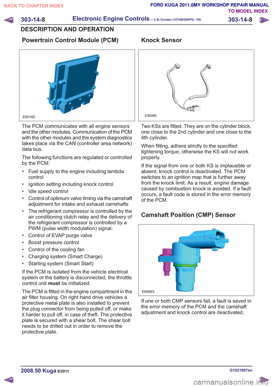
Powertrain Control Module (PCM)
E65160
The PCM communicates with all engine sensors
and the other modules. Communication of the PCM
with the other modules and the system diagnostics
takes place via the CAN (controller area network)
data bus.
The following functions are regulated or controlled
by the PCM:
• Fuel supply to the engine including lambdacontrol
• Ignition setting including knock control
• Idle speed control
• Control of optimum valve timing via the camshaft adjustment for intake and exhaust camshafts
• The refrigerant compressor is controlled by the air conditioning clutch relay and the delivery of
the refrigerant compressor is controlled by a
PWM (pulse width modulation) signal.
• Control of EVAP purge valve
• Boost pressure control
• Control of the cooling fan
• Charging system (Smart Charge)
• Starting system (Smart Start)
If the PCM is isolated from the vehicle electrical
system or the battery is disconnected, the throttle
control unit mustbe initialized.
The PCM is fitted in the engine compartment in the
air filter housing. On right hand drive vehicles a
protective metal plate is also installed to prevent
the plug connector from being pulled off, or make
it harder to pull off, in case of theft. The protective
plate is secured with a shear bolt. The shear bolt
needs to be drilled out in order to remove the
protective plate.
Knock Sensor
E96986
Two KSs are fitted. They are on the cylinder block,
one close to the 2nd cylinder and one close to the
4th cylinder.
When fitting, adhere strictly to the specified
tightening torque, otherwise the KS will not work
properly.
If the signal from one or both KS is implausible or
absent, knock control is deactivated. The PCM
switches to an ignition map that is further away
from the knock limit. As a result, engine damage
caused by combustion knock is avoided. If a fault
occurs, a fault code is stored in the error memory
of the PCM.
Camshaft Position (CMP) Sensor
E89993
If one or both CMP sensors fail, a fault is saved in
the error memory of the PCM and the camshaft
adjustment and knock control are deactivated.
G1021907en2008.50 Kuga8/2011
303-14- 8
Electronic Engine Controls— 2.5L Duratec (147kW/200PS) - VI5303-14-
8
DESCRIPTION AND OPERATION
TO MODEL INDEX
BACK TO CHAPTER INDEX
FORD KUGA 2011.0MY WORKSHOP REPAIR MANUAL
Page 1794 of 2057
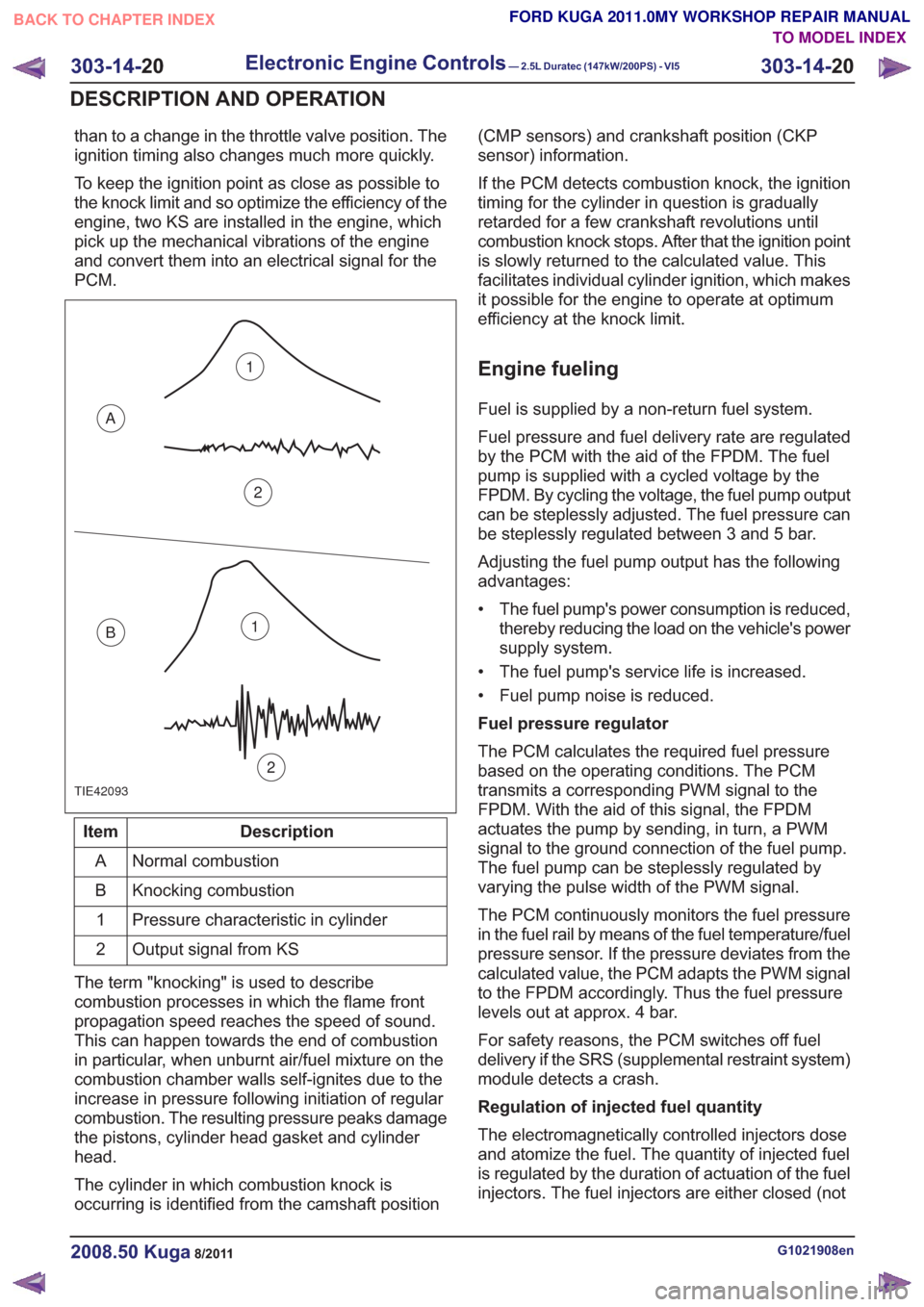
than to a change in the throttle valve position. The
ignition timing also changes much more quickly.
To keep the ignition point as close as possible to
the knock limit and so optimize the efficiency of the
engine, two KS are installed in the engine, which
pick up the mechanical vibrations of the engine
and convert them into an electrical signal for the
PCM.
TIE42093
1
2
A
B1
2
Description
Item
Normal combustion
A
Knocking combustion
B
Pressure characteristic in cylinder
1
Output signal from KS
2
The term "knocking" is used to describe
combustion processes in which the flame front
propagation speed reaches the speed of sound.
This can happen towards the end of combustion
in particular, when unburnt air/fuel mixture on the
combustion chamber walls self-ignites due to the
increase in pressure following initiation of regular
combustion. The resulting pressure peaks damage
the pistons, cylinder head gasket and cylinder
head.
The cylinder in which combustion knock is
occurring is identified from the camshaft position (CMP sensors) and crankshaft position (CKP
sensor) information.
If the PCM detects combustion knock, the ignition
timing for the cylinder in question is gradually
retarded for a few crankshaft revolutions until
combustion knock stops. After that the ignition point
is slowly returned to the calculated value. This
facilitates individual cylinder ignition, which makes
it possible for the engine to operate at optimum
efficiency at the knock limit.
Engine fueling
Fuel is supplied by a non-return fuel system.
Fuel pressure and fuel delivery rate are regulated
by the PCM with the aid of the FPDM. The fuel
pump is supplied with a cycled voltage by the
FPDM. By cycling the voltage, the fuel pump output
can be steplessly adjusted. The fuel pressure can
be steplessly regulated between 3 and 5 bar.
Adjusting the fuel pump output has the following
advantages:
• The fuel pump's power consumption is reduced,
thereby reducing the load on the vehicle's power
supply system.
• The fuel pump's service life is increased.
• Fuel pump noise is reduced.
Fuel pressure regulator
The PCM calculates the required fuel pressure
based on the operating conditions. The PCM
transmits a corresponding PWM signal to the
FPDM. With the aid of this signal, the FPDM
actuates the pump by sending, in turn, a PWM
signal to the ground connection of the fuel pump.
The fuel pump can be steplessly regulated by
varying the pulse width of the PWM signal.
The PCM continuously monitors the fuel pressure
in the fuel rail by means of the fuel temperature/fuel
pressure sensor. If the pressure deviates from the
calculated value, the PCM adapts the PWM signal
to the FPDM accordingly. Thus the fuel pressure
levels out at approx. 4 bar.
For safety reasons, the PCM switches off fuel
delivery if the SRS (supplemental restraint system)
module detects a crash.
Regulation of injected fuel quantity
The electromagnetically controlled injectors dose
and atomize the fuel. The quantity of injected fuel
is regulated by the duration of actuation of the fuel
injectors. The fuel injectors are either closed (not
G1021908en2008.50 Kuga8/2011
303-14- 20
Electronic Engine Controls— 2.5L Duratec (147kW/200PS) - VI5303-14-
20
DESCRIPTION AND OPERATION
TO MODEL INDEX
BACK TO CHAPTER INDEX
FORD KUGA 2011.0MY WORKSHOP REPAIR MANUAL
Page 1796 of 2057
current value is reached. The PCM then
permanently connects the heating element to earth.
The catalyst monitor sensor is used by the PCM
to measure the oxygen content in the exhaust gas
in the TWC. If all the conditions for catalyst
diagnostics are met, based on this information the
PCM can check that the TWC is working
satisfactorily. The information is also used to
improve the air/fuel mixture adjustment.
The catalyst monitor sensor is similar in function
to an HO2S. The signal transmitted by the catalyst
monitor sensor changes sharply if the oxygen
content in the exhaust gas changes. For this
reason, catalyst monitor sensors are also called
"jump lambda sensors".
Fuel tank purging
The EVAP purge valve is only actuated by the PCM
if the coolant temperature is at least 60°C.
Actuation is done ground side by means of a PWM
signal. This makes it possible to have the full range
of opening widths, from fully closed to fully open.
The PCM determines from the operating conditions
when and how wide to open the EVAP tank purge
valve. If the EVAP purge valve is opened, the
engine sucks in ambient air through the activated
charcoal in the evaporative emission canister as
a result of the vacuum in the intake manifold. In
this way the adsorbed hydrocarbons are led to the
combustion chamber of the engine.
The EVAP tank purge valve is not actuated and
system cleaning is interrupted if the engine
switches to idle and/or a closed-loop control
process is initiated.
Power (battery voltage) is supplied via the
Powertrain Control Module relay in the BJB. The
solenoid coil resistance is between 17 and 24 ohms
at 20°C.
Engine speed control
The APP sensor provides the PCM with information
about the driver's request for acceleration.
The throttle control unit receives a corresponding
input signal from the PCM. An electric motor then
moves the throttle valve shaft by means of a set
of gears. The position of the throttle is continuously
recorded by the TP sensor. Information on throttle
position is processed and monitored by the PCM.
The TP sensor comprises two potentiometers.
These work in opposite ways to each other. In one
potentiometer, the resistance increases when the
throttle is opened, in the other it decreases. Thisallows the operation of the potentiometers to be
checked. The signal from the TP sensor is
amplified in the lower range (idle to a quarter open)
by the PCM to enable more precise control of the
throttle in this range. This is necessary because
the engine is very sensitive to changes in throttle
angle in this throttle opening range.
With the throttle valve position kept constant, the
ignition angle and the injected fuel quantity are
then varied to meet the torque demands.
Depending on the operating state of the engine, a
change in the position of the throttle flap may not
be necessary when the APP sensor changes.
If a fault develops in the throttle control unit, a
standby function is executed. This standby function
allows a slight opening of the throttle flap, so that
enough air passes through to allow limited engine
operation. For this purpose, there is a throttle flap
adjustment screw on the throttle housing. The
return spring closes the throttle flap until the stop
of the toothed segment touches the stop screw. In
this way a defined throttle flap gap is formed for
limp home mode.
The stop screw has a spring loaded pin, which
holds the throttle flap open for limp home mode.
In normal operating mode, this spring loaded pin
is pushed in by the force of the electric motor when
the throttle flap must be closed past the limp home
position (e.g. for idle speed control or overrun
shutoff).
Oil monitoring
The engine does not have an oil pressure
switch.
The oil level and oil quality are calculated.
Calculating the engine oil level
The oil level is determined by continuous
measurement of the capacitance (i.e. the ability to
store an electrical charge) between the two
capacitive elements of the engine oil
level/temperature/quality sensor. The different oil
levels cause the capacitance between the elements
to change. The data are recorded by the PCM and
converted into an oil level value. Temporary
fluctuations in oil level are automatically filtered out
by the PCM.
Calculating oil quality
The PCM calculates the oil quality from the oil level
measurement and the oil temperature measured
by the sensor, plus the engine speed and the
average fuel consumption. The driver is informed
about when an oil change is due.
G1021908en2008.50 Kuga8/2011
303-14- 22
Electronic Engine Controls— 2.5L Duratec (147kW/200PS) - VI5303-14-
22
DESCRIPTION AND OPERATION
TO MODEL INDEX
BACK TO CHAPTER INDEX
FORD KUGA 2011.0MY WORKSHOP REPAIR MANUAL
Page 1831 of 2057
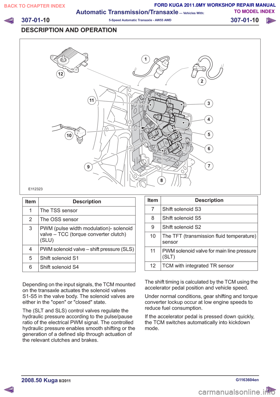
E112323
1
2
7
6
4
5
3
10
9
11
12
Description
Item
The TSS sensor
1
The OSS sensor
2
PWM (pulse width modulation)- solenoid
valve – TCC (torque converter clutch)
(SLU)
3
PWM solenoid valve – shift pressure (SLS)
4
Shift solenoid S1
5
Shift solenoid S4
6Description
Item
Shift solenoid S3
7
Shift solenoid S5
8
Shift solenoid S2
9
The TFT (transmission fluid temperature)
sensor
10
PWM solenoid valve for main line pressure
(SLT)
11
TCM with integrated TR sensor
12
Depending on the input signals, the TCM mounted
on the transaxle actuates the solenoid valves
S1-S5 in the valve body. The solenoid valves are
either in the "open" or "closed" state.
The (SLT and SLS) control valves regulate the
hydraulic pressure according to the pulse/pause
ratio of the electrical PWM signal. The controlled
hydraulic pressure enables smooth shifting or the
generation of a defined slip through actuation of
the relevant clutches and brakes. The shift timing is calculated by the TCM using the
accelerator pedal position and vehicle speed.
Under normal conditions, gear shifting and torque
converter lockup occur at low engine speeds to
reduce fuel consumption.
If the accelerator pedal is pressed down quickly,
the TCM switches automatically into kickdown
mode.
G1163604en2008.50 Kuga8/2011
307-01-
10
Automatic Transmission/Transaxle
— Vehicles With:
5-Speed Automatic Transaxle - AW55 AWD
307-01- 10
DESCRIPTION AND OPERATION
TO MODEL INDEX
BACK TO CHAPTER INDEX
FORD KUGA 2011.0MY WORKSHOP REPAIR MANUAL