fuel cap FORD MONDEO 1993 Service User Guide
[x] Cancel search | Manufacturer: FORD, Model Year: 1993, Model line: MONDEO, Model: FORD MONDEO 1993Pages: 279, PDF Size: 12.71 MB
Page 46 of 279
specifications were available from Ford, but a
typical reading would be in excess of 12 bars.
All cylinders should produce very similar
pressures; any difference greater than 10%
indicates the existence of a fault. Note that the
compression should build up quickly in a
healthy engine; low compression on the first
stroke, followed by gradually-increasing
pressure on successive strokes, indicates worn
piston rings. A low compression reading on the
first stroke, which does not build up during
successive strokes, indicates leaking valves or a
blown head gasket (a cracked head could also
be the cause). Deposits on the undersides of the
valve heads can also cause low compression.
8If the pressure in any cylinder is
considerably lower than the others, introduce
a teaspoonful of clean oil into that cylinder
through its spark plug hole, and repeat the
test.
9If the addition of oil temporarily improves
the compression pressure, this indicates that
bore or piston wear is responsible for the
pressure loss. No improvement suggests that
leaking or burnt valves, or a blown head
gasket, may be to blame.
10A low reading from two adjacent cylinders
is almost certainly due to the head gasket
having blown between them; the presence of
coolant in the engine oil will confirm this.
11If one cylinder is about 20 percent lower
than the others and the engine has a slightly
rough idle, a worn camshaft lobe or faulty
hydraulic tappet could be the cause.
12If the compression is unusually high, the
combustion chambers are probably coated
with carbon deposits. If this is the case, the
cylinder head should be removed and
decarbonised.
13On completion of the test, refit the spark
plugs, then reconnect the ignition system and
fuel pump.
General
1Top Dead Centre (TDC) is the highest point
in its travel up-and-down its cylinder bore
that each piston reaches as the crankshaftrotates. While each piston reaches TDC both
at the top of the compression stroke and
again at the top of the exhaust stroke, for the
purpose of timing the engine, TDC refers to
the piston position (usually No 1 piston) at the
top of its compression stroke.
2It is useful for several servicing procedures
to be able to position the engine at TDC.
3No 1 piston and cylinder are at the right-
hand (timing belt) end of the engine (right-
and left-hand are always quoted as seen from
the driver’s seat). Note that the crankshaft
rotates clockwise when viewed from the
right-hand side of the vehicle.
Locating TDC
4Remove all the spark plugs (Chapter 1).
5Disconnect both battery leads - see
Chapter 5, Section 1 - unless the starter
motor is to be used to turn the engine.
6Apply the handbrake and ensure that the
transmission is in neutral, then jack up the
front right-hand side of the vehicle and
support on an axle stand. Remove the
roadwheel.
7Remove the auxiliary drivebelt cover (see
Chapter 1) to expose the crankshaft pulley
and timing marks.
8It is best to rotate the crankshaft using a
spanner applied to the crankshaft pulley bolt;
however, it is possible also to use the starter
motor (switched on either by an assistant
using the ignition key, or by using a remote
starter switch) to bring the engine close to
TDC, then finish with a spanner. If the starter
is used, be sure to disconnect the battery
leads immediately it is no longer required.
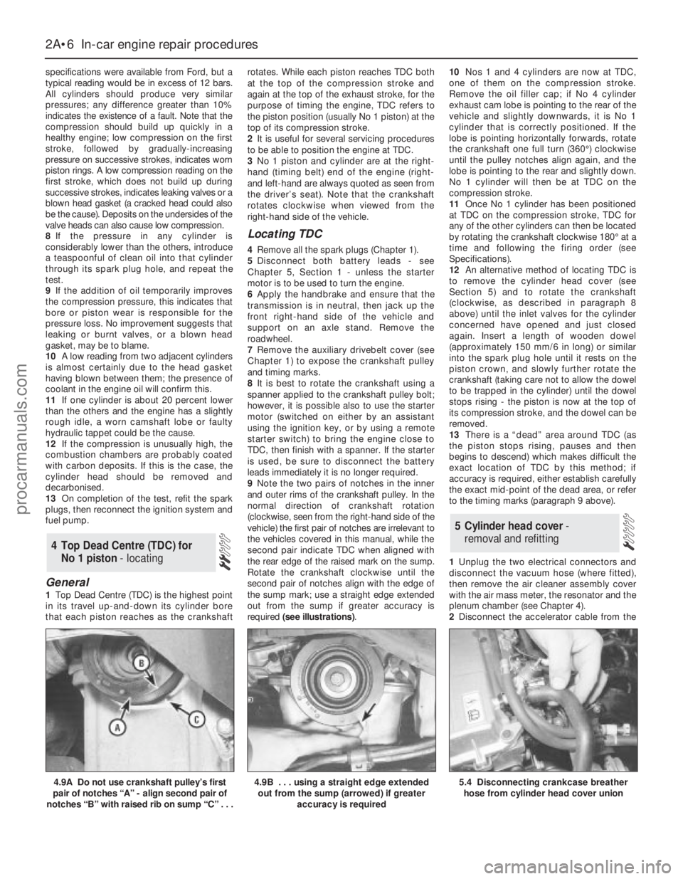
9Note the two pairs of notches in the inner
and outer rims of the crankshaft pulley. In the
normal direction of crankshaft rotation
(clockwise, seen from the right-hand side of the
vehicle) the first pair of notches are irrelevant to
the vehicles covered in this manual, while the
second pair indicate TDC when aligned with
the rear edge of the raised mark on the sump.
Rotate the crankshaft clockwise until the
second pair of notches align with the edge of
the sump mark; use a straight edge extended
out from the sump if greater accuracy is
required (see illustrations).10Nos 1 and 4 cylinders are now at TDC,
one of them on the compression stroke.
Remove the oil filler cap; if No 4 cylinder
exhaust cam lobe is pointing to the rear of the
vehicle and slightly downwards, it is No 1
cylinder that is correctly positioned. If the
lobe is pointing horizontally forwards, rotate
the crankshaft one full turn (360°) clockwise
until the pulley notches align again, and the
lobe is pointing to the rear and slightly down.
No 1 cylinder will then be at TDC on the
compression stroke.
11Once No 1 cylinder has been positioned
at TDC on the compression stroke, TDC for
any of the other cylinders can then be located
by rotating the crankshaft clockwise 180° at a
time and following the firing order (see
Specifications).
12An alternative method of locating TDC is
to remove the cylinder head cover (see
Section 5) and to rotate the crankshaft
(clockwise, as described in paragraph 8
above) until the inlet valves for the cylinder
concerned have opened and just closed
again. Insert a length of wooden dowel
(approximately 150 mm/6 in long) or similar
into the spark plug hole until it rests on the
piston crown, and slowly further rotate the
crankshaft (taking care not to allow the dowel
to be trapped in the cylinder) until the dowel
stops rising - the piston is now at the top of
its compression stroke, and the dowel can be
removed.
13There is a “dead” area around TDC (as
the piston stops rising, pauses and then
begins to descend) which makes difficult the
exact location of TDC by this method; if
accuracy is required, either establish carefully
the exact mid-point of the dead area, or refer
to the timing marks (paragraph 9 above).
1Unplug the two electrical connectors and
disconnect the vacuum hose (where fitted),
then remove the air cleaner assembly cover
with the air mass meter, the resonator and the
plenum chamber (see Chapter 4).
2Disconnect the accelerator cable from the
5 Cylinder head cover-
removal and refitting
4 Top Dead Centre (TDC) for
No 1 piston - locating
2A•6 In-car engine repair procedures
4.9A Do not use crankshaft pulley’s first
pair of notches “A” - align second pair of
notches “B” with raised rib on sump “C” . . .4.9B . . . using a straight edge extended
out from the sump (arrowed) if greater
accuracy is required5.4 Disconnecting crankcase breather
hose from cylinder head cover union
procarmanuals.com
Page 47 of 279
throttle linkage as described in Chapter 4.
Where fitted, disconnect also the cruise
control actuator cable (see Chapter 12).
3Remove the timing belt upper cover (see
Section 9).
4Disconnect the crankcase breather hose
from the cylinder head cover union (see
illustration).
5Unplug the HT leads from the spark plugs
and withdraw them, unclipping the leads from
the cover.
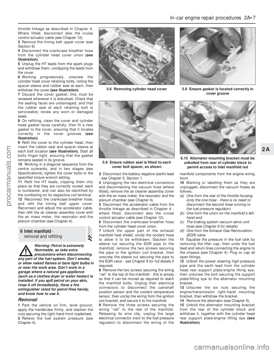
6Working progressively, unscrew the
cylinder head cover retaining bolts, noting the
spacer sleeve and rubber seal at each, then
withdraw the cover (see illustration).
7Discard the cover gasket; this mustbe
renewed whenever it is disturbed. Check that
the sealing faces are undamaged, and that
the rubber seal at each retaining bolt is
serviceable; renew any worn or damaged
seals.
8On refitting, clean the cover and cylinder
head gasket faces carefully, then fit a new
gasket to the cover, ensuring that it locates
correctly in the cover grooves (see
illustration).
9Refit the cover to the cylinder head, then
insert the rubber seal and spacer sleeve at
each bolt location (see illustration). Start all
bolts finger-tight, ensuring that the gasket
remains seated in its groove.
10Working in a diagonal sequence from the
centre outwards, and in two stages (see
Specifications), tighten the cover bolts to the
specified torque wrench setting.
11Refit the HT leads, clipping them into
place so that they are correctly routed; each
is numbered, and can also be identified by
the numbering on its respective coil terminal.
12Reconnect the crankcase breather hose,
and refit the timing belt upper cover.
Reconnect and adjust the accelerator cable,
then refit the air cleaner assembly cover with
the air mass meter, the resonator and the
plenum chamber (see Chapter 4).
Warning: Petrol is extremely
flammable, so take extra
precautions when disconnecting
any part of the fuel system. Don’t smoke,
or allow naked flames or bare light bulbs in
or near the work area. Don’t work in a
garage where a natural gas appliance
(such as a clothes dryer or water heater) is
installed. If you spill petrol on your skin,
rinse it off immediately. Have a fire
extinguisher rated for petrol fires handy,
and know how to use it.
Removal
1Park the vehicle on firm, level ground,
apply the handbrake firmly, and slacken the
nuts securing the right-hand front roadwheel.
2Relieve the fuel system pressure (see
Chapter 4).3Disconnect the battery negative (earth) lead
- see Chapter 5, Section 1.
4Unplugging the two electrical connectors
and disconnecting the vacuum hose (where
fitted), remove the air cleaner assembly cover
with the air mass meter, the resonator and the
plenum chamber (see Chapter 4).
5Disconnect the accelerator cable from the
throttle linkage as described in Chapter 4 -
where fitted, disconnect also the cruise
control actuator cable (see Chapter 12).
6Disconnect the crankcase breather hose
from the cylinder head cover union.
7Unbolt the upper part of the exhaust
manifold heat shield; unclip the coolant hose
to allow it to be withdrawn. Slacken the
sleeve nut securing the EGR pipe to the
manifold, remove the two screws securing
the pipe to the ignition coil bracket, then
unscrew the sleeve nut securing the pipe to
the EGR valve - see Chapter 6 for full details if
required.
8Remove the two screws securing the wiring
“rail” to the top of the manifold - this is simply
so that it can be moved as required to reach
the manifold bolts. Unplug their electrical
connectors to disconnect the camshaft
position sensor and the coolant temperature
sensor, then unclip the wiring from the ignition
coil bracket, and secure it to the manifold.
9Remove the three screws securing the
wiring “rail” to the rear of the manifold.
Releasing its wire clip, unplug the large
electrical connector (next to the fuel pressure
regulator) to disconnect the wiring of themanifold components from the engine wiring
loom.
10Marking or labelling them as they are
unplugged, disconnect the vacuum hoses as
follows:
(a) One from the rear of the throttle housing
(only the one hose - there is no need to
disconnect the second hose running to
the fuel pressure regulator).
(b) One from the union on the manifold’s left-
hand end.
(c) The braking system vacuum servo unit
hose (see Chapter 9 for details).
(d) One from the Exhaust Gas Recirculation
(EGR) valve.
11Equalise the pressure in the fuel tank by
removing the filler cap, then undo the fuel
feed and return lines connecting the engine to
the chassis (see Chapter 4). Plug or cap all
open fittings.
12Unbolt the power steering high-pressure
pipe and the earth lead from the cylinder
head rear support plate/engine lifting eye,
then unscrew the bolt securing the support
plate/lifting eye to the alternator mounting
bracket.
13Unscrew the six nuts securing the
engine/transmission right-hand mounting
bracket, then withdraw the bracket.
14Remove the alternator (see Chapter 5).
15Unbolt the alternator mounting bracket
from the rear of the cylinder block and
withdraw it, together with the cylinder head
rear support plate/engine lifting eye (see
illustration).
6 Inlet manifold -
removal and refitting
In-car engine repair procedures 2A•7
2A
5.8 Ensure gasket is located correctly in
cover groove5.6 Removing cylinder head cover
5.9 Ensure rubber seal is fitted to each
cover bolt spacer, as shown6.15 Alternator mounting bracket must be
unbolted from rear of cylinder block to
permit access to inlet manifold nut
procarmanuals.com
Page 57 of 279
23If using Ford’s recommended procedure,
fit new oil seals to the camshafts as
described in paragraph 5 of Section 12.
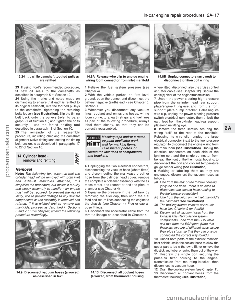
24Using the marks and notes made on
dismantling to ensure that each is refitted to
its original camshaft, refit the toothed pulleys
to the camshafts, tightening the retaining
bolts loosely (see illustration). Slip the timing
belt back onto the pulleys (refer to para-
graph 21 of Section 10) and tighten the bolts
securely - use the forked holding tool
described in paragraph 18 of Section 10.
25The remainder of the reassembly
procedure, including checking the camshaft
alignment (valve timing) and setting the timing
belt tension, is as described in paragraphs 17
to 27 of Section 10.
Removal
Note:The following text assumes that the
cylinder head will be removed with both inlet
and exhaust manifolds attached; this
simplifies the procedure, but makes it a bulky
and heavy assembly to handle - an engine
hoist will be required, to prevent the risk of
injury, and to prevent damage to any delicate
components as the assembly is removed and
refitted. If it is wished first to remove the
manifolds, proceed as described in Sections
6 and 7 of this Chapter; amend the following
procedure accordingly.1Relieve the fuel system pressure (see
Chapter 4).
2With the vehicle parked on firm level
ground, open the bonnet and disconnect the
battery negative (earth) lead - see Chapter 5,
Section 1.
3Whenever you disconnect any vacuum
lines, coolant and emissions hoses, wiring
loom connectors, earth straps and fuel lines
as part of the following procedure, always
label them clearly, so that they can be
correctly reassembled.
4Unplugging the two electrical connectors,
disconnecting the vacuum hose (where fitted)
and disconnecting the crankcase breather
hose from the cylinder head cover, remove
the complete air cleaner assembly with the air
mass meter, the resonator and the plenum
chamber (see Chapter 4).
5Equalise the pressure in the fuel tank by
removing the filler cap, then undo the fuel
feed and return lines connecting the engine to
the chassis (see Chapter 4). Plug or cap all
open fittings.
6Disconnect the accelerator cable from the
throttle linkage as described in Chapter 4 -where fitted, disconnect also the cruise control
actuator cable (see Chapter 12). Secure the
cable(s) clear of the engine/transmission.
7Unbolt the power steering high-pressure
pipe from the cylinder head rear support
plate/engine lifting eye, and from the front
support plate/pump bracket. Releasing its
wire clip, unplug the power steering pressure
switch electrical connector, then unbolt the
earth lead from the cylinder head rear support
plate/engine lifting eye.
8Remove the three screws securing the
wiring “rail” to the rear of the manifold.
Releasing its wire clip, unplug the large
electrical connector (next to the fuel pressure
regulator) to disconnect the engine wiring from
the main loom (see illustration). Unplug the
electrical connectors on each side of the
ignition coil, and the single connector from
beneath the front of the thermostat housing, to
disconnect the coil and coolant temperature
gauge sender wiring (see illustration).
9Marking or labelling them as they are
unplugged, disconnect the vacuum hoses as
follows:
(a) One from the rear of the throttle housing
(only the one hose - there is no need to
disconnect the second hose running to
the fuel pressure regulator).
(b) One from the union on the inlet manifold’s
left-hand end (see illustration).
(c) The braking system vacuum servo unit
hose (see Chapter 9 for details).
(d) Disconnect all vacuum hoses from the
Exhaust Gas Recirculation system
components - one from the EGR valve
and two from the EGR pipe. (Note that
these last two are of different sizes, as are
their pipe stubs, so that they can only be
connected the correct way round.)
10Unbolt both parts of the exhaust manifold
heat shield; unclip the coolant hose to allow the
upper part to be withdrawn. Either remove the
dipstick and tube, or swing them out of the way.
11Unscrew the single bolt securing the
pulse-air filter housing to the engine/
transmission front mounting bracket, then
disconnect its vacuum hose.
12Drain the cooling system (see Chapter 1).
13Disconnect all coolant hoses from the
thermostat housing (see illustration).
14 Cylinder head -
removal and refitting
In-car engine repair procedures 2A•17
2A
14.9 Disconnect vacuum hoses (arrowed)
as described in text14.13 Disconnect all coolant hoses
(arrowed) from thermostat housing
13.24 . . . while camshaft toothed pulleys
are refitted14.8A Release wire clip to unplug engine
wiring loom connector from inlet manifold14.8B Unplug connectors (arrowed) to
disconnect ignition coil wiring
Masking tape and/or a touch-
up paint applicator work
well for marking items.
Take instant photos, or
sketch the locations of components
and brackets.
procarmanuals.com
Page 70 of 279
safely and with relative ease, and which may
have to be hired or borrowed, includes (in
addition to the engine hoist) a heavy-duty trolley
jack, a strong pair of axle stands, some wooden
blocks, and an engine dolly (a low, wheeled
platform capable of taking the weight of the
engine/transmission, so that it can be moved
easily when on the ground). A complete set of
spanners and sockets (as described in the front
of this manual) will obviously be needed,
together with plenty of rags and cleaning
solvent for mopping-up spilled oil, coolant and
fuel. If the hoist is to be hired, make sure that
you arrange for it in advance, and perform all of
the operations possible without it beforehand.
This will save you money and time.
Plan for the vehicle to be out of use for
quite a while. A machine shop will be required
to perform some of the work which the do-it-
yourselfer can’t accomplish without special
equipment. These establishments often have
a busy schedule, so it would be a good idea
to consult them before removing the engine,
to accurately estimate the amount of time
required to rebuild or repair components that
may need work.
Always be extremely careful when removing
and installing the engine/transmission.
Serious injury can result from careless
actions. By planning ahead and taking your
time, the job (although a major task) can be
accomplished successfully.
Warning: Petrol is extremely
flammable, so take extra
precautions when disconnecting
any part of the fuel system. Don’t
smoke, or allow naked flames or bare light
bulbs in or near the work area, and don’t
work in a garage where a natural gas
appliance (such as a clothes dryer or water
heater) is installed. If you spill petrol on
your skin, rinse it off immediately. Have a
fire extinguisher rated for petrol fires
handy, and know how to use it.Note: Read through the entire Section, as well
as reading the advice in the preceding Section,
before beginning this procedure. The engine
and transmission are removed as a unit,
lowered to the ground and removed from
underneath, then separated outside the vehicle.
Removal
1Park the vehicle on firm, level ground, apply
the handbrake firmly, and slacken the nuts
securing both front roadwheels.
2Relieve the fuel system pressure (see
Chapter 4).
3Disconnect the battery negative (earth) lead
- see Chapter 5, Section 1. For better access
the battery may be removed completely (see
Chapter 5).
4Place protective covers on the wings and
engine compartment front crossmember, then
remove the bonnet (see Chapter 11).
5Whenever you disconnect any vacuum
lines, coolant and emissions hoses, wiring
loom connectors, earth straps and fuel lines
as part of the following procedure, always
label them clearly, so that they can be
correctly reassembled.
6Unplug the two electrical connectors,disconnect the vacuum hose (where fitted)
and disconnect the crankcase breather hose
from the cylinder head cover, then remove the
complete air cleaner assembly, with the air
mass meter, the resonator and the plenum
chamber (see Chapter 4).
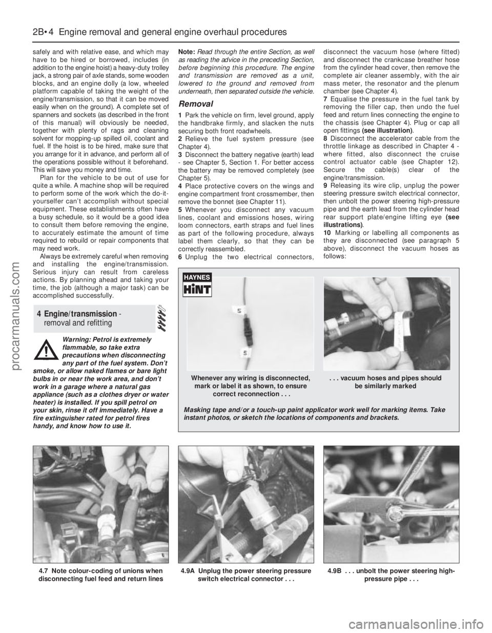
7Equalise the pressure in the fuel tank by
removing the filler cap, then undo the fuel
feed and return lines connecting the engine to
the chassis (see Chapter 4). Plug or cap all
open fittings (see illustration).
8Disconnect the accelerator cable from the
throttle linkage as described in Chapter 4 -
where fitted, also disconnect the cruise
control actuator cable (see Chapter 12).
Secure the cable(s) clear of the
engine/transmission.
9Releasing its wire clip, unplug the power
steering pressure switch electrical connector,
then unbolt the power steering high-pressure
pipe and the earth lead from the cylinder head
rear support plate/engine lifting eye (see
illustrations).
10Marking or labelling all components as
they are disconnected (see paragraph 5
above), disconnect the vacuum hoses as
follows:
4 Engine/transmission -
removal and refitting
2B•4 Engine removal and general engine overhaul procedures
4.7 Note colour-coding of unions when
disconnecting fuel feed and return lines4.9A Unplug the power steering pressure
switch electrical connector . . .4.9B . . . unbolt the power steering high-
pressure pipe . . .
Whenever any wiring is disconnected, . . . vacuum hoses and pipes should
mark or label it as shown, to ensure be similarly marked
correct reconnection . . .
Masking tape and/or a touch-up paint applicator work well for marking items. Take
instant photos, or sketch the locations of components and brackets.
procarmanuals.com
Page 83 of 279
Note:Always check first what replacement
parts are available before planning any
overhaul operation; refer to Section 1 of this
Part. A Ford dealer, or a good engine
reconditioning specialist/automotive parts
supplier may be able to suggest alternatives
which will enable you to overcome the lack of
replacement parts.
1Before the inspection process can be
carried out, the piston/connecting rod
assemblies must be cleaned, and the original
piston rings removed from the pistons. The
rings should have smooth, polished working
surfaces, with no dull or carbon-coated
sections (showing that the ring is not sealing
correctly against the bore wall, so allowing
combustion gases to blow by) and no traces
of wear on their top and bottom surfaces. The
end gaps should be clear of carbon, but not
polished (indicating a too-small end gap), and
all the rings (including the elements of the oil
control ring) should be free to rotate in their
grooves, but without excessive up-and-down
movement. If the rings appear to be in good
condition, they are probably fit for further use;
check the end gaps (in an unworn part of the
bore) as described in Section 16. If any of the
rings appears to be worn or damaged, or has
an end gap significantly different from the
specified value, the usual course of action is
to renew all of them as a set. Note:While it is
usual always to renew piston rings when an
engine is overhauled, this of course assumes
that rings are available separately - if not, it
follows that great care must be taken not to
break or damage any of the rings during the
following procedures, and to ensure that each
ring is marked on removal so that it is refitted
onlythe original way up, and onlyto the same
groove.
2Using a piston ring renoval tool, carefully
remove the rings from the pistons. Be careful
not to nick or gouge the pistons in the
process, and mark or label each ring as it is
removed, so that its original top surface canbe identified on reassembly, and so that it can
be returned to its original groove. Take care
also with your hands - piston rings are sharp!
3Scrape all traces of carbon from the top of
the piston. A hand-held wire brush or a piece
of fine emery cloth can be used, once the
majority of the deposits have been scraped
away. Do not, under any circumstances, use a
wire brush mounted in a drill motor to remove
deposits from the pistons - the piston material
is soft, and may be eroded away by the wire
brush.
4Use a piston ring groove-cleaning tool to
remove carbon deposits from the ring
grooves. If a tool isn’t available, but
replacement rings have been found, a piece
broken off the old ring will do the job. Be very
careful to remove only the carbon deposits -
don’t remove any metal, and do not nick or
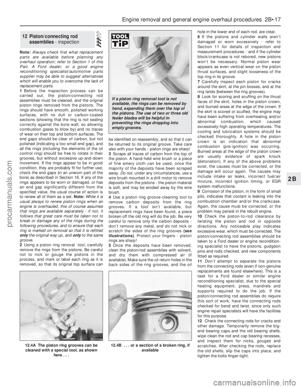
scratch the sides of the ring grooves (see
illustrations). Protect your fingers - piston
rings are sharp!
5Once the deposits have been removed,
clean the piston/rod assemblies with solvent,
and dry them with compressed air (if
available). Make sure the oil return holes in the
back sides of the ring grooves, and the oilhole in the lower end of each rod, are clear.
6If the pistons and cylinder walls aren’t
damaged or worn excessively - refer to
Section 11 for details of inspection and
measurement procedures - and if the cylinder
block/crankcase is not rebored, new pistons
won’t be necessary. Normal piston wear
appears as even vertical wear on the piston
thrust surfaces, and slight looseness of the
top ring in its groove.
7Carefully inspect each piston for cracks
around the skirt, at the pin bosses, and at the
ring lands (between the ring grooves).
8Look for scoring and scuffing on the thrust
faces of the skirt, holes in the piston crown,
and burned areas at the edge of the crown. If
the skirt is scored or scuffed, the engine may
have been suffering from overheating and/or
abnormal combustion, which caused
excessively-high operating temperatures. The
cooling and lubrication systems should be
checked thoroughly. A hole in the piston
crown is an indication that abnormal
combustion (pre-ignition) was occurring.
Burned areas at the edge of the piston crown
are usually evidence of spark knock
(detonation). If any of the above problems
exist, the causes must be corrected, or the
damage will occur again. The causes may
include intake air leaks, incorrect fuel/air
mixture, incorrect ignition timing, or EGR
system malfunctions.
9Corrosion of the piston, in the form of small
pits, indicates that coolant is leaking into the
combustion chamber and/or the crankcase.
Again, the cause must be corrected, or the
problem may persist in the rebuilt engine.
10Check the piston-to-rod clearance by
twisting the piston and rod in opposite
directions. Any noticeable play indicates
excessive wear, which must be corrected. The
piston/connecting rod assemblies should be
taken to a Ford dealer or engine recondition-
ing specialist to have the pistons, gudgeon
pins and rods checked, and new components
fitted as required.
11Don’tattempt to separate the pistons
from the connecting rods (even if non-genuine
replacements are found elsewhere). This is a
task for a Ford dealer or similar engine
reconditioning specialist, due to the special
heating equipment, press, mandrels and
supports required to do the job. If the
piston/connecting rod assemblies do require
this sort of work, have the connecting rods
checked for bend and twist, since only such
engine repair specialists will have the facilities
for this purpose.
12Check the connecting rods for cracks and
other damage. Temporarily remove the big-
end bearing caps and the old bearing shells,
wipe clean the rod and cap bearing recesses,
and inspect them for nicks, gouges and
scratches. After checking the rods, replace
the old shells, slip the caps into place, and
tighten the bolts finger-tight.
12 Piston/connecting rod
assemblies - inspection
Engine removal and general engine overhaul procedures 2B•17
2B
12.4A The piston ring grooves can be
cleaned with a special tool, as shown
here . . .12.4B . . . or a section of a broken ring, if
available
If a piston ring removal tool is not
available, the rings can be removed by
hand, expanding them over the top of
the pistons. The use of two or three old
feeler blades will be helpful in
preventing the rings dropping into
empty grooves.
procarmanuals.com
Page 85 of 279
to the engine bearings, the acid attacks and
corrodes the bearing material.
7Incorrect shell refitting during engine
assembly will lead to bearing failure as well.
Tight-fitting shells leave insufficient bearing
running clearance, and will result in oil
starvation. Dirt or foreign particles trapped
behind a bearing shell result in high spots on
the bearing, which lead to failure. Do not
touch any shell’s bearing surface with your
fingers during reassembly; there is a risk of
scratching the delicate surface, or of
depositing particles of dirt on it.
1Before reassembly begins, ensure that all
new parts have been obtained, and that all
necessary tools are available. Read through
the entire procedure, to familiarise yourself
with the work involved, and to ensure that all
items necessary for reassembly of the engine
are at hand. In addition to all normal tools and
materials, suitable sealant will be required for
two of the joint faces (Ford recommend
Hylosil 102 for the cylinder block/crankcase-
to-sump/oil pump/oil seal carrier joints, and
Loctite 518 for the camshaft right-hand
bearing caps). In all other cases, provided the
relevant mating surfaces are clean and flat,
new gaskets will be sufficient to ensure joints
are oil-tight. Do notuse any kind of silicone-
based sealant on any part of the fuel system
or inlet manifold, and neveruse exhaust
sealants upstream of the catalytic converter.
2In order to save time and avoid problems,
engine reassembly can be carried out in the
following order:
(a) Crankshaft (Section 17).
(b) Piston/connecting rod assemblies
(Section 18).
(c) Oil pump (Part A of this Chapter, Section
16).
(d) Sump (Part A of this Chapter, Section 15).
(e) Flywheel/driveplate (Part A of this
Chapter, Section 21).
(f) Cylinder head (Part A of this Chapter,
Section 14).(g) Timing belt inner cover, tensioner and
toothed pulleys, and timing belt (Part A of
this Chapter).
(h) Engine external components.
3At this stage, all engine components should
be absolutely clean and dry, with all faults
repaired; they should be laid out (or in
individual containers) on a completely-clean
work surface.
1Before installing new piston rings, check
the end gaps. Lay out each piston set with a
piston/connecting rod assembly, and keep
them together as a matched set from now on.
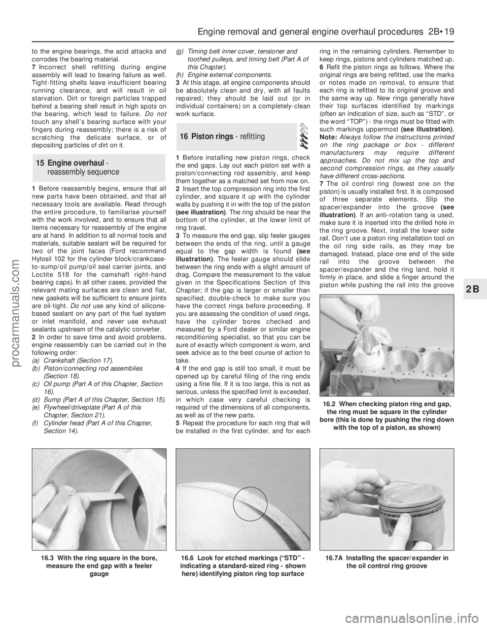
2Insert the top compression ring into the first
cylinder, and square it up with the cylinder
walls by pushing it in with the top of the piston
(see illustration). The ring should be near the
bottom of the cylinder, at the lower limit of
ring travel.
3To measure the end gap, slip feeler gauges
between the ends of the ring, until a gauge
equal to the gap width is found (see
illustration). The feeler gauge should slide
between the ring ends with a slight amount of
drag. Compare the measurement to the value
given in the Specifications Section of this
Chapter; if the gap is larger or smaller than
specified, double-check to make sure you
have the correct rings before proceeding. If
you are assessing the condition of used rings,
have the cylinder bores checked and
measured by a Ford dealer or similar engine
reconditioning specialist, so that you can be
sure of exactly which component is worn, and
seek advice as to the best course of action to
take.
4If the end gap is still too small, it must be
opened up by careful filing of the ring ends
using a fine file. If it is too large, this is not as
serious, unless the specified limit is exceeded,
in which case very careful checking is
required of the dimensions of all components,
as well as of the new parts.
5Repeat the procedure for each ring that will
be installed in the first cylinder, and for eachring in the remaining cylinders. Remember to
keep rings, pistons and cylinders matched up.
6Refit the piston rings as follows. Where the
original rings are being refitted, use the marks
or notes made on removal, to ensure that
each ring is refitted to its original groove and
the same way up. New rings generally have
their top surfaces identified by markings
(often an indication of size, such as “STD”, or
the word “TOP”) - the rings must be fitted with
such markings uppermost (see illustration).
Note:Always follow the instructions printed
on the ring package or box - different
manufacturers may require different
approaches. Do not mix up the top and
second compression rings, as they usually
have different cross-sections.
7The oil control ring (lowest one on the
piston) is usually installed first. It is composed
of three separate elements. Slip the
spacer/expander into the groove (see
illustration). If an anti-rotation tang is used,
make sure it is inserted into the drilled hole in
the ring groove. Next, install the lower side
rail. Don’t use a piston ring installation tool on
the oil ring side rails, as they may be
damaged. Instead, place one end of the side
rail into the groove between the
spacer/expander and the ring land, hold it
firmly in place, and slide a finger around the
piston while pushing the rail into the groove
16 Piston rings - refitting
15 Engine overhaul -
reassembly sequence
Engine removal and general engine overhaul procedures 2B•19
2B
16.7A Installing the spacer/expander in
the oil control ring groove
16.2 When checking piston ring end gap,
the ring must be square in the cylinder
bore (this is done by pushing the ring down
with the top of a piston, as shown)
16.3 With the ring square in the bore,
measure the end gap with a feeler
gauge16.6 Look for etched markings (“STD” -
indicating a standard-sized ring - shown
here) identifying piston ring top surface
procarmanuals.com
Page 88 of 279
rod’s big-end onto the crankpin. The piston
rings may try to pop out of the ring
compressor just before entering the cylinder
bore, so keep some pressure on the ring
compressor. Work slowly, and if any
resistance is felt as the piston enters the
cylinder, stop immediately. Find out what’s
binding, and fix it before proceeding. Do not,
for any reason, force the piston into the
cylinder - you might break a ring and/or the
piston.
10To check the big-end bearing running
clearance, cut a piece of the appropriate-size
Plastigage slightly shorter than the width of
the connecting rod bearing, and lay it in place
on the No 1 crankpin (big-end) journal, parallel
with the crankshaft centre-line (see illus-
tration 17.6).
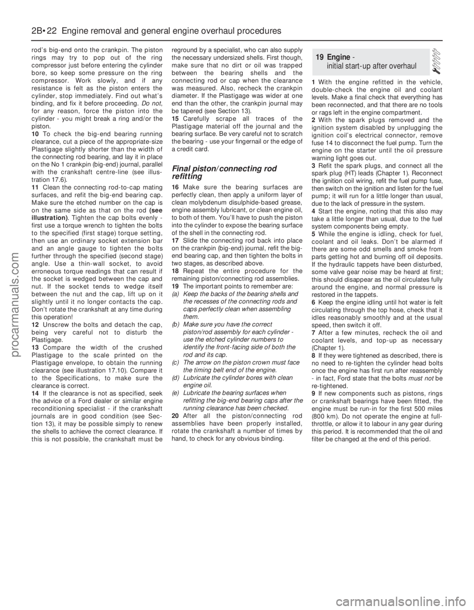
11Clean the connecting rod-to-cap mating
surfaces, and refit the big-end bearing cap.
Make sure the etched number on the cap is
on the same side as that on the rod (see
illustration). Tighten the cap bolts evenly -
first use a torque wrench to tighten the bolts
to the specified (first stage) torque setting,
then use an ordinary socket extension bar
and an angle gauge to tighten the bolts
further through the specified (second stage)
angle. Use a thin-wall socket, to avoid
erroneous torque readings that can result if
the socket is wedged between the cap and
nut. If the socket tends to wedge itself
between the nut and the cap, lift up on it
slightly until it no longer contacts the cap.
Don’t rotate the crankshaft at any time during
this operation!
12Unscrew the bolts and detach the cap,
being very careful not to disturb the
Plastigage.
13Compare the width of the crushed
Plastigage to the scale printed on the
Plastigage envelope, to obtain the running
clearance (see illustration 17.10). Compare it
to the Specifications, to make sure the
clearance is correct.
14If the clearance is not as specified, seek
the advice of a Ford dealer or similar engine
reconditioning specialist - if the crankshaft
journals are in good condition (see Sec-
tion 13), it may be possible simply to renew
the shells to achieve the correct clearance. If
this is not possible, the crankshaft must bereground by a specialist, who can also supply
the necessary undersized shells. First though,
make sure that no dirt or oil was trapped
between the bearing shells and the
connecting rod or cap when the clearance
was measured. Also, recheck the crankpin
diameter. If the Plastigage was wider at one
end than the other, the crankpin journal may
be tapered (see Section 13).
15Carefully scrape all traces of the
Plastigage material off the journal and the
bearing surface. Be very careful not to scratch
the bearing - use your fingernail or the edge of
a credit card.
Final piston/connecting rod
refitting
16Make sure the bearing surfaces are
perfectly clean, then apply a uniform layer of
clean molybdenum disulphide-based grease,
engine assembly lubricant, or clean engine oil,
to both of them. You’ll have to push the piston
into the cylinder to expose the bearing surface
of the shell in the connecting rod.
17Slide the connecting rod back into place
on the crankpin (big-end) journal, refit the big-
end bearing cap, and then tighten the bolts in
two stages, as described above.
18Repeat the entire procedure for the
remaining piston/connecting rod assemblies.
19The important points to remember are:
(a) Keep the backs of the bearing shells and
the recesses of the connecting rods and
caps perfectly clean when assembling
them.
(b) Make sure you have the correct
piston/rod assembly for each cylinder -
use the etched cylinder numbers to
identify the front-facing side of both the
rod and its cap.
(c) The arrow on the piston crown must face
the timing belt end of the engine.
(d) Lubricate the cylinder bores with clean
engine oil.
(e) Lubricate the bearing surfaces when
refitting the big-end bearing caps after the
running clearance has been checked.
20After all the piston/connecting rod
assemblies have been properly installed,
rotate the crankshaft a number of times by
hand, to check for any obvious binding.1With the engine refitted in the vehicle,
double-check the engine oil and coolant
levels. Make a final check that everything has
been reconnected, and that there are no tools
or rags left in the engine compartment.
2With the spark plugs removed and the
ignition system disabled by unplugging the
ignition coil’s electrical connector, remove
fuse 14 to disconnect the fuel pump. Turn the
engine on the starter until the oil pressure
warning light goes out.
3Refit the spark plugs, and connect all the
spark plug (HT) leads (Chapter 1). Reconnect
the ignition coil wiring, refit the fuel pump fuse,
then switch on the ignition and listen for the fuel
pump; it will run for a little longer than usual,
due to the lack of pressure in the system.
4Start the engine, noting that this also may
take a little longer than usual, due to the fuel
system components being empty.
5While the engine is idling, check for fuel,
coolant and oil leaks. Don’t be alarmed if
there are some odd smells and smoke from
parts getting hot and burning off oil deposits.
If the hydraulic tappets have been disturbed,
some valve gear noise may be heard at first;
this should disappear as the oil circulates fully
around the engine, and normal pressure is
restored in the tappets.
6Keep the engine idling until hot water is felt
circulating through the top hose, check that it
idles reasonably smoothly and at the usual
speed, then switch it off.
7After a few minutes, recheck the oil and
coolant levels, and top-up as necessary
(Chapter 1).
8If they were tightened as described, there is
no need to re-tighten the cylinder head bolts
once the engine has first run after reassembly
- in fact, Ford state that the bolts must notbe
re-tightened.
9If new components such as pistons, rings
or crankshaft bearings have been fitted, the
engine must be run-in for the first 500 miles
(800 km). Do not operate the engine at full-
throttle, or allow it to labour in any gear during
this period. It is recommended that the oil and
filter be changed at the end of this period.
19 Engine -
initial start-up after overhaul
2B•22 Engine removal and general engine overhaul procedures
procarmanuals.com
Page 100 of 279
This Chapter is concerned with those
features of the engine management system
that supply clean fuel and air to the engine,
meter it in the required proportions, and
dispose of the results. Since the emission
control sub-systems modify the functions of
both the fuel and exhaust sub-systems, all of
which are integral parts of the whole engine
management system, there are many cross-
references to Chapters 5 and 6. Information
on the electronic control system, its fault
diagnosis, sensors and actuators, is given in
Chapter 6.
The air intake system consists of several
plastics components designed to eliminate
induction roar as much as possible. The air
intake tube (opening behind the direction
indicator/headlight assembly) is connected,
via small and large resonators located under
the front left-hand wing, to the air cleaner
assembly in the engine compartment. Once it
has passed through the filter element and the
air mass meter, the air enters the plenum
chamber mounted above the throttle housing
and inlet manifold; the resonator mounted in
the engine compartment further reduces noise
levels.
The fuel system consists of a plastic tank
(mounted under the body, beneath the rear
seats), combined metal and plastic fuel hoses,
an electric fuel pump mounted in the fuel tank,
and an electronic fuel injection system.
The exhaust system consists of an exhaust
manifold, the front downpipe and catalytic
converter and, on production-fit systems, a
rear section incorporating two or three
silencers and the tailpipe assembly. The
service replacement exhaust system consists
of three or four sections: the front
downpipe/catalytic converter, the
intermediate pipe and front silencer, and the
tailpipe and rear silencer. On some versions,
the tailpipe is in two pieces, with two rear
silencers. The system is suspended
throughout its entire length by rubber
mountings.
Extreme caution should be exercised when
dealing with either the fuel or exhaust
systems. Fuel is a primary element for
combustion. Be very careful! The exhaust
system is an area for exercising caution, as it
operates at very high temperatures. Serious
burns can result from even momentary
contact with any part of the exhaust system,
and the fire risk is ever-present. The catalytic
converter in particular runs at very high
temperatures - refer to the information in
Chapter 6.
Warning: Many of the procedures
in this Chapter require the
removal of fuel lines and
connections, which may result in
some fuel spillage. Petrol is extremely
flammable, so take extra precautionswhen you work on any part of the fuel
system. Don’t smoke, or allow open flames
or bare light bulbs, near the work area.
Don’t work in a garage where a natural
gas-type appliance (such as a water
heater or clothes dryer) with a pilot light is
present. If you spill any fuel on your skin,
rinse it off immediately with soap and
water. When you perform any kind of work
on the fuel system, wear safety glasses,
and have a Class B type fire extinguisher
on hand. Before carrying out any operation
on the fuel system, refer also to the
precautions given in “Safety first!” at the
beginning of this manual, and follow them
implicitly. Petrol is a highly-dangerous and
volatile liquid, and the precautions
necessary when handling it cannot be
overstressed.
Warning: The fuel system will
remain pressurised for long
periods of time after the engine is
switched off - this pressure must
be released before any part of the system
is disturbed. Petrol is extremely
flammable, so take extra precautions
when you work on any part of the fuel
system. Don’t smoke, or allow open flames
or bare light bulbs, near the work area.
Don’t work in a garage where a natural
gas-type appliance (such as a water
heater or clothes dryer) with a pilot light is
present. If you spill any fuel on your skin,
rinse it off immediately with soap and
water. When you perform any kind of work
on the fuel system, wear safety glasses,
and have a Class B type fire extinguisher
on hand.
1The fuel system referred to in this Chapter
is defined as the fuel tank and tank-mounted
fuel pump/fuel gauge sender unit, the fuel
filter, the fuel injectors and the pressure
regulator in the injector rail, and the metal
pipes and flexible hoses of the fuel lines
between these components. All these contain
fuel, which will be under pressure while the
engine is running and/or while the ignition is
switched on.
2The pressure will remain for some time after
the ignition has been switched off, and must
be relieved before any of these components is
disturbed for servicing work.
3The simplest method is simply to
disconnect the fuel pump’s electrical supply
while the engine is running - either by
removing the fuel pump fuse (number 14), or
by lifting the red button on the fuel cut-off
switch (see Section 13) - and to allow the
engine to idle until it dies through lack of fuel
pressure. Turn the engine over once or twice
on the starter to ensure that all pressure is
released, then switch off the ignition; do not
forget to refit the fuse (or depress the redbutton, as appropriate) when work is
complete.
4The Ford method of depressurisation is to
use service tool 29-033 fitted to the fuel rail
pressure test/release fitting - a Schrader-type
valve with a blue plastic cap, located on the
union of the fuel feed line and the fuel rail - to
release the pressure, using a suitable
container and wads of rag to catch the spilt
fuel. Do notsimply depress the valve core to
release fuel pressure - droplets of fuel will
spray out, with a consequent risk of fire, and
of personal injury through fuel getting into
your eyes.
Warning: Either procedure will
merely relieve the increased
pressure necessary for the
engine to run. Remember that
fuel will still be present in the system
components, and take precautions
accordingly before disconnecting any of
them.
5Note that, once the fuel system has been
depressurised and drained (even partially), it
will take significantly longer to restart the
engine - perhaps several seconds of cranking
- before the system is refilled and pressure
restored.
Warning: The fuel system
pressure must be released before
any part of the system is
disturbed - see Section 2. Petrol
is extremely flammable, so take extra
precautions when you work on any part of
the fuel system. Don’t smoke, or allow
open flames or bare light bulbs, near the
work area. Don’t work in a garage where a
natural gas-type appliance (such as a
water heater or clothes dryer) with a pilot
light is present. If you spill any fuel on your
skin, rinse it off immediately with soap and
water. When you perform any kind of work
on the fuel system, wear safety glasses,
and have a Class B type fire extinguisher
on hand.
Disconnecting and connecting
quick-release couplings
1Quick-release couplings are employed at all
unions in the fuel feed and return lines.
2Before disconnecting any fuel system
component, relieve the residual pressure in
the system (see Section 2), and equalise tank
pressure by removing the fuel filler cap.
Warning: This procedure will
merely relieve the increased
pressure necessary for the
engine to run - remember that
fuel will still be present in the system
components, and take precautions
accordingly before disconnecting any of
them.
3 Fuel lines and fittings-
general information
2 Fuel system - depressurisation
1 General information and
precautions
4•2 Fuel and exhaust systems
procarmanuals.com
Page 101 of 279
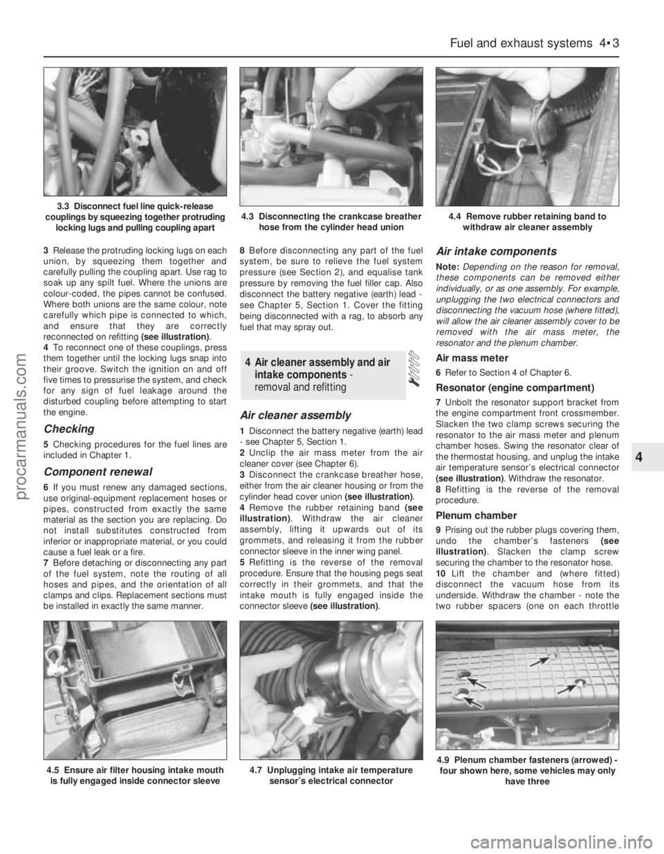
3Release the protruding locking lugs on each
union, by squeezing them together and
carefully pulling the coupling apart. Use rag to
soak up any spilt fuel. Where the unions are
colour-coded, the pipes cannot be confused.
Where both unions are the same colour, note
carefully which pipe is connected to which,
and ensure that they are correctly
reconnected on refitting (see illustration).
4To reconnect one of these couplings, press
them together until the locking lugs snap into
their groove. Switch the ignition on and off
five times to pressurise the system, and check
for any sign of fuel leakage around the
disturbed coupling before attempting to start
the engine.
Checking
5Checking procedures for the fuel lines are
included in Chapter 1.
Component renewal
6If you must renew any damaged sections,
use original-equipment replacement hoses or
pipes, constructed from exactly the same
material as the section you are replacing. Do
not install substitutes constructed from
inferior or inappropriate material, or you could
cause a fuel leak or a fire.
7Before detaching or disconnecting any part
of the fuel system, note the routing of all
hoses and pipes, and the orientation of all
clamps and clips. Replacement sections must
be installed in exactly the same manner.8Before disconnecting any part of the fuel
system, be sure to relieve the fuel system
pressure (see Section 2), and equalise tank
pressure by removing the fuel filler cap. Also
disconnect the battery negative (earth) lead -
see Chapter 5, Section 1. Cover the fitting
being disconnected with a rag, to absorb any
fuel that may spray out.
Air cleaner assembly
1Disconnect the battery negative (earth) lead
- see Chapter 5, Section 1.
2Unclip the air mass meter from the air
cleaner cover (see Chapter 6).
3Disconnect the crankcase breather hose,
either from the air cleaner housing or from the
cylinder head cover union (see illustration).
4Remove the rubber retaining band (see
illustration). Withdraw the air cleaner
assembly, lifting it upwards out of its
grommets, and releasing it from the rubber
connector sleeve in the inner wing panel.
5Refitting is the reverse of the removal
procedure. Ensure that the housing pegs seat
correctly in their grommets, and that the
intake mouth is fully engaged inside the
connector sleeve (see illustration).
Air intake components
Note:Depending on the reason for removal,
these components can be removed either
individually, or as one assembly. For example,
unplugging the two electrical connectors and
disconnecting the vacuum hose (where fitted),
will allow the air cleaner assembly cover to be
removed with the air mass meter, the
resonator and the plenum chamber.
Air mass meter
6Refer to Section 4 of Chapter 6.
Resonator (engine compartment)
7Unbolt the resonator support bracket from
the engine compartment front crossmember.
Slacken the two clamp screws securing the
resonator to the air mass meter and plenum
chamber hoses. Swing the resonator clear of
the thermostat housing, and unplug the intake
air temperature sensor’s electrical connector
(see illustration). Withdraw the resonator.
8Refitting is the reverse of the removal
procedure.
Plenum chamber
9Prising out the rubber plugs covering them,
undo the chamber’s fasteners (see
illustration). Slacken the clamp screw
securing the chamber to the resonator hose.
10Lift the chamber and (where fitted)
disconnect the vacuum hose from its
underside. Withdraw the chamber - note the
two rubber spacers (one on each throttle
4 Air cleaner assembly and air
intake components -
removal and refitting
Fuel and exhaust systems 4•3
4
4.5 Ensure air filter housing intake mouth
is fully engaged inside connector sleeve4.7 Unplugging intake air temperature
sensor’s electrical connector4.9 Plenum chamber fasteners (arrowed) -
four shown here, some vehicles may only
have three
3.3 Disconnect fuel line quick-release
couplings by squeezing together protruding
locking lugs and pulling coupling apart4.3 Disconnecting the crankcase breather
hose from the cylinder head union4.4 Remove rubber retaining band to
withdraw air cleaner assembly
procarmanuals.com
Page 103 of 279
which pulley, disconnect the first cable end
nipple from the throttle actuator’s upper
pulley, then slide the cable outer upwards out
of the actuator housing. Disconnect the
second cable in the same way from the
actuator’s lower pulley.
6Working in the passenger compartment,
reach up to the top of the accelerator pedal.
Pull the end fitting and collar out of the pedal,
then release the cable inner wire through the
slot in the pedal. Tie a length of string to the
end of the cable.
7Returning to the engine compartment, pull
the cable through the bulkhead until the string
can be untied and the pedal-to-actuator cable
removed.
Refitting
8Refitting is the reverse of the removal
procedure. Use the string to draw the pedal-
to-actuator cable through the bulkhead.
Ensure that each cable end is connected to
the correct actuator pulley.
9Adjust both cables as described below.
Adjustment
Note:Both sections of the cable must be
adjusted together, even if only one has been
disturbed.
10Remove the plenum chamber (see
Section 4).
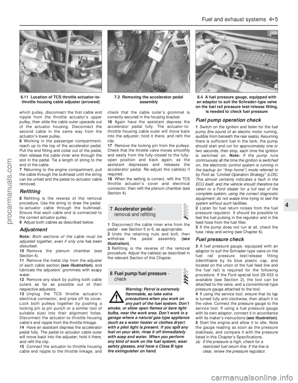
11Remove the metal clip from the adjuster
of each cable section (see illustration), and
lubricate the adjusters’ grommets with soapy
water.
12Remove any slack by pulling both cable
outers as far as possible out of their
respective adjusters.
13Unplug the TCS throttle actuator’s
electrical connector, and prise off its cover.
Lock both pulleys together by pushing a
locking pin (a pin punch or a similar tool of
suitable size) into their alignment holes.
Disconnect the actuator-to-throttle housing
cable’s end nipple from the throttle linkage.
14Have an assistant depress the accelerator
pedal fully. The pedal-to-actuator cable outer
will move back into the adjuster; hold it there,
and refit the clip.
15Connect the actuator-to-throttle housing
cable end nipple to the throttle linkage, andcheck that the cable outer’s grommet is
correctly secured in the housing bracket.
16Again have the assistant depress the
accelerator pedal fully. The actuator-to-
throttle housing cable outer will move back
into the adjuster; hold it there, and refit the
clip.
17Remove the locking pin from the pulleys.
Check that the throttle valve moves smoothly
and easily from the fully-closed to the fully-
open position and back again, as the
assistant depresses and releases the
accelerator pedal. Re-adjust the cable(s) if
required.
18When the setting is correct, refit the TCS
throttle actuator’s cover and electrical
connector, then refit the plenum chamber (see
Section 4).
1Disconnect the cable inner wire from the
pedal - see Section 5 or 6, as appropriate.
2Undo the retaining nuts and bolt, then
withdraw the pedal assembly (see
illustration).
3Refitting is the reverse of the removal
procedure. Adjust the cable(s) as described in
the relevant Section of this Chapter.
Warning: Petrol is extremely
flammable, so take extra
precautions when you work on
any part of the fuel system. Don’t
smoke, or allow open flames or bare light
bulbs, near the work area. Don’t work in a
garage where a natural gas-type appliance
(such as a water heater or clothes dryer)
with a pilot light is present. If you spill any
fuel on your skin, rinse it off immediately
with soap and water. When you perform
any kind of work on the fuel system, wear
safety glasses, and have a Class B type
fire extinguisher on hand.
Fuel pump operation check
1Switch on the ignition and listen for the fuel
pump (the sound of an electric motor running,
audible from beneath the rear seats). Assuming
there is sufficient fuel in the tank, the pump
should start and run for approximately one or
two seconds, then stop, each time the ignition
is switched on. Note:If the pump runs
continuously all the time the ignition is switched
on, the electronic control system is running in
the backup (or “limp-home”) mode referred to
by Ford as “Limited Operation Strategy” (LOS).
This almost certainly indicates a fault in the
ECU itself, and the vehicle should therefore be
taken to a Ford dealer for a full test of the
complete system, using the correct diagnostic
equipment; do not waste time trying to test the
system without such facilities.
2Listen for fuel return noises from the fuel
pressure regulator. It should be possible to
feel the fuel pulsing in the regulator and in the
feed hose from the fuel filter.
3If the pump does not run at all, check the
fuse, relay and wiring (see Chapter 6).
Fuel pressure check
3A fuel pressure gauge, equipped with an
adaptor to suit the Schrader-type valve on the
fuel rail pressure test/release fitting
(identifiable by its blue plastic cap, and
located on the union of the fuel feed line and
the fuel rail) is required for the following
procedure. If the Ford special tool 29-033 is
available (see Section 2), the tool can be
attached to the valve, and a conventional-type
pressure gauge attached to the tool.
4If using the service tool, ensure that its tap
is turned fully anti-clockwise, then attach it to
the valve. Connect the pressure gauge to the
service tool. If using a fuel pressure gauge
with its own adaptor, connect it in accordance
with its maker’s instructions (see illustration).
5Start the engine and allow it to idle. Note
the gauge reading as soon as the pressure
stabilises, and compare it with the pressure
listed in this Chapter’s Specifications.
(a) If the pressure is high, check for a
restricted fuel return line. If the line is
clear, renew the pressure regulator.
8 Fuel pump/fuel pressure -
check
7 Accelerator pedal -
removal and refitting
Fuel and exhaust systems 4•5
4
6.11 Location of TCS throttle actuator-to-
throttle housing cable adjuster (arrowed)7.2 Removing the accelerator pedal
assembly8.4 A fuel pressure gauge, equipped with
an adaptor to suit the Schrader-type valve
on the fuel rail pressure test/release fitting,
is needed to check fuel pressure
procarmanuals.com