fuel cap FORD MONDEO 1993 Service Repair Manual
[x] Cancel search | Manufacturer: FORD, Model Year: 1993, Model line: MONDEO, Model: FORD MONDEO 1993Pages: 279, PDF Size: 12.71 MB
Page 4 of 279
0•4Introduction
Introduced in March 1993, the Ford
Mondeo models are available in four-door
Saloon, five-door Hatchback and five-door
Estate configurations. All feature a high
standard of equipment, with driver/passenger
safety in accidents being a particularly high
design priority; all models are fitted with
features such as side impact bars in all doors,
“anti-submarine” seats combined with “seatbelt grabbers” and pre-tensioners, and an
airbag fitted to the steering wheel. Vehicle
security is enhanced, with an in-built alarm
system and engine immobiliser being fitted as
standard, as well as double-locking doors
with shielded locks, and security-coded audio
equipment.
The four-cylinder petrol engine is a new
design, available in 1.6, 1.8 and 2.0 litrecapacities. It is controlled by a sophisticated
engine management system, which combines
multi-point sequential fuel injection and
distributorless ignition systems with
evaporative emissions control, exhaust gas
recirculation and a three-way regulated
catalytic converter (with a pulse-air system for
rapid warm-up) to ensure that the vehicle
complies with the most stringent of the
emissions control standards currently in force,
and yet provides the levels of performance
and fuel economy expected.
The transversely-mounted engine drives
the front roadwheels through either a five-
speed manual transmission with a cable-
operated clutch, or through an electronically-
controlled four-speed automatic transmission.
The fully-independent suspension is by
MacPherson strut on all four roadwheels,
located by transverse lower arms at the front,
and by transverse and trailing arms at the rear;
anti-roll bars are fitted at front and rear. The
Estate rear suspension is of a different design,
to give maximum loadspace inside the
vehicle, with self-levelling suspension units
available as an option. On some models, the
suspension is electronically-controlled
through the Adaptive Damping System.
The steering is power-assisted, the pump
being belt-driven from the engine, and the
rack-and-pinion steering gear mounted
behind the engine.
The vacuum servo-assisted brakes are disc
at the front, with drums at the rear on most
models; disc rear brakes and an
electronically-controlled Anti-lock Braking
System (ABS) are available on some models,
with a Traction Control System (TCS) available
as a further option where ABS is fitted.
Acknowledgements
Thanks are due to Champion Spark Plug,
who supplied the illustrations showing spark
plug conditions. Certain other illustrations are
the copyright of the Ford Motor Company,
and are used with their permission. Thanks
are also due to Sykes-Pickavant Limited, who
provided some of the workshop tools, and to
all those people at Sparkford who helped in
the production of this manual.
Project vehicles
The main project vehicle used in the
preparation of this manual, and appearing in
many of the photographic sequences, was a
1993-model Ford Mondeo 2.0 Si Hatchback.
Additional work was carried out and
photographed on a 1993-model 2.0 Si Saloon
and a 1993-model 2.0 Ghia Estate (with
automatic transmission).
Introduction to the Ford Mondeo
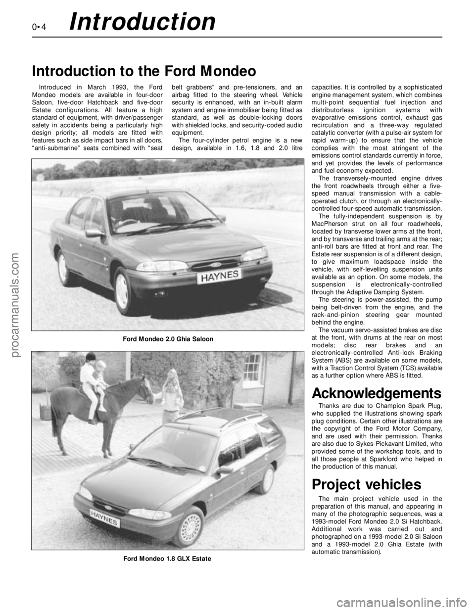
Ford Mondeo 2.0 Ghia Saloon
Ford Mondeo 1.8 GLX Estate
procarmanuals.com
Page 5 of 279
Working on your car can be dangerous.
This page shows just some of the potential
risks and hazards, with the aim of creating a
safety-conscious attitude.
General hazards
Scalding
• Don’t remove the radiator or expansion
tank cap while the engine is hot.
• Engine oil, automatic transmission fluid or
power steering fluid may also be dangerously
hot if the engine has recently been running.
Burning
• Beware of burns from the exhaust system
and from any part of the engine. Brake discs
and drums can also be extremely hot
immediately after use.
Crushing
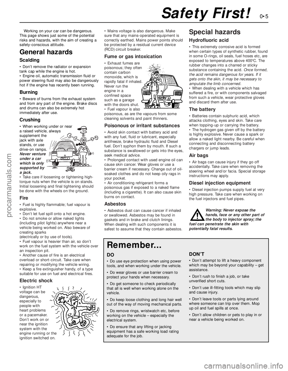
• When working under or near
a raised vehicle, always
supplement the
jack with axle
stands, or use
drive-on ramps.
Never venture
under a car
which is only
supported by
a jack.
• Take care if loosening or tightening high-
torque nuts when the vehicle is on stands.
Initial loosening and final tightening should
be done with the wheels on the ground.
Fire
• Fuel is highly flammable; fuel vapour is
explosive.
• Don’t let fuel spill onto a hot engine.
• Do not smoke or allow naked lights
(including pilot lights) anywhere near a
vehicle being worked on. Also beware of
creating sparks
(electrically or by use of tools).
• Fuel vapour is heavier than air, so don’t
work on the fuel system with the vehicle over
an inspection pit.
• Another cause of fire is an electrical
overload or short-circuit. Take care when
repairing or modifying the vehicle wiring.
• Keep a fire extinguisher handy, of a type
suitable for use on fuel and electrical fires.
Electric shock
• Ignition HT
voltage can be
dangerous,
especially to
people with
heart problems
or a pacemaker.
Don’t work on or
near the ignition
system with the
engine running or the
ignition switched on.• Mains voltage is also dangerous. Make
sure that any mains-operated equipment is
correctly earthed. Mains power points should
be protected by a residual current device
(RCD) circuit breaker.
Fume or gas intoxication
• Exhaust fumes are
poisonous; they often
contain carbon
monoxide, which is
rapidly fatal if inhaled.
Never run the
engine in a
confined space
such as a garage
with the doors shut.
• Fuel vapour is also
poisonous, as are the vapours from some
cleaning solvents and paint thinners.
Poisonous or irritant substances
• Avoid skin contact with battery acid and
with any fuel, fluid or lubricant, especially
antifreeze, brake hydraulic fluid and Diesel
fuel. Don’t syphon them by mouth. If such a
substance is swallowed or gets into the eyes,
seek medical advice.
• Prolonged contact with used engine oil can
cause skin cancer. Wear gloves or use a
barrier cream if necessary. Change out of oil-
soaked clothes and do not keep oily rags in
your pocket.
• Air conditioning refrigerant forms a
poisonous gas if exposed to a naked flame
(including a cigarette). It can also cause skin
burns on contact.
Asbestos
• Asbestos dust can cause cancer if inhaled
or swallowed. Asbestos may be found in
gaskets and in brake and clutch linings.
When dealing with such components it is
safest to assume that they contain asbestos.
Special hazards
Hydrofluoric acid
• This extremely corrosive acid is formed
when certain types of synthetic rubber, found
in some O-rings, oil seals, fuel hoses etc, are
exposed to temperatures above 400
0C. The
rubber changes into a charred or sticky
substance containing the acid. Once formed,
the acid remains dangerous for years. If it
gets onto the skin, it may be necessary to
amputate the limb concerned.
• When dealing with a vehicle which has
suffered a fire, or with components salvaged
from such a vehicle, wear protective gloves
and discard them after use.
The battery
• Batteries contain sulphuric acid, which
attacks clothing, eyes and skin. Take care
when topping-up or carrying the battery.
• The hydrogen gas given off by the battery
is highly explosive. Never cause a spark or
allow a naked light nearby. Be careful when
connecting and disconnecting battery
chargers or jump leads.
Air bags
• Air bags can cause injury if they go off
accidentally. Take care when removing the
steering wheel and/or facia. Special storage
instructions may apply.
Diesel injection equipment
• Diesel injection pumps supply fuel at very
high pressure. Take care when working on
the fuel injectors and fuel pipes.
Warning: Never expose the
hands, face or any other part of
the body to injector spray; the
fuel can penetrate the skin with
potentially fatal results.
Remember...
DO
• Do use eye protection when using power
tools, and when working under the vehicle.
• Do wear gloves or use barrier cream to
protect your hands when necessary.
• Do get someone to check periodically
that all is well when working alone on the
vehicle.
• Do keep loose clothing and long hair well
out of the way of moving mechanical parts.
• Do remove rings, wristwatch etc, before
working on the vehicle – especially the
electrical system.
• Do ensure that any lifting or jacking
equipment has a safe working load rating
adequate for the job.
A few tips
DON’T
• Don’t attempt to lift a heavy component
which may be beyond your capability – get
assistance.
• Don’t rush to finish a job, or take
unverified short cuts.
• Don’t use ill-fitting tools which may slip
and cause injury.
• Don’t leave tools or parts lying around
where someone can trip over them. Mop
up oil and fuel spills at once.
• Don’t allow children or pets to play in or
near a vehicle being worked on.
0•5Safety First!
procarmanuals.com
Page 10 of 279
0•10
MExamine the handbrake mechanism,
checking for frayed or broken cables,
excessive corrosion, or wear or insecurity of
the linkage. Check that the mechanism works
on each relevant wheel, and releases fully,
without binding.
MIt is not possible to test brake efficiency
without special equipment, but a road test
can be carried out later to check that the
vehicle pulls up in a straight line.
Fuel and exhaust systems
MInspect the fuel tank (including the filler
cap), fuel pipes, hoses and unions. All
components must be secure and free from
leaks.
MExamine the exhaust system over its entire
length, checking for any damaged, broken or
missing mountings, security of the retaining
clamps and rust or corrosion.
Wheels and tyres
MExamine the sidewalls and tread area of
each tyre in turn. Check for cuts, tears, lumps,
bulges, separation of the tread, and exposure
of the ply or cord due to wear or damage.
Check that the tyre bead is correctly seated
on the wheel rim, that the valve is sound andproperly seated, and that the wheel is not
distorted or damaged.
MCheck that the tyres are of the correct size
for the vehicle, that they are of the same size
and type on each axle, and that the pressures
are correct.
MCheck the tyre tread depth. The legal
minimum at the time of writing is 1.6 mm over
at least three-quarters of the tread width.
Abnormal tread wear may indicate incorrect
front wheel alignment.
Body corrosion
MCheck the condition of the entire vehicle
structure for signs of corrosion in load-
bearing areas. (These include chassis box
sections, side sills, cross-members, pillars,
and all suspension, steering, braking system
and seat belt mountings and anchorages.)
Any corrosion which has seriously reduced
the thickness of a load-bearing area is likely to
cause the vehicle to fail. In this case
professional repairs are likely to be needed.
MDamage or corrosion which causes sharp
or otherwise dangerous edges to be exposed
will also cause the vehicle to fail.
Petrol models
MHave the engine at normal operating
temperature, and make sure that it is in good
tune (ignition system in good order, air filter
element clean, etc).
MBefore any measurements are carried out,
raise the engine speed to around 2500 rpm,
and hold it at this speed for 20 seconds. Allow
the engine speed to return to idle, and watchfor smoke emissions from the exhaust
tailpipe. If the idle speed is obviously much
too high, or if dense blue or clearly-visible
black smoke comes from the tailpipe for more
than 5 seconds, the vehicle will fail. As a rule
of thumb, blue smoke signifies oil being burnt
(engine wear) while black smoke signifies
unburnt fuel (dirty air cleaner element, or other
carburettor or fuel system fault).
MAn exhaust gas analyser capable of
measuring carbon monoxide (CO) and
hydrocarbons (HC) is now needed. If such an
instrument cannot be hired or borrowed, a
local garage may agree to perform the check
for a small fee.
CO emissions (mixture)
MAt the time or writing, the maximum CO
level at idle is 3.5% for vehicles first used after
August 1986 and 4.5% for older vehicles.
From January 1996 a much tighter limit
(around 0.5%) applies to catalyst-equipped
vehicles first used from August 1992. If the
CO level cannot be reduced far enough to
pass the test (and the fuel and ignition
systems are otherwise in good condition) then
the carburettor is badly worn, or there is some
problem in the fuel injection system or
catalytic converter (as applicable).
HC emissionsMWith the CO emissions within limits, HC
emissions must be no more than 1200 ppm
(parts per million). If the vehicle fails this test
at idle, it can be re-tested at around 2000
rpm; if the HC level is then 1200 ppm or less,
this counts as a pass.
MExcessive HC emissions can be caused by
oil being burnt, but they are more likely to be
due to unburnt fuel.
Diesel models
MThe only emission test applicable to Diesel
engines is the measuring of exhaust smoke
density. The test involves accelerating the
engine several times to its maximum
unloaded speed.
Note: It is of the utmost importance that the
engine timing belt is in good condition before
the test is carried out.
M
Excessive smoke can be caused by a dirty
air cleaner element. Otherwise, professional
advice may be needed to find the cause.
4Checks carried out on
YOUR VEHICLE’S EXHAUST
EMISSION SYSTEM
MOT Test Checks
procarmanuals.com
Page 14 of 279
0•14Conversion Factors
Length (distance)
Inches (in) x 25.4 = Millimetres (mm) x 0.0394 = Inches (in)
Feet (ft) x 0.305 = Metres (m) x 3.281 = Feet (ft)
Miles x 1.609 = Kilometres (km) x 0.621 = Miles
Volume (capacity)
Cubic inches (cu in; in3) x 16.387 = Cubic centimetres (cc; cm3) x 0.061 = Cubic inches (cu in; in3)
Imperial pints (Imp pt) x 0.568 = Litres (l) x 1.76 = Imperial pints (Imp pt)
Imperial quarts (Imp qt) x 1.137 = Litres (l) x 0.88 = Imperial quarts (Imp qt)
Imperial quarts (Imp qt) x 1.201 = US quarts (US qt) x 0.833 = Imperial quarts (Imp qt)
US quarts (US qt) x 0.946 = Litres (l) x 1.057 = US quarts (US qt)
Imperial gallons (Imp gal) x 4.546 = Litres (l) x 0.22 = Imperial gallons (Imp gal)
Imperial gallons (Imp gal) x 1.201 = US gallons (US gal) x 0.833 = Imperial gallons (Imp gal)
US gallons (US gal) x 3.785 = Litres (l) x 0.264 = US gallons (US gal)
Mass (weight)
Ounces (oz) x 28.35 = Grams (g) x 0.035 = Ounces (oz)
Pounds (lb) x 0.454 = Kilograms (kg) x 2.205 = Pounds (lb)
Force
Ounces-force (ozf; oz) x 0.278 = Newtons (N) x 3.6 = Ounces-force (ozf; oz)
Pounds-force (lbf; lb) x 4.448 = Newtons (N) x 0.225 = Pounds-force (lbf; lb)
Newtons (N) x 0.1 = Kilograms-force (kgf; kg) x 9.81 = Newtons (N)
Pressure
Pounds-force per square inch x 0.070 = Kilograms-force per square x 14.223 = Pounds-force per square inch
(psi; lbf/in2; lb/in2) centimetre (kgf/cm2; kg/cm2) (psi; lbf/in2; lb/in2)
Pounds-force per square inch x 0.068 = Atmospheres (atm) x 14.696 = Pounds-force per square inch
(psi; lbf/in
2; lb/in2)(psi; lbf/in2; lb/in2)
Pounds-force per square inch x 0.069 = Bars x 14.5 = Pounds-force per square inch
(psi; lbf/in
2; lb/in2)(psi; lbf/in2; lb/in2)
Pounds-force per square inch x 6.895 = Kilopascals (kPa) x 0.145 = Pounds-force per square inch
(psi; lbf/in
2; lb/in2)(psi; lbf/in2; lb/in2)
Kilopascals (kPa) x 0.01 = Kilograms-force per square x 98.1 = Kilopascals (kPa)
centimetre (kgf/cm
2; kg/cm2)
Millibar (mbar) x 100 = Pascals (Pa) x 0.01 = Millibar (mbar)
Millibar (mbar) x 0.0145 = Pounds-force per square inch x 68.947 = Millibar (mbar)
(psi; lbf/in
2; lb/in2)
Millibar (mbar) x 0.75 = Millimetres of mercury (mmHg) x 1.333 = Millibar (mbar)
Millibar (mbar) x 0.401 = Inches of water (inH
2O) x 2.491 = Millibar (mbar)
Millimetres of mercury (mmHg) x 0.535 = Inches of water (inH
2O) x 1.868 = Millimetres of mercury (mmHg)
Inches of water (inH
2O) x 0.036 = Pounds-force per square inch x 27.68 = Inches of water (inH2O)
(psi; lbf/in2; lb/in2)
Torque (moment of force)
Pounds-force inches x 1.152 = Kilograms-force centimetre x 0.868 = Pounds-force inches
(lbf in; lb in) (kgf cm; kg cm) (lbf in; lb in)
Pounds-force inches x 0.113 = Newton metres (Nm) x 8.85 = Pounds-force inches
(lbf in; lb in)(lbf in; lb in)
Pounds-force inches x 0.083 = Pounds-force feet (lbf ft; lb ft) x 12 = Pounds-force inches
(lbf in; lb in)(lbf in; lb in)
Pounds-force feet (lbf ft; lb ft) x 0.138 = Kilograms-force metres x 7.233 = Pounds-force feet (lbf ft; lb ft)
(kgf m; kg m)
Pounds-force feet (lbf ft; lb ft) x 1.356 = Newton metres (Nm) x 0.738 = Pounds-force feet (lbf ft; lb ft)
Newton metres (Nm) x 0.102 = Kilograms-force metres x 9.804 = Newton metres (Nm)
(kgf m; kg m)
Power
Horsepower (hp) x 745.7 = Watts (W) x 0.0013 = Horsepower (hp)
Velocity (speed)
Miles per hour (miles/hr; mph) x 1.609 = Kilometres per hour (km/hr; kph) x 0.621 = Miles per hour (miles/hr; mph)
Fuel consumption*
Miles per gallon (mpg) x 0.354 = Kilometres per litre (km/l) x 2.825 = Miles per gallon (mpg)
Temperature
Degrees Fahrenheit = (°C x 1.8) + 32 Degrees Celsius (Degrees Centigrade; °C) = (°F - 32) x 0.56
* It is common practice to convert from miles per gallon (mpg) to litres/100 kilometres (l/100km), where mpg x l/100 km = 282
procarmanuals.com
Page 16 of 279
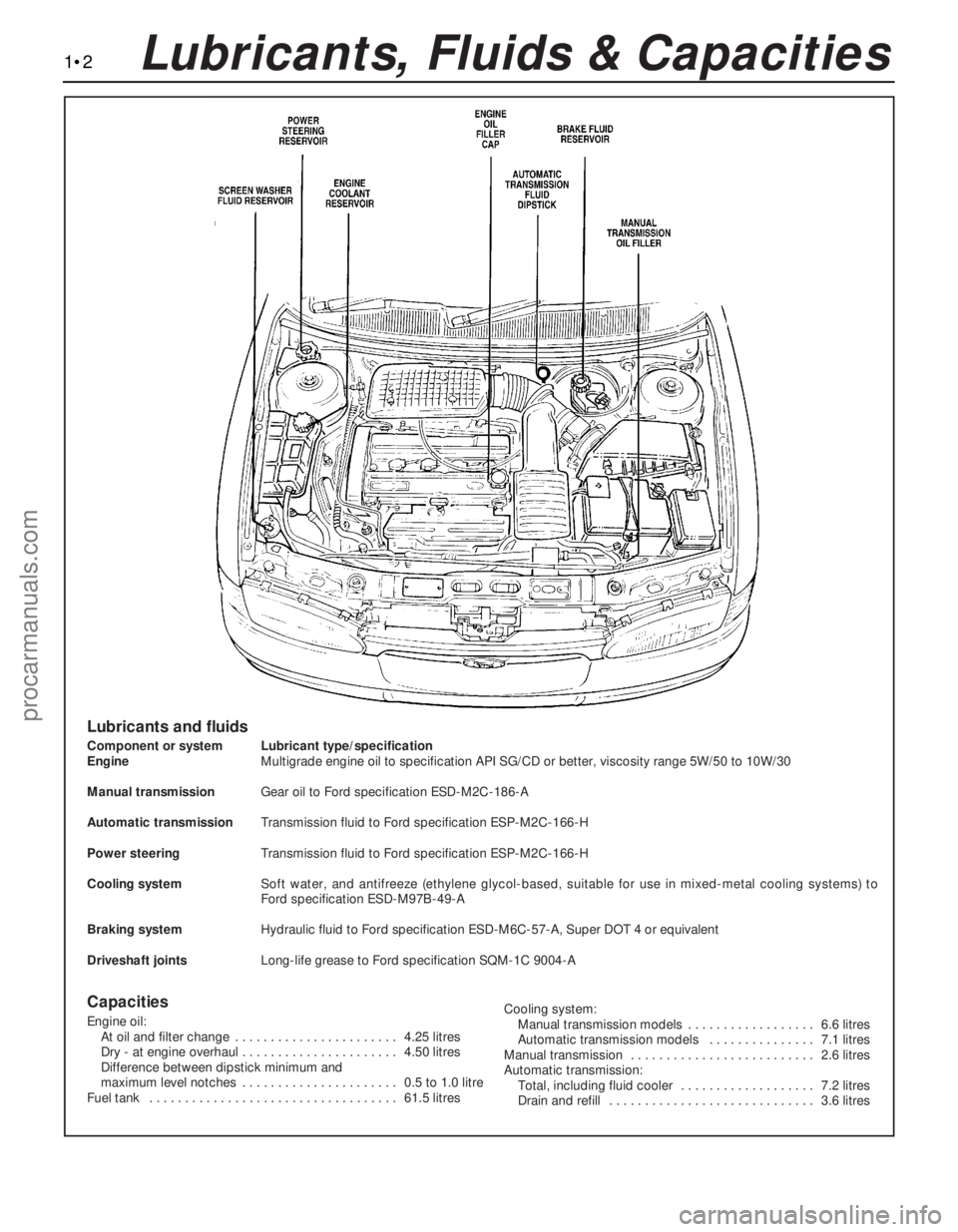
1•2Lubricants, Fluids & Capacities
Lubricants and fluids
Component or system Lubricant type/specification
EngineMultigrade engine oil to specification API SG/CD or better, viscosity range 5W/50 to 10W/30
Manual transmissionGear oil to Ford specification ESD-M2C-186-A
Automatic transmissionTransmission fluid to Ford specification ESP-M2C-166-H
Power steeringTransmission fluid to Ford specification ESP-M2C-166-H
Cooling systemSoft water, and antifreeze (ethylene glycol-based, suitable for use in mixed-metal cooling systems) to
Ford specification ESD-M97B-49-A
Braking systemHydraulic fluid to Ford specification ESD-M6C-57-A, Super DOT 4 or equivalent
Driveshaft jointsLong-life grease to Ford specification SQM-1C 9004-A
Capacities
Engine oil:
At oil and filter change . . . . . . . . . . . . . . . . . . . . . . . 4.25 litres
Dry - at engine overhaul . . . . . . . . . . . . . . . . . . . . . . 4.50 litres
Difference between dipstick minimum and
maximum level notches . . . . . . . . . . . . . . . . . . . . . . 0.5 to 1.0 litre
Fuel tank . . . . . . . . . . . . . . . . . . . . . . . . . . . . . . . . . . . 61.5 litresCooling system:
Manual transmission models . . . . . . . . . . . . . . . . . . 6.6 litres
Automatic transmission models . . . . . . . . . . . . . . . 7.1 litres
Manual transmission . . . . . . . . . . . . . . . . . . . . . . . . . . 2.6 litres
Automatic transmission:
Total, including fluid cooler . . . . . . . . . . . . . . . . . . . 7.2 litres
Drain and refill . . . . . . . . . . . . . . . . . . . . . . . . . . . . . 3.6 litres
procarmanuals.com
Page 18 of 279
1•4
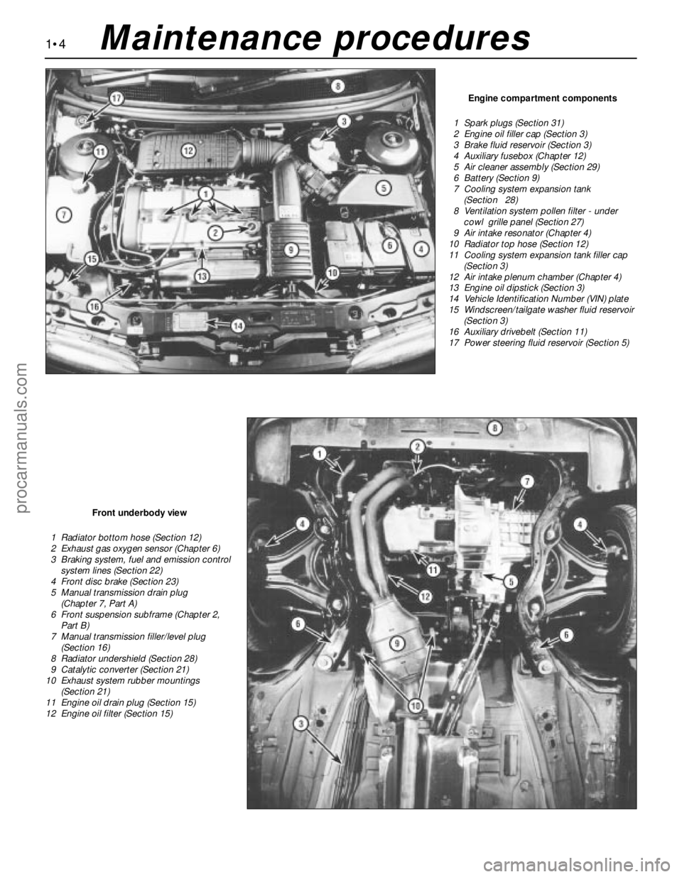
Engine compartment components
1 Spark plugs (Section 31)
2 Engine oil filler cap (Section 3)
3 Brake fluid reservoir (Section 3)
4 Auxiliary fusebox (Chapter 12)
5 Air cleaner assembly (Section 29)
6 Battery (Section 9)
7 Cooling system expansion tank
(Section 28)
8 Ventilation system pollen filter - under
cowl grille panel (Section 27)
9 Air intake resonator (Chapter 4)
10 Radiator top hose (Section 12)
11 Cooling system expansion tank filler cap
(Section 3)
12 Air intake plenum chamber (Chapter 4)
13 Engine oil dipstick (Section 3)
14 Vehicle Identification Number (VIN) plate
15 Windscreen/tailgate washer fluid reservoir
(Section 3)
16 Auxiliary drivebelt (Section 11)
17 Power steering fluid reservoir (Section 5)
Front underbody view
1 Radiator bottom hose (Section 12)
2 Exhaust gas oxygen sensor (Chapter 6)
3 Braking system, fuel and emission control
system lines (Section 22)
4 Front disc brake (Section 23)
5 Manual transmission drain plug
(Chapter 7, Part A)
6 Front suspension subframe (Chapter 2,
Part B)
7 Manual transmission filler/level plug
(Section 16)
8 Radiator undershield (Section 28)
9 Catalytic converter (Section 21)
10 Exhaust system rubber mountings
(Section 21)
11 Engine oil drain plug (Section 15)
12 Engine oil filter (Section 15)
Maintenance procedures
procarmanuals.com
Page 20 of 279
This Chapter is designed to help the home
mechanic maintain the Ford Mondeo models
for peak performance, economy, safety and
long life.
On the following pages are Sections
dealing specifically with each item on the
maintenance schedule. Visual checks,
adjustments, component replacement and
other helpful items are included. Refer to the
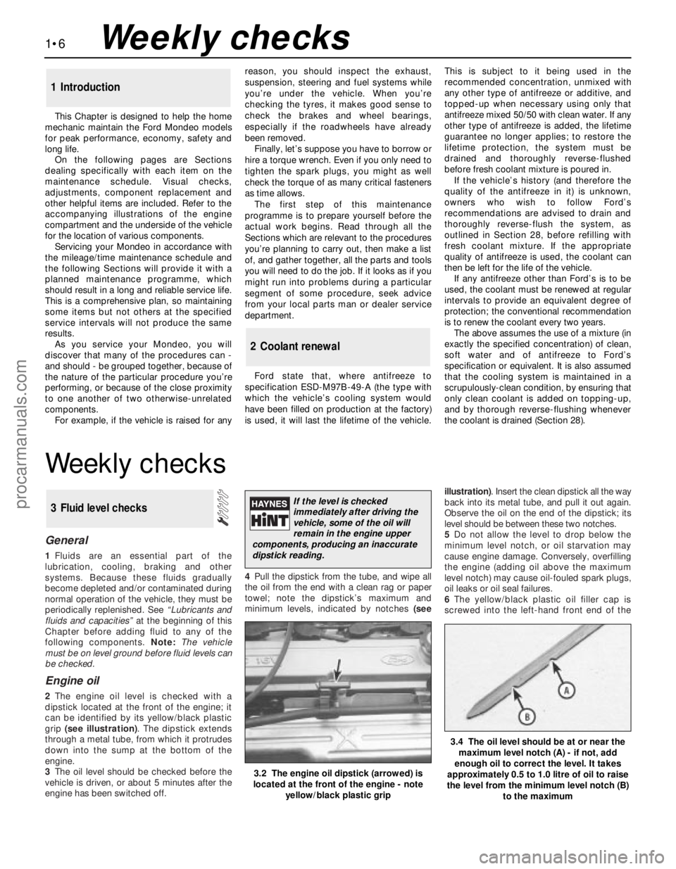
accompanying illustrations of the engine
compartment and the underside of the vehicle
for the location of various components.
Servicing your Mondeo in accordance with
the mileage/time maintenance schedule and
the following Sections will provide it with a
planned maintenance programme, which
should result in a long and reliable service life.
This is a comprehensive plan, so maintaining
some items but not others at the specified
service intervals will not produce the same
results.
As you service your Mondeo, you will
discover that many of the procedures can -
and should - be grouped together, because of
the nature of the particular procedure you’re
performing, or because of the close proximity
to one another of two otherwise-unrelated
components.
For example, if the vehicle is raised for anyreason, you should inspect the exhaust,
suspension, steering and fuel systems while
you’re under the vehicle. When you’re
checking the tyres, it makes good sense to
check the brakes and wheel bearings,
especially if the roadwheels have already
been removed.
Finally, let’s suppose you have to borrow or
hire a torque wrench. Even if you only need to
tighten the spark plugs, you might as well
check the torque of as many critical fasteners
as time allows.
The first step of this maintenance
programme is to prepare yourself before the
actual work begins. Read through all the
Sections which are relevant to the procedures
you’re planning to carry out, then make a list
of, and gather together, all the parts and tools
you will need to do the job. If it looks as if you
might run into problems during a particular
segment of some procedure, seek advice
from your local parts man or dealer service
department.
Ford state that, where antifreeze to
specification ESD-M97B-49-A (the type with
which the vehicle’s cooling system would
have been filled on production at the factory)
is used, it will last the lifetime of the vehicle.This is subject to it being used in the
recommended concentration, unmixed with
any other type of antifreeze or additive, and
topped-up when necessary using only that
antifreeze mixed 50/50 with clean water. If any
other type of antifreeze is added, the lifetime
guarantee no longer applies; to restore the
lifetime protection, the system must be
drained and thoroughly reverse-flushed
before fresh coolant mixture is poured in.
If the vehicle’s history (and therefore the
quality of the antifreeze in it) is unknown,
owners who wish to follow Ford’s
recommendations are advised to drain and
thoroughly reverse-flush the system, as
outlined in Section 28, before refilling with
fresh coolant mixture. If the appropriate
quality of antifreeze is used, the coolant can
then be left for the life of the vehicle.
If any antifreeze other than Ford’s is to be
used, the coolant must be renewed at regular
intervals to provide an equivalent degree of
protection; the conventional recommendation
is to renew the coolant every two years.
The above assumes the use of a mixture (in
exactly the specified concentration) of clean,
soft water and of antifreeze to Ford’s
specification or equivalent. It is also assumed
that the cooling system is maintained in a
scrupulously-clean condition, by ensuring that
only clean coolant is added on topping-up,
and by thorough reverse-flushing whenever
the coolant is drained (Section 28).
2 Coolant renewal
1 Introduction
1•6Weekly checks
Weekly checks
General
1Fluids are an essential part of the
lubrication, cooling, braking and other
systems. Because these fluids gradually
become depleted and/or contaminated during
normal operation of the vehicle, they must be
periodically replenished. See “Lubricants and
fluids and capacities”at the beginning of this
Chapter before adding fluid to any of the
following components. Note:The vehicle
must be on level ground before fluid levels can
be checked.
Engine oil
2The engine oil level is checked with a
dipstick located at the front of the engine; it
can be identified by its yellow/black plastic
grip (see illustration). The dipstick extends
through a metal tube, from which it protrudes
down into the sump at the bottom of the
engine.
3The oil level should be checked before the
vehicle is driven, or about 5 minutes after the
engine has been switched off.4Pull the dipstick from the tube, and wipe all
the oil from the end with a clean rag or paper
towel; note the dipstick’s maximum and
minimum levels, indicated by notches (seeillustration). Insert the clean dipstick all the way
back into its metal tube, and pull it out again.
Observe the oil on the end of the dipstick; its
level should be between these two notches.
5Do not allow the level to drop below the
minimum level notch, or oil starvation may
cause engine damage. Conversely, overfilling
the engine (adding oil above the maximum
level notch) may cause oil-fouled spark plugs,
oil leaks or oil seal failures.
6The yellow/black plastic oil filler cap is
screwed into the left-hand front end of the
3 Fluid level checks
3.2 The engine oil dipstick (arrowed) is
located at the front of the engine - note
yellow/black plastic grip
3.4 The oil level should be at or near the
maximum level notch (A) - if not, add
enough oil to correct the level. It takes
approximately 0.5 to 1.0 litre of oil to raise
the level from the minimum level notch (B)
to the maximum
If the level is checked
immediately after driving the
vehicle, some of the oil will
remain in the engine upper
components, producing an inaccurate
dipstick reading.
procarmanuals.com
Page 29 of 279
5Check all fluid reservoirs, filler caps, drain
plugs and fittings etc, looking for any signs of
leakage of oil, transmission and/or brake
hydraulic fluid, coolant and power steering
fluid. If the vehicle is regularly parked in the
same place, close inspection of the ground
underneath it will soon show any leaks; ignore
the puddle of water which will be left if the air
conditioning system is in use. As soon as a
leak is detected, its source must be traced
and rectified. Where oil has been leaking for
some time, it is usually necessary to use a
steam cleaner, pressure washer or similar, to
clean away the accumulated dirt, so that the
exact source of the leak can be identified.
Vacuum hoses
6It’s quite common for vacuum hoses,
especially those in the emissions system, to
be colour-coded, or to be identified by
coloured stripes moulded into them. Various
systems require hoses with different wall
thicknesses, collapse resistance and
temperature resistance. When renewing
hoses, be sure the new ones are made of the
same material.
7Often the only effective way to check a
hose is to remove it completely from the
vehicle. If more than one hose is removed, be
sure to label the hoses and fittings to ensure
correct installation.
8When checking vacuum hoses, be sure to
include any plastic T-fittings in the check.
Inspect the fittings for cracks, and check the
hose where it fits over the fitting for distortion,
which could cause leakage.
9A small piece of vacuum hose (quarter-inch
inside diameter) can be used as a
stethoscope to detect vacuum leaks. Hold
one end of the hose to your ear, and probe
around vacuum hoses and fittings, listening
for the “hissing” sound characteristic of a
vacuum leak.
Warning: When probing with the
vacuum hose stethoscope, be
very careful not to come into
contact with moving engine
components such as the auxiliary
drivebelt, radiator electric cooling fan, etc.
Fuel hoses
Warning: There are certain
precautions which must be taken
when inspecting or servicing fuel
system components. Work in a well-
ventilated area, and do not allow open
flames (cigarettes, appliance pilot lights,
etc.) or bare light bulbs near the work
area. Mop up any spills immediately, and
do not store fuel-soaked rags where they
could ignite.
10Check all fuel hoses for deterioration and
chafing. Check especially for cracks in areas
where the hose bends, and also just before
fittings, such as where a hose attaches to the
fuel filter.
11High-quality fuel line, usually identified by
the word “Fluoroelastomer” printed on thehose, should be used for fuel line renewal.
Never, under any circumstances, use
unreinforced vacuum line, clear plastic tubing
or water hose for fuel lines.
12Spring-type clamps are commonly used
on fuel lines. These clamps often lose their
tension over a period of time, and can be
“sprung” during removal. Replace all
spring-type clamps with screw clamps
whenever a hose is replaced.
Metal lines
13Sections of metal piping are often used
for fuel line between the fuel filter and the
engine. Check carefully to be sure the piping
has not been bent or crimped, and that cracks
have not started in the line.
14If a section of metal fuel line must be
renewed, only seamless steel piping should
be used, since copper and aluminium piping
don’t have the strength necessary to
withstand normal engine vibration.
15Check the metal brake lines where they
enter the master cylinder and ABS hydraulic
unit (if used) for cracks in the lines or loose
fittings. Any sign of brake fluid leakage calls
for an immediate and thorough inspection of
the brake system.
1With the vehicle parked on level ground,
apply the handbrake firmly and open the
bonnet. Using an inspection light or a small
electric torch, check all visible wiring within
and beneath the engine compartment.
2What you are looking for is wiring that is
obviously damaged by chafing against sharp
edges, or against moving suspension/
transmission components and/or the auxiliary
drivebelt, by being trapped or crushed
between carelessly-refitted components, or
melted by being forced into contact with the
hot engine castings, coolant pipes, etc. In
almost all cases, damage of this sort is
caused in the first instance by incorrect
routing on reassembly after previous work has
been carried out.
3Depending on the extent of the problem,
damaged wiring may be repaired by rejoining
the break or splicing-in a new length of wire,
using solder to ensure a good connection,
and remaking the insulation with adhesive
insulating tape or heat-shrink tubing, as
appropriate. If the damage is extensive, given
the implications for the vehicle’s future
reliability, the best long-term answer may well
be to renew that entire section of the loom,
however expensive this may appear.
4When the actual damage has been
repaired, ensure that the wiring loom is re-
routed correctly, so that it is clear of other
components, and not stretched or kinked, and
is secured out of harm’s way using the plastic
clips, guides and ties provided.
5Check all electrical connectors, ensuringthat they are clean, securely fastened, and
that each is locked by its plastic tabs or wire
clip, as appropriate. If any connector shows
external signs of corrosion (accumulations of
white or green deposits, or streaks of “rust”),
or if any is thought to be dirty, it must be
unplugged and cleaned using electrical
contact cleaner. If the connector pins are
severely corroded, the connector must be
renewed; note that this may mean the renewal
of that entire section of the loom - see your
local Ford dealer for details.
6If the cleaner completely removes the
corrosion to leave the connector in a
satisfactory condition, it would be wise to
pack the connector with a suitable material
which will exclude dirt and moisture,
preventing the corrosion from occurring
again; a Ford dealer may be able to
recommend a suitable product.
7Check the condition of the battery
connections - remake the connections or
renew the leads if a fault is found (see Chap-
ter 5). Use the same techniques to ensure that
all earth points in the engine compartment
provide good electrical contact through clean,
metal-to-metal joints, and that all are securely
fastened. (In addition to the earth connection
at the engine lifting eye, and that from the
transmission to the body/battery, there are
one or two earth points behind each headlight
assembly, and one below the power steering
fluid reservoir.)
8Refer to Section 31 for details of spark plug
(HT) lead checks.
Warning: The air conditioning
system is under high pressure.
Do not loosen any fittings or
remove any components until
after the system has been discharged. Air
conditioning refrigerant must be properly
discharged into an approved type of
container, at a dealer service department
or an automotive air conditioning repair
facility capable of handling R134a
refrigerant. Always wear eye protection
when disconnecting air conditioning
system fittings.
1The following maintenance checks should
be performed on a regular basis, to ensure
that the air conditioner continues to operate at
peak efficiency:
(a) Check the auxiliary drivebelt. If it’s worn
or deteriorated, renew it (see Section 11).
(b) Check the system hoses. Look for cracks,
bubbles, hard spots and deterioration.
Inspect the hoses and all fittings for oil
bubbles and seepage. If there’s any
evidence of wear, damage or leaks, renew
the hose(s).
(c) Inspect the condenser fins for leaves,
insects and other debris. Use a “fin
14 Air conditioning system
check
13 Engine compartment wiring
check
1•15
1
Every 10 000 miles
procarmanuals.com
Page 43 of 279
Torque wrench settings (continued)Nm lbf ft
Engine/automatic transmission rear mounting:
Mounting bracket-to-transmission . . . . . . . . . . . . . . . . . . . . . . . . . . . 48 to 49 35 to 36
Mounting-to-subframe bolts - stage 1 . . . . . . . . . . . . . . . . . . . . . . . . 10 7
Mounting-to-subframe bolts - stage 2 . . . . . . . . . . . . . . . . . . . . . . . . 48 35
Mounting centre bolt . . . . . . . . . . . . . . . . . . . . . . . . . . . . . . . . . . . . . . 120 89
Engine/transmission left-hand mounting:
Bracket-to-transmission nuts . . . . . . . . . . . . . . . . . . . . . . . . . . . . . . . 83 61
Mounting centre bolt . . . . . . . . . . . . . . . . . . . . . . . . . . . . . . . . . . . . . . Not available
Mounting-to-body bolts . . . . . . . . . . . . . . . . . . . . . . . . . . . . . . . . . . . Not available
Engine/transmission right-hand mounting:
Bracket-to-engine and mounting nuts . . . . . . . . . . . . . . . . . . . . . . . . 83 to 90 61 to 66
Mounting-to-body bolts . . . . . . . . . . . . . . . . . . . . . . . . . . . . . . . . . . . 84 62
Note:Refer to Part B of this Chapter for remaining torque wrench settings.
In-car engine repair procedures 2A•3
2A
How to use this Chapter
This Part of Chapter 2 is devoted to repair
procedures possible while the engine is still
installed in the vehicle, and includes only the
Specifications relevant to those procedures.
Since these procedures are based on the
assumption that the engine is installed in the
vehicle, if the engine has been removed from
the vehicle and mounted on a stand, some of
the preliminary dismantling steps outlined will
not apply.
Information concerning engine/transmission
removal and refitting, and engine overhaul, can
be found in Part B of this Chapter, which also
includes the Specifications relevant to those
procedures.
General description - engine
The engine, also known by Ford’s internal
code name “Zetec” (formerly “Zeta”), is of
four-cylinder, in-line type, mounted
transversely at the front of the vehicle, with
the (clutch and) transmission on its left-hand
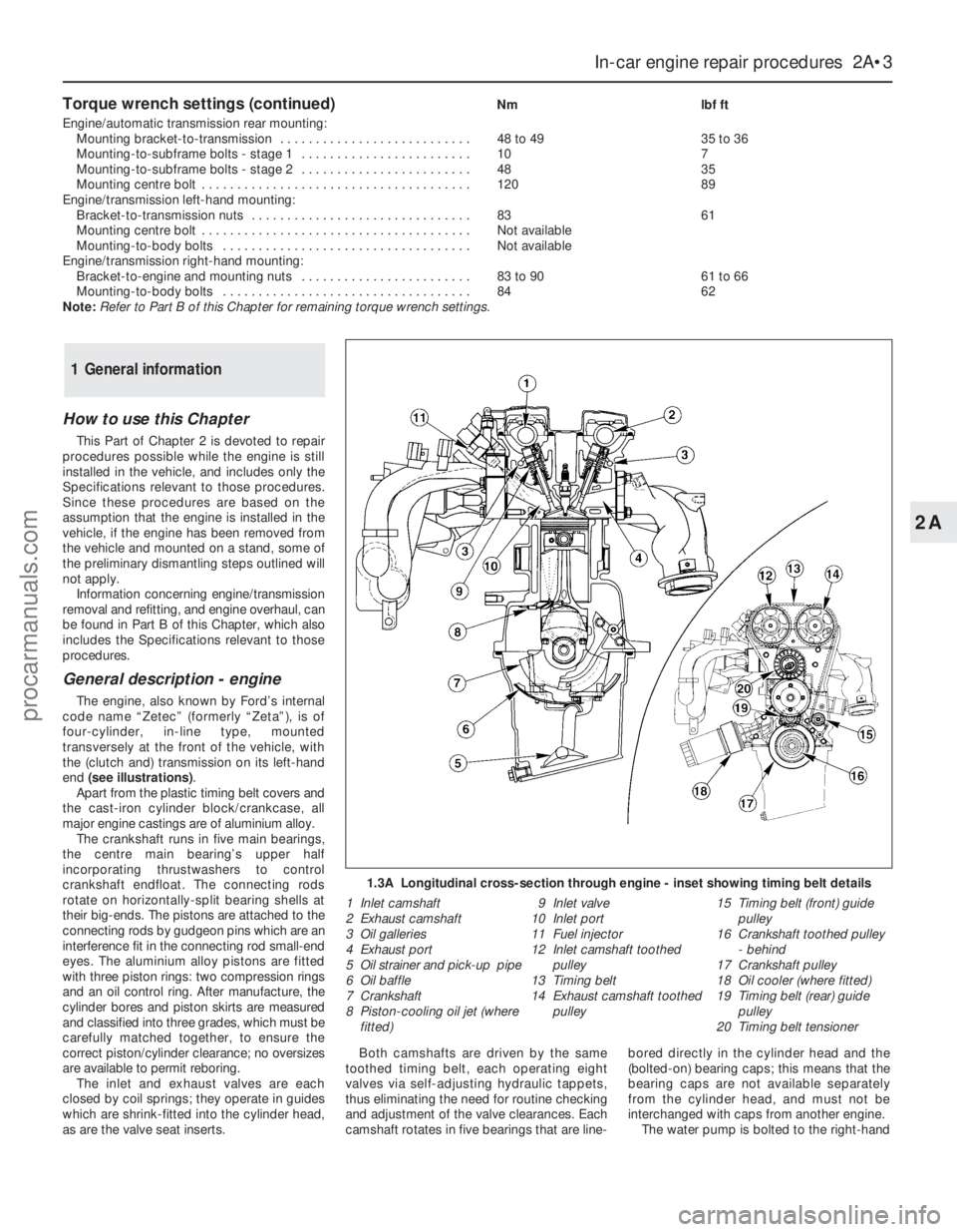
end (see illustrations).
Apart from the plastic timing belt covers and
the cast-iron cylinder block/crankcase, all
major engine castings are of aluminium alloy.
The crankshaft runs in five main bearings,
the centre main bearing’s upper half
incorporating thrustwashers to control
crankshaft endfloat. The connecting rods
rotate on horizontally-split bearing shells at
their big-ends. The pistons are attached to the
connecting rods by gudgeon pins which are an
interference fit in the connecting rod small-end
eyes. The aluminium alloy pistons are fitted
with three piston rings: two compression rings
and an oil control ring. After manufacture, the
cylinder bores and piston skirts are measured
and classified into three grades, which must be
carefully matched together, to ensure the
correct piston/cylinder clearance; no oversizes
are available to permit reboring.
The inlet and exhaust valves are each
closed by coil springs; they operate in guides
which are shrink-fitted into the cylinder head,
as are the valve seat inserts.Both camshafts are driven by the same
toothed timing belt, each operating eight
valves via self-adjusting hydraulic tappets,
thus eliminating the need for routine checking
and adjustment of the valve clearances. Each
camshaft rotates in five bearings that are line-bored directly in the cylinder head and the
(bolted-on) bearing caps; this means that the
bearing caps are not available separately
from the cylinder head, and must not be
interchanged with caps from another engine.
The water pump is bolted to the right-hand
1 General information
1.3A Longitudinal cross-section through engine - inset showing timing belt details
1 Inlet camshaft
2 Exhaust camshaft
3 Oil galleries
4 Exhaust port
5 Oil strainer and pick-up pipe
6 Oil baffle
7 Crankshaft
8 Piston-cooling oil jet (where
fitted)9 Inlet valve
10 Inlet port
11 Fuel injector
12 Inlet camshaft toothed
pulley
13 Timing belt
14 Exhaust camshaft toothed
pulley15 Timing belt (front) guide
pulley
16 Crankshaft toothed pulley
- behind
17 Crankshaft pulley
18 Oil cooler (where fitted)
19 Timing belt (rear) guide
pulley
20 Timing belt tensioner
procarmanuals.com
Page 45 of 279
The cylinder head is provided with two oil
galleries, one on the inlet side and one on the
exhaust, to ensure constant oil supply to the
camshaft bearings and hydraulic tappets. A
retaining valve (inserted into the cylinder
head’s top surface, in the middle, on the inlet
side) prevents these galleries from being
drained when the engine is switched off. The
valve incorporates a ventilation hole in its
upper end, to allow air bubbles to escape
from the system when the engine is restarted.
While the crankshaft and camshaft
bearings and the hydraulic tappets receive a
pressurised supply, the camshaft lobes and
valves are lubricated by splash, as are all
other engine components.
Valve clearances - general
It is necessary for a clearance to exist
between the tip of each valve stem and the
valve operating mechanism, to allow for the
expansion of the various components as the
engine reaches normal operating
temperature.
On most older engine designs, this meant
that the valve clearances (also known as
“tappet” clearances) had to be checked and
adjusted regularly. If the clearances were
allowed to be too slack, the engine would be
very noisy, its power output would suffer, and
its fuel consumption would increase. If the
clearances were allowed to be too tight, the
engine’s power output would be reduced,
and the valves and their seats could be
severely damaged.
The engines covered in this manual,
however, employ hydraulic tappets which use
the lubricating system’s oil pressure
automatically to take up the clearance
between each camshaft lobe and its
respective valve stem. Therefore, there is no
need for regular checking and adjustment of
the valve clearances, but it is essential that
onlygood-quality oil of the recommended
viscosity and specification is used in the
engine, and that this oil is always changed at
the recommended intervals. If this advice is
not followed, the oilways and tappets may
become clogged with particles of dirt, or
deposits of burnt (inferior) engine oil, so that
the system cannot work properly; ultimately,
one or more of the tappets may fail, and
expensive repairs may be required.
On starting the engine from cold, there will
be a slight delay while full oil pressure builds
up in all parts of the engine, especially in the
tappets; the valve components, therefore,
may well “rattle” for about 10 seconds or so,
and then quieten. This is a normal state of
affairs, and is nothing to worry about,
provided that all tappets quieten quickly and
stay quiet.
After the vehicle has been standing for
several days, the valve components may
“rattle” for longer than usual, as nearly all the
oil will have drained away from the engine’s
top end components and bearing surfaces.
While this is only to be expected, care mustbe taken not to damage the engine under
these circumstances - avoid high speed
running until all the tappets are refilled with oil
and operating normally. With the vehicle
stationary, hold the engine at no more than a
fast idle speed (maximum 2000 to 2500 rpm)
for 10 to 15 seconds, or until the noise
ceases. Do not run the engine at more than
3000 rpm until the tappets are fully recharged
with oil and the noise has ceased.
If the valve components are thought to be
noisy, or if a light rattle persists from the top
end after the engine has warmed up to
normal operating temperature, take the
vehicle to a Ford dealer for expert advice.
Depending on the mileage covered and the
usage to which each vehicle has been put,
some vehicles may be noisier than others;
only a good mechanic experienced in these
engines can tell if the noise level is typical for
the vehicle’s mileage, or if a genuine fault
exists. If any tappet’s operation is faulty, it
must be renewed (Section 13).
The following major repair operations can
be accomplished without removing the
engine from the vehicle. However, owners
should note that any operation involving the
removal of the sump requires careful
forethought, depending on the level of skill
and the tools and facilities available; refer to
the relevant text for details.
(a) Compression pressure - testing.
(b) Cylinder head cover - removal and
refitting.
(c) Timing belt covers - removal and refitting.
(d) Timing belt - renewal.
(e) Timing belt tensioner and toothed pulleys
- removal and refitting.
(f) Camshaft oil seals - renewal.
(g) Camshafts and hydraulic tappets -
removal and refitting.
(h) Cylinder head - removal, overhaul and
refitting.
(i) Cylinder head and pistons -
decarbonising.
(j) Sump - removal and refitting.
(k) Crankshaft oil seals - renewal.
(l) Oil pump - removal and refitting.
(m) Piston/connecting rod assemblies -
removal and refitting (but see note below).
(n) Flywheel/driveplate - removal and
refitting.
(o) Engine/transmission mountings - removal
and refitting.
Clean the engine compartment and the
exterior of the engine with some type of
degreaser before any work is done. It will
make the job easier, and will help to keep dirt
out of the internal areas of the engine.
Depending on the components involved, it
may be helpful to remove the bonnet, to
improve access to the engine as repairs are
performed (refer to Chapter 11 if necessary).Cover the wings to prevent damage to the
paint; special covers are available, but an old
bedspread or blanket will also work.
If vacuum, exhaust, oil or coolant leaks
develop, indicating a need for component/
gasket or seal replacement, the repairs can
generally be made with the engine in the
vehicle. The intake and exhaust manifold
gaskets, sump gasket, crankshaft oil seals
and cylinder head gasket are all accessible
with the engine in place.
Exterior components such as the intake
and exhaust manifolds, the sump, the oil
pump, the water pump, the starter motor, the
alternator and the fuel system components
can be removed for repair with the engine in
place.
Since the cylinder head can be removed
without lifting out the engine, camshaft and
valve component servicing can also be
accomplished with the engine in the vehicle,
as can renewal of the timing belt and toothed
pulleys.
In extreme cases caused by a lack of
necessary equipment, repair or renewal of
piston rings, pistons, connecting rods and
big-end bearings is possible with the engine
in the vehicle. However, this practice is not
recommended, because of the cleaning and
preparation work that must be done to the
components involved, and because of the
amount of preliminary dismantling work
required - these operations are therefore
covered in Part B of this Chapter.
1When engine performance is down, or if
misfiring occurs which cannot be attributed to
the ignition or fuel systems, a compression
test can provide diagnostic clues as to the
engine’s condition. If the test is performed
regularly, it can give warning of trouble before
any other symptoms become apparent.
2The engine must be fully warmed-up to
normal operating temperature, the oil level
must be correct, the battery must be fully
charged, and the spark plugs must be
removed. The aid of an assistant will be
required also.
3Disable the ignition system by unplugging
the ignition coil’s electrical connector, and
remove fuse 14 to disconnect the fuel pump.
4Fit a compression tester to the No 1
cylinder spark plug hole - the type of tester
which screws into the plug thread is to be
preferred.
5Have the assistant hold the throttle wide
open and crank the engine on the starter
motor; after one or two revolutions, the
compression pressure should build up to a
maximum figure, and then stabilise. Record
the highest reading obtained.
6Repeat the test on the remaining cylinders,
recording the pressure developed in each.
7At the time of writing, no compression
3 Compression test -
description and interpretation
2 Repair operations possible with
the engine in the vehicle
In-car engine repair procedures 2A•5
2A
procarmanuals.com