key battery FORD MONDEO 1993 Service User Guide
[x] Cancel search | Manufacturer: FORD, Model Year: 1993, Model line: MONDEO, Model: FORD MONDEO 1993Pages: 279, PDF Size: 12.71 MB
Page 191 of 279
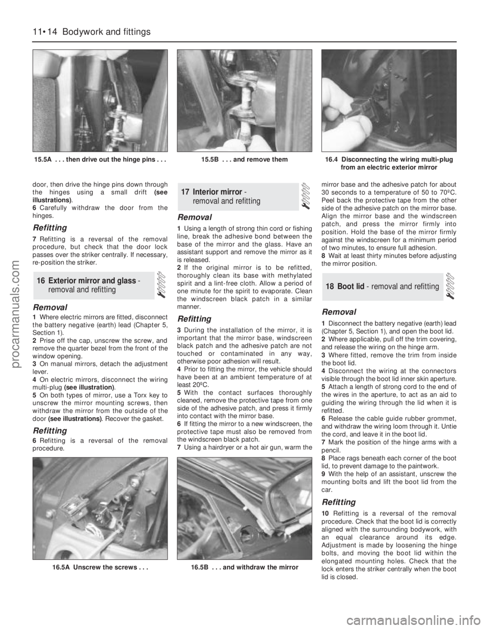
door, then drive the hinge pins down through
the hinges using a small drift (see
illustrations).
6Carefully withdraw the door from the
hinges.
Refitting
7Refitting is a reversal of the removal
procedure, but check that the door lock
passes over the striker centrally. If necessary,
re-position the striker.
Removal
1Where electric mirrors are fitted, disconnect
the battery negative (earth) lead (Chapter 5,
Section 1).
2Prise off the cap, unscrew the screw, and
remove the quarter bezel from the front of the
window opening.
3On manual mirrors, detach the adjustment
lever.
4On electric mirrors, disconnect the wiring
multi-plug (see illustration).
5On both types of mirror, use a Torx key to
unscrew the mirror mounting screws, then
withdraw the mirror from the outside of the
door (see illustrations). Recover the gasket.
Refitting
6Refitting is a reversal of the removal
procedure.
Removal
1Using a length of strong thin cord or fishing
line, break the adhesive bond between the
base of the mirror and the glass. Have an
assistant support and remove the mirror as it
is released.
2If the original mirror is to be refitted,
thoroughly clean its base with methylated
spirit and a lint-free cloth. Allow a period of
one minute for the spirit to evaporate. Clean
the windscreen black patch in a similar
manner.
Refitting
3During the installation of the mirror, it is
important that the mirror base, windscreen
black patch and the adhesive patch are not
touched or contaminated in any way,
otherwise poor adhesion will result.
4Prior to fitting the mirror, the vehicle should
have been at an ambient temperature of at
least 20ºC.
5With the contact surfaces thoroughly
cleaned, remove the protective tape from one
side of the adhesive patch, and press it firmly
into contact with the mirror base.
6If fitting the mirror to a new windscreen, the
protective tape must also be removed from
the windscreen black patch.
7Using a hairdryer or a hot air gun, warm themirror base and the adhesive patch for about
30 seconds to a temperature of 50 to 70ºC.
Peel back the protective tape from the other
side of the adhesive patch on the mirror base.
Align the mirror base and the windscreen
patch, and press the mirror firmly into
position. Hold the base of the mirror firmly
against the windscreen for a minimum period
of two minutes, to ensure full adhesion.
8Wait at least thirty minutes before adjusting
the mirror position.
Removal
1Disconnect the battery negative (earth) lead
(Chapter 5, Section 1), and open the boot lid.
2Where applicable, pull off the trim covering,
and release the wiring on the hinge arm.
3Where fitted, remove the trim from inside
the boot lid.
4Disconnect the wiring at the connectors
visible through the boot lid inner skin aperture.
5Attach a length of strong cord to the end of
the wires in the aperture, to act as an aid to
guiding the wiring through the lid when it is
refitted.
6Release the cable guide rubber grommet,
and withdraw the wiring loom through it. Untie
the cord, and leave it in the boot lid.
7Mark the position of the hinge arms with a
pencil.
8Place rags beneath each corner of the boot
lid, to prevent damage to the paintwork.
9With the help of an assistant, unscrew the
mounting bolts and lift the boot lid from the
car.
Refitting
10Refitting is a reversal of the removal
procedure. Check that the boot lid is correctly
aligned with the surrounding bodywork, with
an equal clearance around its edge.
Adjustment is made by loosening the hinge
bolts, and moving the boot lid within the
elongated mounting holes. Check that the
lock enters the striker centrally when the boot
lid is closed.
18 Boot lid - removal and refitting
17 Interior mirror -
removal and refitting
16 Exterior mirror and glass-
removal and refitting
11•14 Bodywork and fittings
15.5A . . . then drive out the hinge pins . . .15.5B . . . and remove them16.4 Disconnecting the wiring multi-plug
from an electric exterior mirror
16.5A Unscrew the screws . . .16.5B . . . and withdraw the mirror
procarmanuals.com
Page 192 of 279
Removal
Lock barrel
1Disconnect the battery negative (earth) lead
(Chapter 5, Section 1).
2With the boot lid open, remove the luggage
space trim from the right-hand rear corner.
3Remove the screws, and prise out the rear
light trim cover from the guides.
4Release the door-ajar sensor from the clip
near the lock.
5Slide the outer cable from the lock bracket.
Raise the inner cable until it is aligned with the
slot in the barrel lever, and disconnect it.
6Pull out the lock locating spring clip.
7Detach the cable mounting bracket from
the barrel, and remove the barrel.
Lock
8Disconnect the battery negative (earth) lead
(Chapter 5, Section 1).
9With the boot lid open, prise out the clips
and remove the trim from inside the boot lid.
10Release the door-ajar sensor from the clip
near the lock.
11Using a Torx key, unscrew the lock
mounting screws, and withdraw the lock for
access to the cables.
12Disconnect both the inner and outer
cables from the lock bracket.13Prise open the plastic lip, and remove the
central locking control rod.
14Withdraw the lock assembly.
Refitting
Lock barrel and lock
15Refitting is a reversal of the removal
procedure.
Removal
Hatchback
1Disconnect the battery negative (earth) lead
(Chapter 5, Section 1). Open the tailgate.
2The tailgate may be unbolted from the
hinges and the hinges left in position, or the
hinges may be detached from the roof panel
by unscrewing the mounting nuts. In the latter
case, carefully pull down the rear edge of the
headlining for access to the nuts. Take care
not to damage the headlining.
3Remove the parcel shelf left-hand support
bracket as follows. Fold the rear seat
forwards, and disconnect the left-hand seat
pull cable from the bracket and clips.
Unscrew the screws and remove the bracket.
4Pull up the rear seat side bolster, then
carefully remove the side trim from the left-
hand side of the luggage area. On low-series
models, the bolster is retained with a screw.5Separate the tailgate wiring loom multi-
plugs, located on the left-hand side of the
luggage compartment, on top of the wheel
arch.
6Unclip and remove the upper trim panel
from the inside of the tailgate. Also remove
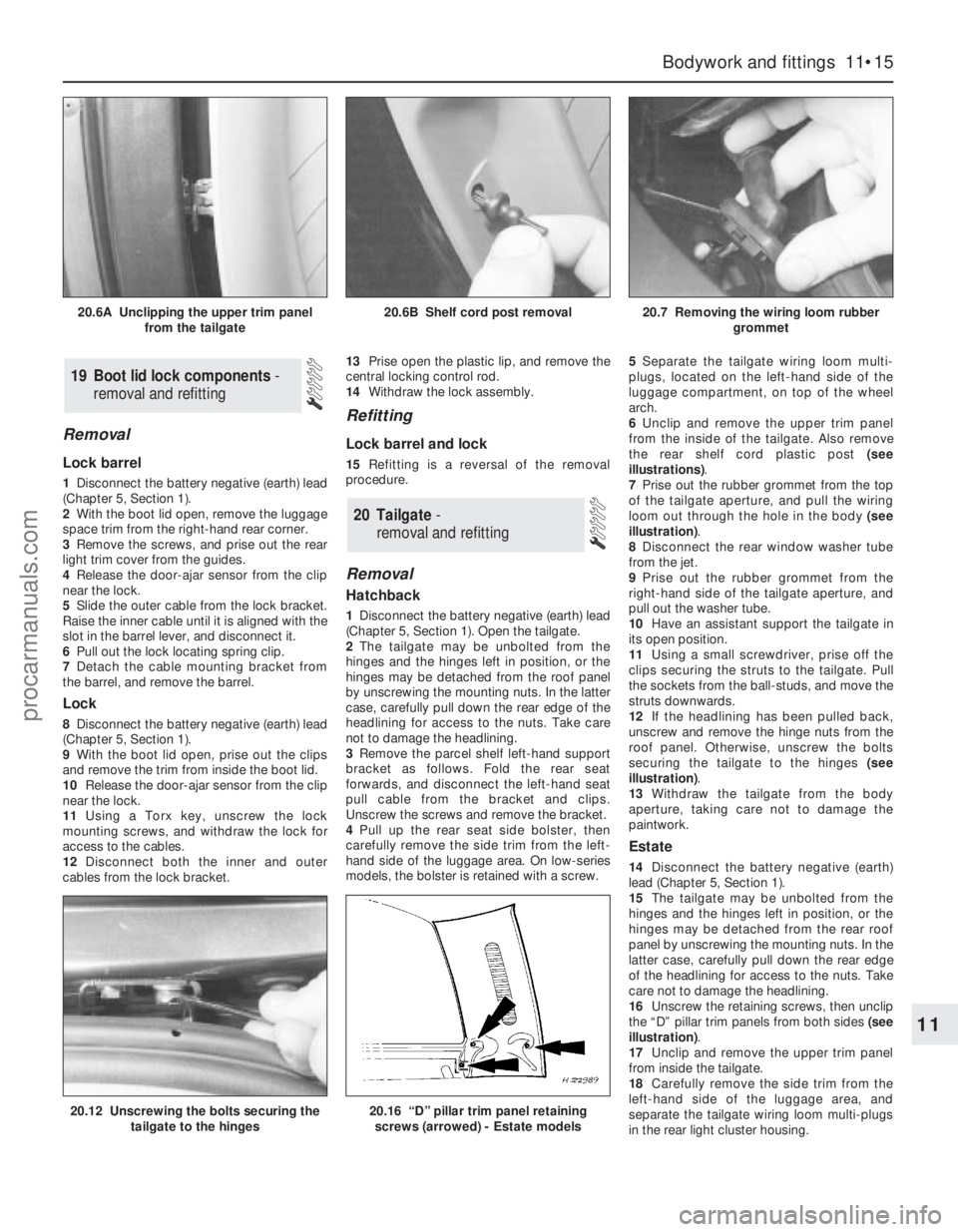
the rear shelf cord plastic post (see
illustrations).
7Prise out the rubber grommet from the top
of the tailgate aperture, and pull the wiring
loom out through the hole in the body (see
illustration).
8Disconnect the rear window washer tube
from the jet.
9Prise out the rubber grommet from the
right-hand side of the tailgate aperture, and
pull out the washer tube.
10Have an assistant support the tailgate in
its open position.
11Using a small screwdriver, prise off the
clips securing the struts to the tailgate. Pull
the sockets from the ball-studs, and move the
struts downwards.
12If the headlining has been pulled back,
unscrew and remove the hinge nuts from the
roof panel. Otherwise, unscrew the bolts
securing the tailgate to the hinges (see
illustration).
13Withdraw the tailgate from the body
aperture, taking care not to damage the
paintwork.
Estate
14Disconnect the battery negative (earth)
lead (Chapter 5, Section 1).
15The tailgate may be unbolted from the
hinges and the hinges left in position, or the
hinges may be detached from the rear roof
panel by unscrewing the mounting nuts. In the
latter case, carefully pull down the rear edge
of the headlining for access to the nuts. Take
care not to damage the headlining.
16Unscrew the retaining screws, then unclip
the “D” pillar trim panels from both sides (see
illustration).
17Unclip and remove the upper trim panel
from inside the tailgate.
18Carefully remove the side trim from the
left-hand side of the luggage area, and
separate the tailgate wiring loom multi-plugs
in the rear light cluster housing.
20 Tailgate -
removal and refitting
19 Boot lid lock components-
removal and refitting
Bodywork and fittings 11•15
11
20.12 Unscrewing the bolts securing the
tailgate to the hinges20.16 “D” pillar trim panel retaining
screws (arrowed) - Estate models
20.6A Unclipping the upper trim panel
from the tailgate20.6B Shelf cord post removal20.7 Removing the wiring loom rubber
grommet
procarmanuals.com
Page 194 of 279
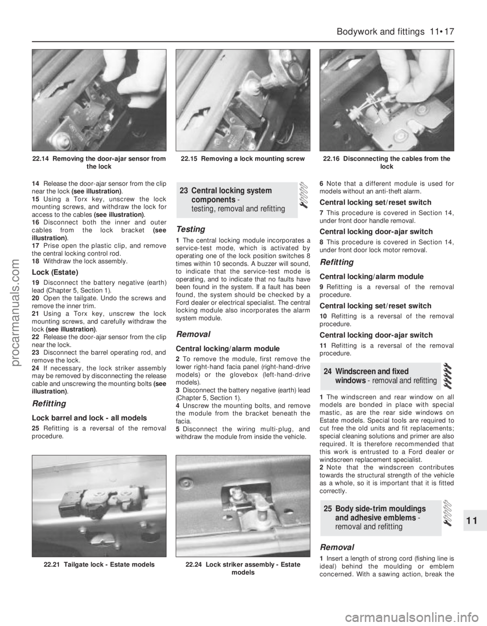
14Release the door-ajar sensor from the clip
near the lock (see illustration).
15Using a Torx key, unscrew the lock
mounting screws, and withdraw the lock for
access to the cables (see illustration).
16Disconnect both the inner and outer
cables from the lock bracket (see
illustration).
17Prise open the plastic clip, and remove
the central locking control rod.
18Withdraw the lock assembly.
Lock (Estate)
19Disconnect the battery negative (earth)
lead (Chapter 5, Section 1).
20Open the tailgate. Undo the screws and
remove the inner trim.
21Using a Torx key, unscrew the lock
mounting screws, and carefully withdraw the
lock (see illustration).
22Release the door-ajar sensor from the clip
near the lock.
23Disconnect the barrel operating rod, and
remove the lock.
24If necessary, the lock striker assembly
may be removed by disconnecting the release
cable and unscrewing the mounting bolts (see
illustration).
Refitting
Lock barrel and lock - all models
25Refitting is a reversal of the removal
procedure.
Testing
1The central locking module incorporates a
service-test mode, which is activated by
operating one of the lock position switches 8
times within 10 seconds. A buzzer will sound,
to indicate that the service-test mode is
operating, and to indicate that no faults have
been found in the system. If a fault has been
found, the system should be checked by a
Ford dealer or electrical specialist. The central
locking module also incorporates the alarm
system module.
Removal
Central locking/alarm module
2To remove the module, first remove the
lower right-hand facia panel (right-hand-drive
models) or the glovebox (left-hand-drive
models).
3Disconnect the battery negative (earth) lead
(Chapter 5, Section 1).
4Unscrew the mounting bolts, and remove
the module from the bracket beneath the
facia.
5Disconnect the wiring multi-plug, and
withdraw the module from inside the vehicle.6Note that a different module is used for
models without an anti-theft alarm.
Central locking set/reset switch
7This procedure is covered in Section 14,
under front door handle removal.
Central locking door-ajar switch
8This procedure is covered in Section 14,
under front door lock motor removal.
Refitting
Central locking/alarm module
9Refitting is a reversal of the removal
procedure.
Central locking set/reset switch
10Refitting is a reversal of the removal
procedure.
Central locking door-ajar switch
11Refitting is a reversal of the removal
procedure.
1The windscreen and rear window on all
models are bonded in place with special
mastic, as are the rear side windows on
Estate models. Special tools are required to
cut free the old units and fit replacements;
special cleaning solutions and primer are also
required. It is therefore recommended that
this work is entrusted to a Ford dealer or
windscreen replacement specialist.
2Note that the windscreen contributes
towards the structural strength of the vehicle
as a whole, so it is important that it is fitted
correctly.
Removal
1Insert a length of strong cord (fishing line is
ideal) behind the moulding or emblem
concerned. With a sawing action, break the
25 Body side-trim mouldings
and adhesive emblems -
removal and refitting
24 Windscreen and fixed
windows - removal and refitting
23 Central locking system
components-
testing, removal and refitting
Bodywork and fittings 11•17
11
22.21 Tailgate lock - Estate models22.24 Lock striker assembly - Estate
models
22.14 Removing the door-ajar sensor from
the lock22.15 Removing a lock mounting screw22.16 Disconnecting the cables from the
lock
procarmanuals.com
Page 195 of 279
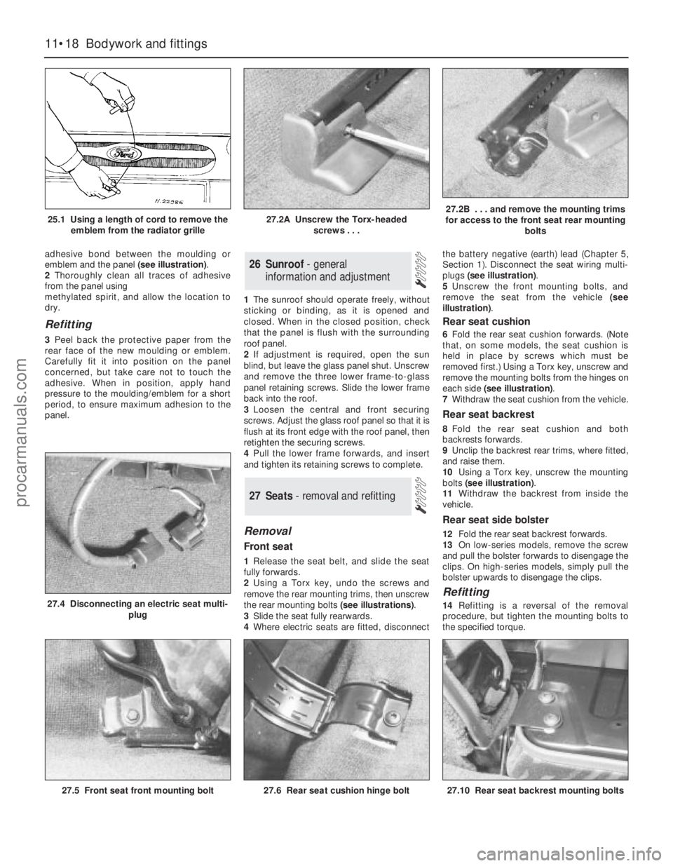
adhesive bond between the moulding or
emblem and the panel (see illustration).
2Thoroughly clean all traces of adhesive
from the panel using
methylated spirit, and allow the location to
dry.
Refitting
3Peel back the protective paper from the
rear face of the new moulding or emblem.
Carefully fit it into position on the panel
concerned, but take care not to touch the
adhesive. When in position, apply hand
pressure to the moulding/emblem for a short
period, to ensure maximum adhesion to the
panel.1The sunroof should operate freely, without
sticking or binding, as it is opened and
closed. When in the closed position, check
that the panel is flush with the surrounding
roof panel.
2If adjustment is required, open the sun
blind, but leave the glass panel shut. Unscrew
and remove the three lower frame-to-glass
panel retaining screws. Slide the lower frame
back into the roof.
3Loosen the central and front securing
screws. Adjust the glass roof panel so that it is
flush at its front edge with the roof panel, then
retighten the securing screws.
4Pull the lower frame forwards, and insert
and tighten its retaining screws to complete.
Removal
Front seat
1Release the seat belt, and slide the seat
fully forwards.
2Using a Torx key, undo the screws and
remove the rear mounting trims, then unscrew
the rear mounting bolts (see illustrations).
3Slide the seat fully rearwards.
4Where electric seats are fitted, disconnectthe battery negative (earth) lead (Chapter 5,
Section 1). Disconnect the seat wiring multi-
plugs (see illustration).
5Unscrew the front mounting bolts, and
remove the seat from the vehicle (see
illustration).
Rear seat cushion
6Fold the rear seat cushion forwards. (Note
that, on some models, the seat cushion is
held in place by screws which must be
removed first.) Using a Torx key, unscrew and
remove the mounting bolts from the hinges on
each side (see illustration).
7Withdraw the seat cushion from the vehicle.
Rear seat backrest
8Fold the rear seat cushion and both
backrests forwards.
9Unclip the backrest rear trims, where fitted,
and raise them.
10Using a Torx key, unscrew the mounting
bolts (see illustration).
11Withdraw the backrest from inside the
vehicle.
Rear seat side bolster
12Fold the rear seat backrest forwards.
13On low-series models, remove the screw
and pull the bolster forwards to disengage the
clips. On high-series models, simply pull the
bolster upwards to disengage the clips.
Refitting
14Refitting is a reversal of the removal
procedure, but tighten the mounting bolts to
the specified torque.
27 Seats - removal and refitting
26 Sunroof - general
information and adjustment
11•18 Bodywork and fittings
25.1 Using a length of cord to remove the
emblem from the radiator grille27.2A Unscrew the Torx-headed
screws . . .27.2B . . . and remove the mounting trims
for access to the front seat rear mounting
bolts
27.5 Front seat front mounting bolt
27.4 Disconnecting an electric seat multi-
plug
27.6 Rear seat cushion hinge bolt27.10 Rear seat backrest mounting bolts
procarmanuals.com
Page 207 of 279
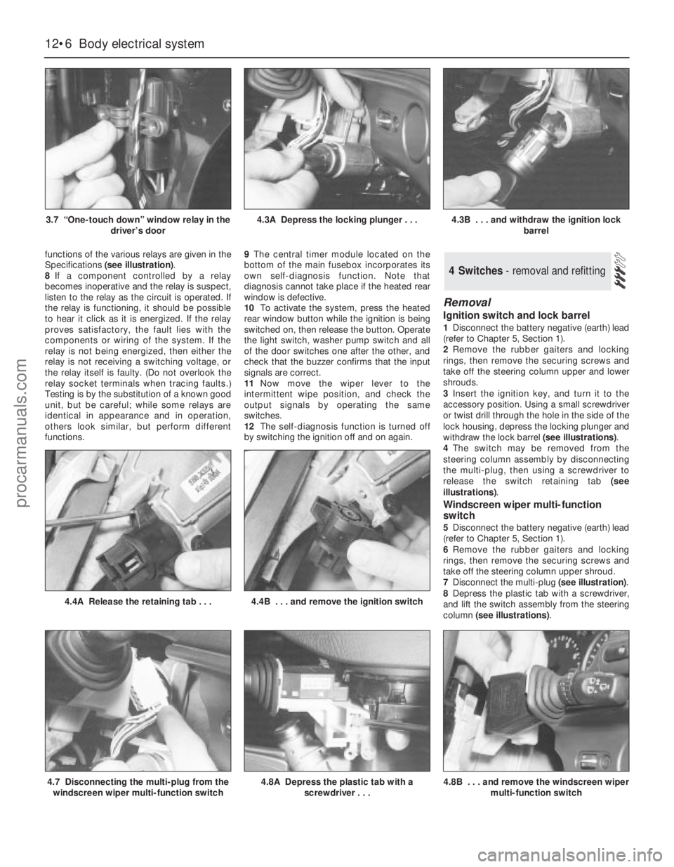
functions of the various relays are given in the
Specifications (see illustration).
8If a component controlled by a relay
becomes inoperative and the relay is suspect,
listen to the relay as the circuit is operated. If
the relay is functioning, it should be possible
to hear it click as it is energized. If the relay
proves satisfactory, the fault lies with the
components or wiring of the system. If the
relay is not being energized, then either the
relay is not receiving a switching voltage, or
the relay itself is faulty. (Do not overlook the
relay socket terminals when tracing faults.)
Testing is by the substitution of a known good
unit, but be careful; while some relays are
identical in appearance and in operation,
others look similar, but perform different
functions.9The central timer module located on the
bottom of the main fusebox incorporates its
own self-diagnosis function. Note that
diagnosis cannot take place if the heated rear
window is defective.
10To activate the system, press the heated
rear window button while the ignition is being
switched on, then release the button. Operate
the light switch, washer pump switch and all
of the door switches one after the other, and
check that the buzzer confirms that the input
signals are correct.
11Now move the wiper lever to the
intermittent wipe position, and check the
output signals by operating the same
switches.
12The self-diagnosis function is turned off
by switching the ignition off and on again.
Removal
Ignition switch and lock barrel
1Disconnect the battery negative (earth) lead
(refer to Chapter 5, Section 1).
2Remove the rubber gaiters and locking
rings, then remove the securing screws and
take off the steering column upper and lower
shrouds.
3Insert the ignition key, and turn it to the
accessory position. Using a small screwdriver
or twist drill through the hole in the side of the
lock housing, depress the locking plunger and
withdraw the lock barrel (see illustrations).
4The switch may be removed from the
steering column assembly by disconnecting
the multi-plug, then using a screwdriver to
release the switch retaining tab (see
illustrations).
Windscreen wiper multi-function
switch
5Disconnect the battery negative (earth) lead
(refer to Chapter 5, Section 1).
6Remove the rubber gaiters and locking
rings, then remove the securing screws and
take off the steering column upper shroud.
7Disconnect the multi-plug (see illustration).
8Depress the plastic tab with a screwdriver,
and lift the switch assembly from the steering
column (see illustrations).
4 Switches - removal and refitting
12•6 Body electrical system
3.7 “One-touch down” window relay in the
driver’s door4.3A Depress the locking plunger . . .4.3B . . . and withdraw the ignition lock
barrel
4.7 Disconnecting the multi-plug from the
windscreen wiper multi-function switch4.8A Depress the plastic tab with a
screwdriver . . .
4.4A Release the retaining tab . . .4.4B . . . and remove the ignition switch
4.8B . . . and remove the windscreen wiper
multi-function switch
procarmanuals.com
Page 222 of 279
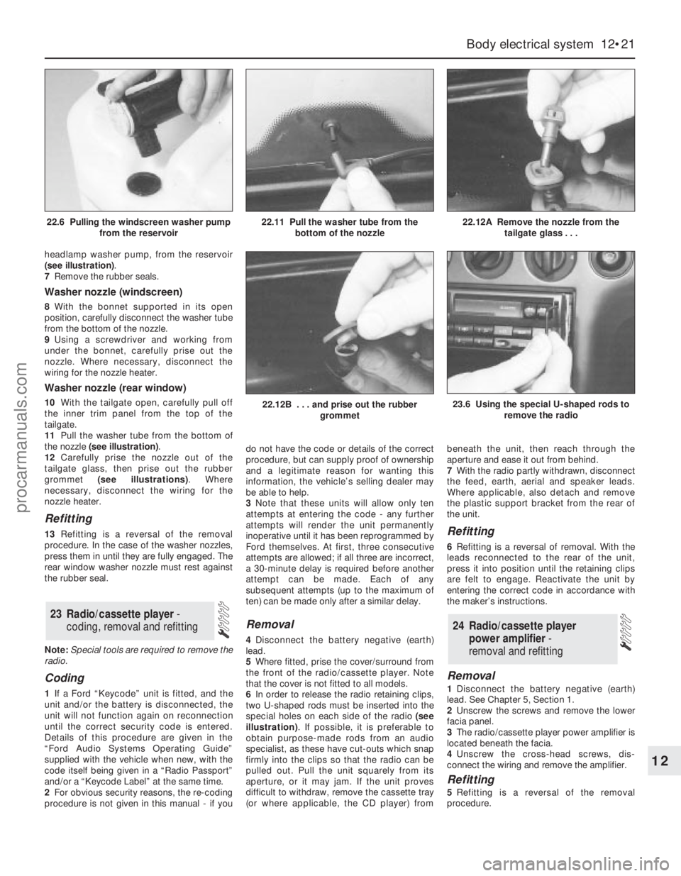
headlamp washer pump, from the reservoir
(see illustration).
7Remove the rubber seals.
Washer nozzle (windscreen)
8With the bonnet supported in its open
position, carefully disconnect the washer tube
from the bottom of the nozzle.
9Using a screwdriver and working from
under the bonnet, carefully prise out the
nozzle. Where necessary, disconnect the
wiring for the nozzle heater.
Washer nozzle (rear window)
10With the tailgate open, carefully pull off
the inner trim panel from the top of the
tailgate.
11Pull the washer tube from the bottom of
the nozzle (see illustration).
12Carefully prise the nozzle out of the
tailgate glass, then prise out the rubber
grommet (see illustrations). Where
necessary, disconnect the wiring for the
nozzle heater.
Refitting
13Refitting is a reversal of the removal
procedure. In the case of the washer nozzles,
press them in until they are fully engaged. The
rear window washer nozzle must rest against
the rubber seal.
Note:Special tools are required to remove the
radio.
Coding
1If a Ford “Keycode” unit is fitted, and the
unit and/or the battery is disconnected, the
unit will not function again on reconnection
until the correct security code is entered.
Details of this procedure are given in the
“Ford Audio Systems Operating Guide”
supplied with the vehicle when new, with the
code itself being given in a “Radio Passport”
and/or a “Keycode Label” at the same time.
2For obvious security reasons, the re-coding
procedure is not given in this manual - if youdo not have the code or details of the correct
procedure, but can supply proof of ownership
and a legitimate reason for wanting this
information, the vehicle’s selling dealer may
be able to help.
3Note that these units will allow only ten
attempts at entering the code - any further
attempts will render the unit permanently
inoperative until it has been reprogrammed by
Ford themselves. At first, three consecutive
attempts are allowed; if all three are incorrect,
a 30-minute delay is required before another
attempt can be made. Each of any
subsequent attempts (up to the maximum of
ten) can be made only after a similar delay.
Removal
4Disconnect the battery negative (earth)
lead.
5Where fitted, prise the cover/surround from
the front of the radio/cassette player. Note
that the cover is not fitted to all models.
6In order to release the radio retaining clips,
two U-shaped rods must be inserted into the
special holes on each side of the radio (see
illustration). If possible, it is preferable to
obtain purpose-made rods from an audio
specialist, as these have cut-outs which snap
firmly into the clips so that the radio can be
pulled out. Pull the unit squarely from its
aperture, or it may jam. If the unit proves
difficult to withdraw, remove the cassette tray
(or where applicable, the CD player) frombeneath the unit, then reach through the
aperture and ease it out from behind.
7With the radio partly withdrawn, disconnect
the feed, earth, aerial and speaker leads.
Where applicable, also detach and remove
the plastic support bracket from the rear of
the unit.
Refitting
6Refitting is a reversal of removal. With the
leads reconnected to the rear of the unit,
press it into position until the retaining clips
are felt to engage. Reactivate the unit by
entering the correct code in accordance with
the maker’s instructions.
Removal
1Disconnect the battery negative (earth)
lead. See Chapter 5, Section 1.
2Unscrew the screws and remove the lower
facia panel.
3The radio/cassette player power amplifier is
located beneath the facia.
4Unscrew the cross-head screws, dis-
connect the wiring and remove the amplifier.
Refitting
5Refitting is a reversal of the removal
procedure.
24 Radio/cassette player
power amplifier -
removal and refitting
23 Radio/cassette player -
coding, removal and refitting
Body electrical system 12•21
12
22.12B . . . and prise out the rubber
grommet23.6 Using the special U-shaped rods to
remove the radio
22.6 Pulling the windscreen washer pump
from the reservoir22.11 Pull the washer tube from the
bottom of the nozzle22.12A Remove the nozzle from the
tailgate glass . . .
procarmanuals.com
Page 272 of 279
REF•13Glossary of Technical Terms
A
ABS (Anti-lock brake system)A system,
usually electronically controlled, that senses
incipient wheel lockup during braking and
relieves hydraulic pressure at wheels that are
about to skid.
Air bag An inflatable bag hidden in the
steering wheel (driver’s side) or the dash or
glovebox (passenger side). In a head-on
collision, the bags inflate, preventing the
driver and front passenger from being thrown
forward into the steering wheel or windscreen.
Air cleanerA metal or plastic housing,
containing a filter element, which removes
dust and dirt from the air being drawn into the
engine.
Air filter elementThe actual filter in an air
cleaner system, usually manufactured from
pleated paper and requiring renewal at regular
intervals.
Allen keyA hexagonal wrench which fits into
a recessed hexagonal hole.
Alligator clipA long-nosed spring-loaded
metal clip with meshing teeth. Used to make
temporary electrical connections.
AlternatorA component in the electrical
system which converts mechanical energy
from a drivebelt into electrical energy to
charge the battery and to operate the starting
system, ignition system and electrical
accessories.
Ampere (amp)A unit of measurement for the
flow of electric current. One amp is the
amount of current produced by one volt
acting through a resistance of one ohm.
Anaerobic sealerA substance used to
prevent bolts and screws from loosening.
Anaerobic means that it does not require
oxygen for activation. The Loctite brand is
widely used.
AntifreezeA substance (usually ethylene
glycol) mixed with water, and added to a
vehicle’s cooling system, to prevent freezing
of the coolant in winter. Antifreeze also
contains chemicals to inhibit corrosion and
the formation of rust and other deposits that
would tend to clog the radiator and coolant
passages and reduce cooling efficiency.
Anti-seize compoundA coating that
reduces the risk of seizing on fasteners that
are subjected to high temperatures, such as
exhaust manifold bolts and nuts.
AsbestosA natural fibrous mineral with great
heat resistance, commonly used in the
composition of brake friction materials.Asbestos is a health hazard and the dust
created by brake systems should never be
inhaled or ingested.
AxleA shaft on which a wheel revolves, or
which revolves with a wheel. Also, a solid
beam that connects the two wheels at one
end of the vehicle. An axle which also
transmits power to the wheels is known as a
live axle.
AxleshaftA single rotating shaft, on either
side of the differential, which delivers power
from the final drive assembly to the drive
wheels. Also called a driveshaft or a halfshaft.
BBall bearingAn anti-friction bearing
consisting of a hardened inner and outer race
with hardened steel balls between two races.
BearingThe curved surface on a shaft or in a
bore, or the part assembled into either, that
permits relative motion between them with
minimum wear and friction.
Big-end bearingThe bearing in the end of
the connecting rod that’s attached to the
crankshaft.
Bleed nippleA valve on a brake wheel
cylinder, caliper or other hydraulic component
that is opened to purge the hydraulic system
of air. Also called a bleed screw.
Brake bleedingProcedure for removing air
from lines of a hydraulic brake system.
Brake discThe component of a disc brake
that rotates with the wheels.Brake drumThe component of a drum brake
that rotates with the wheels.
Brake liningsThe friction material which
contacts the brake disc or drum to retard the
vehicle’s speed. The linings are bonded or
riveted to the brake pads or shoes.
Brake padsThe replaceable friction pads
that pinch the brake disc when the brakes are
applied. Brake pads consist of a friction
material bonded or riveted to a rigid backing
plate.
Brake shoeThe crescent-shaped carrier to
which the brake linings are mounted and
which forces the lining against the rotating
drum during braking.
Braking systemsFor more information on
braking systems, consult the Haynes
Automotive Brake Manual.
Breaker barA long socket wrench handle
providing greater leverage.
BulkheadThe insulated partition between
the engine and the passenger compartment.
CCaliperThe non-rotating part of a disc-brake
assembly that straddles the disc and carries
the brake pads. The caliper also contains the
hydraulic components that cause the pads to
pinch the disc when the brakes are applied. A
caliper is also a measuring tool that can be set
to measure inside or outside dimensions of an
object.
CamshaftA rotating shaft on which a series
of cam lobes operate the valve mechanisms.
The camshaft may be driven by gears, by
sprockets and chain or by sprockets and a
belt.
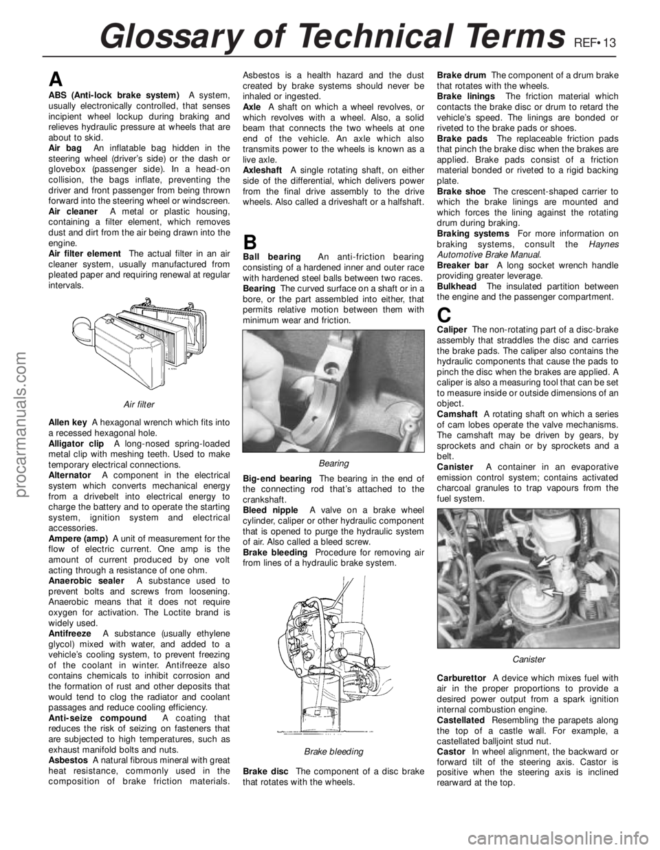
CanisterA container in an evaporative
emission control system; contains activated
charcoal granules to trap vapours from the
fuel system.
CarburettorA device which mixes fuel with
air in the proper proportions to provide a
desired power output from a spark ignition
internal combustion engine.
CastellatedResembling the parapets along
the top of a castle wall. For example, a
castellated balljoint stud nut.
CastorIn wheel alignment, the backward or
forward tilt of the steering axis. Castor is
positive when the steering axis is inclined
rearward at the top.
Canister
Brake bleeding
Bearing
Air filter
procarmanuals.com