engine coolant FORD MONDEO 1993 Service Workshop Manual
[x] Cancel search | Manufacturer: FORD, Model Year: 1993, Model line: MONDEO, Model: FORD MONDEO 1993Pages: 279, PDF Size: 12.71 MB
Page 219 of 279
the specified mileage (or time) since the last
service has been reached.
4To reset the service interval system and
turn off the light, a switch inside the glovebox
must be depressed for a minimum of 4
seconds with the ignition switched on. This
should be carried out by a Ford dealer if the
vehicle is still in the warranty period.
Component renewal
5The following paragraphs describe brief
removal procedures for the auxiliary warning
system components. Disconnect the battery
negative (earth) lead before commencing
work (refer to Chapter 5, Section 1). Refitting
procedures are a reversal of removal.
Display warning bulb
6Remove the control assembly.
7Prise off the cover, and pull out the relevant
bulb and bulbholder.
Low air temperature warning sender
unit
8Remove the front bumper.
9Unclip the sender unit and disconnect the
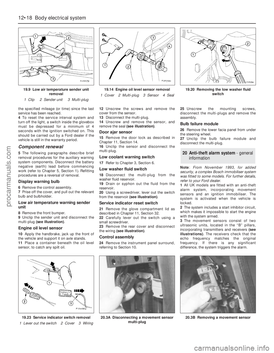
multi-plug (see illustration).
Engine oil level sensor
10Apply the handbrake, jack up the front of
the vehicle and support it on axle stands.
11Place a container beneath the oil level
sensor, to catch any spilt oil.12Unscrew the screws and remove the
cover from the sensor.
13Disconnect the multi-plug.
14Unscrew and remove the sensor, and
remove the seal (see illustration).
Door ajar sensor
15Remove the door lock as described in
Chapter 11, Section 14.
16Unclip the sensor and disconnect the
multi-plug.
Low coolant warning switch
17Refer to Chapter 3, Section 6.
Low washer fluid switch
18Disconnect the multi-plug from the
washer fluid reservoir.
19Drain or syphon out the fluid from the
reservoir.
20Using a screwdriver, lever out the switch
from the reservoir (see illustration).
Service indicator reset switch
21Remove the glove compartment lid as
described in Chapter 11, Section 32.
22Carefully lever out the switch using a
small screwdriver.
23Remove the rear cover and disconnect
the wiring (see illustration).
Control assembly
24Remove the instrument panel surround,
referring to Section 10.25Unscrew the mounting screws,
disconnect the multi-plugs and remove the
assembly.
Bulb failure module
26Remove the lower facia panel from under
the steering wheel.
27Unclip the bulb failure module and
disconnect the multi-plug.
Note: From November 1993, for added
security, a complex Bosch immobiliser system
was fitted to some models. For further details,
refer to your Ford dealer.
1All UK models are fitted with an anti-theft
alarm system, incorporating movement
sensors and an ignition immobiliser. The
system is activated when the vehicle is
locked.
2The system includes a start inhibitor circuit,
which makes it impossible to start the engine
with the system armed.
3The movement sensors consist of two
ultrasonic units, located in the “B” pillars,
incorporating transmitters and receivers (see
illustrations). The receivers check that the
echo frequency matches the original
frequency. If there is any significant
difference, the system triggers the alarm.
20 Anti-theft alarm system- general
information
12•18 Body electrical system
19.9 Low air temperature sender unit
removal
1 Clip 2 Sender unit 3 Multi-plug19.14 Engine oil level sensor removal
1 Cover 2 Multi-plug 3 Sensor 4 Seal19.20 Removing the low washer fluid
switch
19.23 Service indicator switch removal
1 Lever out the switch 2 Cover 3 Wiring20.3A Disconnecting a movement sensor
multi-plug20.3B Removing a movement sensor
procarmanuals.com
Page 263 of 279
REF•4
Whenever servicing, repair or overhaul work
is carried out on the car or its components, it
is necessary to observe the following
procedures and instructions. This will assist in
carrying out the operation efficiently and to a
professional standard of workmanship.
Joint mating faces and gaskets
When separating components at their
mating faces, never insert screwdrivers or
similar implements into the joint between the
faces in order to prise them apart. This can
cause severe damage which results in oil
leaks, coolant leaks, etc upon reassembly.
Separation is usually achieved by tapping
along the joint with a soft-faced hammer in
order to break the seal. However, note that
this method may not be suitable where
dowels are used for component location.
Where a gasket is used between the mating
faces of two components, ensure that it is
renewed on reassembly, and fit it dry unless
otherwise stated in the repair procedure.
Make sure that the mating faces are clean and
dry, with all traces of old gasket removed.
When cleaning a joint face, use a tool which is
not likely to score or damage the face, and
remove any burrs or nicks with an oilstone or
fine file.
Make sure that tapped holes are cleaned
with a pipe cleaner, and keep them free of
jointing compound, if this is being used,
unless specifically instructed otherwise.
Ensure that all orifices, channels or pipes
are clear, and blow through them, preferably
using compressed air.
Oil seals
Oil seals can be removed by levering them
out with a wide flat-bladed screwdriver or
similar implement. Alternatively, a number of
self-tapping screws may be screwed into the
seal, and these used as a purchase for pliers
or some similar device in order to pull the seal
free.
Whenever an oil seal is removed from its
working location, either individually or as part
of an assembly, it should be renewed.
The very fine sealing lip of the seal is easily
damaged, and will not seal if the surface it
contacts is not completely clean and free from
scratches, nicks or grooves.
Protect the lips of the seal from any surface
which may damage them in the course of
fitting. Use tape or a conical sleeve where
possible. Lubricate the seal lips with oil before
fitting and, on dual-lipped seals, fill the space
between the lips with grease.
Unless otherwise stated, oil seals must be
fitted with their sealing lips toward the
lubricant to be sealed.
Use a tubular drift or block of wood of the
appropriate size to install the seal and, if the
seal housing is shouldered, drive the seal
down to the shoulder. If the seal housing is
unshouldered, the seal should be fitted with
its face flush with the housing top face (unless
otherwise instructed).
Screw threads and fastenings
Seized nuts, bolts and screws are quite a
common occurrence where corrosion has set
in, and the use of penetrating oil or releasing
fluid will often overcome this problem if the
offending item is soaked for a while before
attempting to release it. The use of an impact
driver may also provide a means of releasing
such stubborn fastening devices, when used
in conjunction with the appropriate
screwdriver bit or socket. If none of these
methods works, it may be necessary to resort
to the careful application of heat, or the use of
a hacksaw or nut splitter device.
Studs are usually removed by locking two
nuts together on the threaded part, and then
using a spanner on the lower nut to unscrew
the stud. Studs or bolts which have broken off
below the surface of the component in which
they are mounted can sometimes be removed
using a proprietary stud extractor. Always
ensure that a blind tapped hole is completely
free from oil, grease, water or other fluid
before installing the bolt or stud. Failure to do
this could cause the housing to crack due to
the hydraulic action of the bolt or stud as it is
screwed in.
When tightening a castellated nut to accept
a split pin, tighten the nut to the specified
torque, where applicable, and then tighten
further to the next split pin hole. Never slacken
the nut to align the split pin hole, unless stated
in the repair procedure.
When checking or retightening a nut or bolt
to a specified torque setting, slacken the nut
or bolt by a quarter of a turn, and then
retighten to the specified setting. However,
this should not be attempted where angular
tightening has been used.
For some screw fastenings, notably cylinder
head bolts or nuts, torque wrench settings are
no longer specified for the latter stages of
tightening, “angle-tightening” being called up
instead. Typically, a fairly low torque wrench
setting will be applied to the bolts/nuts in
the correct sequence, followed by one or
more stages of tightening through specified
angles.
Locknuts, locktabs and washers
Any fastening which will rotate against a
component or housing in the course of
tightening should always have a washer
between it and the relevant component or
housing.
Spring or split washers should always be
renewed when they are used to lock a critical
component such as a big-end bearing
retaining bolt or nut. Locktabs which are
folded over to retain a nut or bolt should
always be renewed.
Self-locking nuts can be re-used in non-
critical areas, providing resistance can be felt
when the locking portion passes over the bolt
or stud thread. However, it should be noted
that self-locking stiffnuts tend to lose theireffectiveness after long periods of use, and in
such cases should be renewed as a matter of
course.
Split pins must always be replaced with
new ones of the correct size for the hole.
When thread-locking compound is found
on the threads of a fastener which is to be re-
used, it should be cleaned off with a wire
brush and solvent, and fresh compound
applied on reassembly.
Special tools
Some repair procedures in this manual
entail the use of special tools such as a press,
two or three-legged pullers, spring
compressors, etc. Wherever possible, suitable
readily-available alternatives to the
manufacturer’s special tools are described,
and are shown in use. Unless you are highly-
skilled and have a thorough understanding of
the procedures described, never attempt to
bypass the use of any special tool when the
procedure described specifies its use. Not
only is there a very great risk of personal
injury, but expensive damage could be
caused to the components involved.
Environmental considerations
When disposing of used engine oil, brake
fluid, antifreeze, etc, give due consideration to
any detrimental environmental effects. Do not,
for instance, pour any of the above liquids
down drains into the general sewage system,
or onto the ground to soak away. Many local
council refuse tips provide a facility for waste
oil disposal, as do some garages. If none of
these facilities are available, consult your local
Environmental Health Department for further
advice.
With the universal tightening-up of
legislation regarding the emission of
environmentally-harmful substances from
motor vehicles, most current vehicles have
tamperproof devices fitted to the main
adjustment points of the fuel system. These
devices are primarily designed to prevent
unqualified persons from adjusting the fuel/air
mixture, with the chance of a consequent
increase in toxic emissions. If such devices
are encountered during servicing or overhaul,
they should, wherever possible, be renewed
or refitted in accordance with the vehicle
manufacturer’s requirements or current
legislation.
Note: It is
antisocial and
illegal to dump
oil down the
drain. To find
the location of
your local oil
recycling
bank, call this
number free.
General Repair Procedures
procarmanuals.com
Page 265 of 279
REF•6Fault Finding
Engine 1
m mEngine backfires
m mEngine difficult to start when cold
m mEngine difficult to start when hot
m mEngine fails to rotate when attempting to start
m mEngine hesitates on acceleration
m mEngine idles erratically
m mEngine lacks power
m mEngine misfires at idle speed
m mEngine misfires throughout the driving speed range
m mEngine noises
m mEngine rotates but will not start
m mEngine runs-on after switching off
m mEngine stalls
m mEngine starts but stops immediately
m mOil pressure warning light illuminated with engine running
m mStarter motor noisy or excessively-rough in engagement
Cooling system 2
m
mCorrosion
m mExternal coolant leakage
m mInternal coolant leakage
m mOvercooling
m mOverheating
Fuel and exhaust systems 3
m
mExcessive fuel consumption
m mExcessive noise or fumes from exhaust system
m mFuel leakage and/or fuel odour
Clutch 4
m
mClutch fails to disengage (unable to select gears)
m mClutch slips (engine speed increases with no increase
in vehicle speed)
m mJudder as clutch is engaged
m mNoise when depressing or releasing clutch pedal
m mPedal travels to floor - no pressure or very little resistance
Manual transmission 5
m
mJumps out of gear
m mLubricant leaks
m mNoisy in neutral with engine running
m mNoisy in one particular gear
m mVibration
Automatic transmission 6
m
mEngine will not start in any gear, or starts in gears
other than Park or Neutral
m mFluid leakage
m mGeneral gear selection problems
m mTransmission fluid brown, or has burned smell
m mTransmission slips, shifts roughly, is noisy, or
has no drive in forward or reverse gears
m mTransmission will not downshift (kickdown) with
accelerator fully depressed
Driveshafts 7
m mClicking or knocking noise on turns (at slow speed on full-lock)
m mVibration when accelerating or decelerating
Braking system 8
m
mBrake pedal feels spongy when depressed
m mBrakes binding
m mExcessive brake pedal effort required to stop vehicle
m mExcessive brake pedal travel
m mJudder felt through brake pedal or steering wheel when braking
m mNoise (grinding or high-pitched squeal) when brakes applied
m mRear wheels locking under normal braking
m mVehicle pulls to one side under braking
Suspension and steering systems 9
m
mExcessive pitching and/or rolling around corners, or during
braking
m mExcessive play in steering
m mExcessively-stiff steering
m mLack of power assistance
m mTyre wear excessive
m mVehicle pulls to one side
m mWandering or general instability
m mWheel wobble and vibration
Electrical system 10
m
mBattery will not hold a charge for more than a few days
m mCentral locking system inoperative, or unsatisfactory in operation
m mElectric windows inoperative, or unsatisfactory in operation
m mHorn inoperative, or unsatisfactory in operation
m mIgnition warning light fails to come on
m mIgnition warning light remains illuminated with engine running
m mInstrument readings inaccurate or erratic
m mLights inoperative
m mWindscreen/tailgate washers inoperative, or unsatisfactory in
operation
m mWindscreen/tailgate wipers inoperative, or unsatisfactory in
operation
procarmanuals.com
Page 267 of 279
Engine misfires throughout the driving speed range
m mFuel filter choked (Chapter 1).
m mFuel pump faulty or delivery pressure low (Chapter 4).
m mFuel tank vent blocked or fuel pipes restricted (Chapter 4).
m mVacuum leak at the inlet manifold or associated hoses (Chap-
ters 1, 4 and 6).
m mWorn, faulty or incorrectly-gapped spark plugs (Chapter 1).
m mFaulty spark plug HT leads (Chapter 1).
m mFaulty ignition coil (Chapter 5).
m mEngine management system fault (Chapters 1, 4, 5 and 6)
m mUneven or low cylinder compressions (Chapter 2, Part A).
Engine hesitates on acceleration
m
mWorn, faulty or incorrectly-gapped spark plugs (Chapter 1).
m mEngine management system fault (Chapters 1, 4, 5 and 6).
m mVacuum leak at the inlet manifold or associated hoses (Chap-
ters 1, 4 and 6).
Engine stalls
m mIdle speed control valve faulty (Chapter 4).
m mEngine management system fault (Chapters 1, 4, 5 and 6).
m mVacuum leak at the inlet manifold or associated hoses (Chap-
ters 1, 4 and 6).
m mFuel filter choked (Chapter 1).
m mFuel pump faulty or delivery pressure low (Chapter 4).
m mFuel tank vent blocked or fuel pipes restricted (Chapter 4).
Engine lacks power
m
mIncorrect ignition timing (Chapters 5 and 6).
m mEngine management system fault (Chapters 1, 4, 5 and 6).
m mTiming belt incorrectly fitted or incorrectly tensioned (Chapter 2,
Part A).
m mFuel filter choked (Chapter 1).
m mFuel pump faulty or delivery pressure low (Chapter 4).
m mUneven or low cylinder compressions (Chapter 2, Part A).
m mWorn, faulty or incorrectly-gapped spark plugs (Chapter 1).
m mVacuum leak at the inlet manifold or associated hoses (Chap-
ters 1, 4 and 6).
m mBrakes binding (Chapters 1 and 9).
m mClutch slipping (Chapter 8).
m mAutomatic transmission fluid level incorrect (Chapter 1).
Engine runs-on after switching off
m
mIdle speed excessively high (Chapters 4 and 6).
m mEngine management system fault (Chapters 1, 4, 5 and 6).
m mExcessive carbon build-up in engine (Chapter 2, Part A).
m mHigh engine operating temperature (Chapter 3).
Engine backfires
m
mIgnition timing incorrect (Chapters 5 and 6).
m mEngine management system fault (Chapters 1, 4, 5 and 6).
m mTiming belt incorrectly fitted or incorrectly tensioned (Chapter 2,
Part A).
m mVacuum leak at the inlet manifold or associated hoses (Chap-
ters 1, 4 and 6).
Oil pressure warning light illuminated with engine
running
m mLow oil level or incorrect oil grade (Chapter 1).
m mFaulty oil pressure warning light switch (Chapter 2, Part A).
m mWorn engine bearings and/or oil pump (Chapter 2).
m mHigh engine operating temperature (Chapter 3).
m mOil pressure relief valve defective (Chapter 2, Part A).
m mOil pick-up strainer clogged (Chapter 2, Part A).
Engine noises
Pre-ignition (pinking) or knocking during acceleration or under
load
m mIgnition timing incorrect (Chapters 5 and 6).
m mIncorrect grade of fuel (Chapter 4).
m mVacuum leak at the inlet manifold or associated hoses (Chap-
ters 1, 4 and 6).
m mExcessive carbon build-up in engine (Chapter 2, Part A).
Whistling or wheezing noises
m mLeaking inlet manifold gasket (Chapter 2, Part A).
m mLeaking exhaust manifold gasket or downpipe-to-manifold joint
(Chapters 1, 2 Part A, and 4).
m mLeaking vacuum hose (Chapters 1, 4, 6 and 9).
m mBlowing cylinder head gasket (Chapter 2, Part A).
Tapping or rattling noises
m mFaulty hydraulic tappet(s) (Chapter 2, Part A).
m mWorn valve gear or camshaft (Chapter 2, Part A).
m mWorn timing belt or tensioner (Chapter 2, Part A).
m mAncillary component fault (water pump, alternator, etc) (Chap-
ters 3 and 5).
Knocking or thumping noises
m mWorn big-end bearings (regular heavy knocking, perhaps less
under load) (Chapter 2, Part B).
m mWorn main bearings (rumbling and knocking, perhaps worsening
under load) (Chapter 2, Part B).
m mPiston slap (most noticeable when cold) (Chapter 2, Part B).
m mAncillary component fault (water pump, alternator, etc) (Chap-
ters 3 and 5).
REF•8Fault Finding
2 Cooling system
Overheating
m mInsufficient coolant in system (Chapter 1).
m mThermostat faulty (Chapter 3).
m mRadiator core blocked or grille restricted (Chapter 3).
m mRadiator electric cooling fan(s) or coolant temperature sensor faulty
(Chapter 3).
m mEngine management system fault (Chapters 1, 4, 5 and 6).
m mPressure cap faulty (Chapter 3).
m mAuxiliary drivebelt worn or slipping (Chapter 1).
m mIgnition timing incorrect (Chapters 5 and 6).
m mInaccurate coolant temperature gauge sender (Chapter 3).
m mAir-lock in cooling system (Chapter 1).
Overcooling
m
mThermostat faulty (Chapter 3).
m mInaccurate coolant temperature gauge sender (Chapter 3).
External coolant leakage
m
mDeteriorated or damaged hoses or hose clips (Chapter 1).
m mRadiator core or heater matrix leaking (Chapter 3).
m mPressure cap faulty (Chapter 3).
m mWater pump seal leaking (Chapter 3).
m mBoiling due to overheating (Chapter 3).
m mCore plug leaking (Chapter 2, Part B).
procarmanuals.com
Page 268 of 279
REF•9
Excessive fuel consumption
m mUnsympathetic driving style, or adverse conditions.
m mAir filter element dirty or clogged (Chapter 1).
m mEngine management system fault (Chapters 1, 4, 5 and 6).
m mIgnition timing incorrect (Chapters 5 and 6).
m mTyres under-inflated (Chapter 1).
Fuel leakage and/or fuel odour
m
mDamaged or corroded fuel tank, pipes or connections (Chapter 1).
m mCharcoal canister and/or connecting pipes leaking (Chapter 6).
Excessive noise or fumes from exhaust system
m
mLeaking exhaust system or manifold joints (Chapters 1, 2 Part A,
and 4).
m mLeaking, corroded or damaged silencers or pipe (Chapter 1).
m mBroken mountings, causing body or suspension contact (Chap-
ters 1 and 4).
Fault Finding
3 Fuel and exhaust system
Noisy in neutral with engine running
m mInput shaft bearings worn (noise apparent with clutch pedal
released, but not when depressed) (Chapter 7, Part A).*
m mClutch release bearing worn (noise apparent with clutch pedal
depressed, possibly less when released) (Chapter 8).
Noisy in one particular gear
m mWorn, damaged or chipped gear teeth (Chapter 7, Part A).*
Difficulty engaging gears
m
mClutch fault (Chapter 8).
m mWorn or damaged gear linkage (Chapter 7, Part A).
m mIncorrectly-adjusted gear linkage (Chapter 7, Part A).
m mWorn synchroniser assemblies (Chapter 7, Part A).*
Vibration
m
mLack of oil (Chapter 1).
m mWorn bearings (Chapter 7, Part A).*
Jumps out of gear
m
mWorn or damaged gear linkage (Chapter 7, Part A).
m mIncorrectly-adjusted gear linkage (Chapter 7, Part A).
m mWorn synchroniser assemblies (Chapter 7, Part A).*
m mWorn selector forks (Chapter 7, Part A).*
Lubricant leaks
m
mLeaking differential side gear oil seal (Chapter 7, Part A).
m mLeaking housing joint (Chapter 7, Part A).*
m mLeaking input shaft oil seal (Chapter 7, Part A).*
m mLeaking selector shaft oil seal (Chapter 7, Part A).
m mLeaking speedometer drive pinion O-ring (Chapter 7, Part A).
* Although the corrective action necessary to remedy the symptoms
described is beyond the scope of the home mechanic, the above
information should be helpful in isolating the cause of the condition, so
that the owner can communicate clearly with a professional mechanic.
4 Clutch
5 Manual transmission
Pedal travels to floor - no pressure or very little
resistance
m mBroken clutch cable (Chapter 8).
m mIncorrect clutch adjustment (Chapter 8).
m mBroken clutch release bearing or fork (Chapter 8).
m mBroken diaphragm spring in clutch pressure plate (Chapter 8).
Clutch fails to disengage (unable to select gears)
m
mIncorrect clutch adjustment (Chapter 8).
m mClutch disc sticking on transmission input shaft splines (Chapter 8).
m mClutch disc sticking to flywheel or pressure plate (Chapter 8).
m mFaulty pressure plate assembly (Chapter 8).
m mClutch release mechanism worn or incorrectly assembled (Chapter 8).
Clutch slips (engine speed increases with no
increase in vehicle speed)
m mIncorrect clutch adjustment (Chapter 8).
m mClutch disc linings excessively worn (Chapter 8).m mClutch disc linings contaminated with oil or grease (Chapter 8).
m mFaulty pressure plate or weak diaphragm spring (Chapter 8).
Judder as clutch is engaged
m
mClutch disc linings contaminated with oil or grease (Chapter 8).
m mClutch disc linings excessively worn (Chapter 8).
m mClutch cable sticking or frayed (Chapter 8).
m mFaulty or distorted pressure plate or diaphragm spring (Chapter 8).
m mWorn or loose engine/transmission mountings (Chapter 2, Part A).
m mClutch disc hub or transmission input shaft splines worn (Chap-
ter 8).
Noise when depressing or releasing clutch pedal
m mWorn clutch release bearing (Chapter 8).
m mWorn or dry clutch pedal bushes (Chapter 8).
m mFaulty pressure plate assembly (Chapter 8).
m mPressure plate diaphragm spring broken (Chapter 8).
m mBroken clutch disc cushioning springs (Chapter 8).
Internal coolant leakage
m
mLeaking cylinder head gasket (Chapter 2, Part A).
m mCracked cylinder head or cylinder bore (Chapter 2, Part B).
Corrosion
m
mInfrequent draining and flushing (Chapter 1).
m mIncorrect antifreeze mixture, or inappropriate antifreeze type
(Chapter 1).
procarmanuals.com
Page 272 of 279
REF•13Glossary of Technical Terms
A
ABS (Anti-lock brake system)A system,
usually electronically controlled, that senses
incipient wheel lockup during braking and
relieves hydraulic pressure at wheels that are
about to skid.
Air bag An inflatable bag hidden in the
steering wheel (driver’s side) or the dash or
glovebox (passenger side). In a head-on
collision, the bags inflate, preventing the
driver and front passenger from being thrown
forward into the steering wheel or windscreen.
Air cleanerA metal or plastic housing,
containing a filter element, which removes
dust and dirt from the air being drawn into the
engine.
Air filter elementThe actual filter in an air
cleaner system, usually manufactured from
pleated paper and requiring renewal at regular
intervals.
Allen keyA hexagonal wrench which fits into
a recessed hexagonal hole.
Alligator clipA long-nosed spring-loaded
metal clip with meshing teeth. Used to make
temporary electrical connections.
AlternatorA component in the electrical
system which converts mechanical energy
from a drivebelt into electrical energy to
charge the battery and to operate the starting
system, ignition system and electrical
accessories.
Ampere (amp)A unit of measurement for the
flow of electric current. One amp is the
amount of current produced by one volt
acting through a resistance of one ohm.
Anaerobic sealerA substance used to
prevent bolts and screws from loosening.
Anaerobic means that it does not require
oxygen for activation. The Loctite brand is
widely used.
AntifreezeA substance (usually ethylene
glycol) mixed with water, and added to a
vehicle’s cooling system, to prevent freezing
of the coolant in winter. Antifreeze also
contains chemicals to inhibit corrosion and
the formation of rust and other deposits that
would tend to clog the radiator and coolant
passages and reduce cooling efficiency.
Anti-seize compoundA coating that
reduces the risk of seizing on fasteners that
are subjected to high temperatures, such as
exhaust manifold bolts and nuts.
AsbestosA natural fibrous mineral with great
heat resistance, commonly used in the
composition of brake friction materials.Asbestos is a health hazard and the dust
created by brake systems should never be
inhaled or ingested.
AxleA shaft on which a wheel revolves, or
which revolves with a wheel. Also, a solid
beam that connects the two wheels at one
end of the vehicle. An axle which also
transmits power to the wheels is known as a
live axle.
AxleshaftA single rotating shaft, on either
side of the differential, which delivers power
from the final drive assembly to the drive
wheels. Also called a driveshaft or a halfshaft.
BBall bearingAn anti-friction bearing
consisting of a hardened inner and outer race
with hardened steel balls between two races.
BearingThe curved surface on a shaft or in a
bore, or the part assembled into either, that
permits relative motion between them with
minimum wear and friction.
Big-end bearingThe bearing in the end of
the connecting rod that’s attached to the
crankshaft.
Bleed nippleA valve on a brake wheel
cylinder, caliper or other hydraulic component
that is opened to purge the hydraulic system
of air. Also called a bleed screw.
Brake bleedingProcedure for removing air
from lines of a hydraulic brake system.
Brake discThe component of a disc brake
that rotates with the wheels.Brake drumThe component of a drum brake
that rotates with the wheels.
Brake liningsThe friction material which
contacts the brake disc or drum to retard the
vehicle’s speed. The linings are bonded or
riveted to the brake pads or shoes.
Brake padsThe replaceable friction pads
that pinch the brake disc when the brakes are
applied. Brake pads consist of a friction
material bonded or riveted to a rigid backing
plate.
Brake shoeThe crescent-shaped carrier to
which the brake linings are mounted and
which forces the lining against the rotating
drum during braking.
Braking systemsFor more information on
braking systems, consult the Haynes
Automotive Brake Manual.
Breaker barA long socket wrench handle
providing greater leverage.
BulkheadThe insulated partition between
the engine and the passenger compartment.
CCaliperThe non-rotating part of a disc-brake
assembly that straddles the disc and carries
the brake pads. The caliper also contains the
hydraulic components that cause the pads to
pinch the disc when the brakes are applied. A
caliper is also a measuring tool that can be set
to measure inside or outside dimensions of an
object.
CamshaftA rotating shaft on which a series
of cam lobes operate the valve mechanisms.
The camshaft may be driven by gears, by
sprockets and chain or by sprockets and a
belt.
CanisterA container in an evaporative
emission control system; contains activated
charcoal granules to trap vapours from the
fuel system.
CarburettorA device which mixes fuel with
air in the proper proportions to provide a
desired power output from a spark ignition
internal combustion engine.
CastellatedResembling the parapets along
the top of a castle wall. For example, a
castellated balljoint stud nut.
CastorIn wheel alignment, the backward or
forward tilt of the steering axis. Castor is
positive when the steering axis is inclined
rearward at the top.
Canister
Brake bleeding
Bearing
Air filter
procarmanuals.com
Page 274 of 279
REF•15Glossary of Technical Terms
GGapThe distance the spark must travel in
jumping from the centre electrode to the side
electrode in a spark plug. Also refers to the
spacing between the points in a contact
breaker assembly in a conventional points-
type ignition, or to the distance between the
reluctor or rotor and the pickup coil in an
electronic ignition.
GasketAny thin, soft material - usually cork,
cardboard, asbestos or soft metal - installed
between two metal surfaces to ensure a good
seal. For instance, the cylinder head gasket
seals the joint between the block and the
cylinder head.
GaugeAn instrument panel display used to
monitor engine conditions. A gauge with a
movable pointer on a dial or a fixed scale is an
analogue gauge. A gauge with a numerical
readout is called a digital gauge.
HHalfshaftA rotating shaft that transmits
power from the final drive unit to a drive
wheel, usually when referring to a live rear
axle.
Harmonic balancerA device designed to
reduce torsion or twisting vibration in the
crankshaft. May be incorporated in the
crankshaft pulley. Also known as a vibration
damper.
HoneAn abrasive tool for correcting small
irregularities or differences in diameter in an
engine cylinder, brake cylinder, etc.
Hydraulic tappetA tappet that utilises
hydraulic pressure from the engine’s
lubrication system to maintain zero clearance
(constant contact with both camshaft and
valve stem). Automatically adjusts to variation
in valve stem length. Hydraulic tappets also
reduce valve noise.
IIgnition timingThe moment at which the
spark plug fires, usually expressed in the
number of crankshaft degrees before the
piston reaches the top of its stroke.
Inlet manifoldA tube or housing with
passages through which flows the air-fuel
mixture (carburettor vehicles and vehicles with
throttle body injection) or air only (port fuel-
injected vehicles) to the port openings in the
cylinder head.
JJump startStarting the engine of a vehicle
with a discharged or weak battery by
attaching jump leads from the weak battery to
a charged or helper battery.
LLoad Sensing Proportioning Valve (LSPV)A
brake hydraulic system control valve that
works like a proportioning valve, but also
takes into consideration the amount of weight
carried by the rear axle.
LocknutA nut used to lock an adjustment
nut, or other threaded component, in place.
For example, a locknut is employed to keep
the adjusting nut on the rocker arm in
position.
LockwasherA form of washer designed to
prevent an attaching nut from working loose.
MMacPherson strutA type of front
suspension system devised by Earle
MacPherson at Ford of England. In its original
form, a simple lateral link with the anti-roll bar
creates the lower control arm. A long strut - an
integral coil spring and shock absorber - is
mounted between the body and the steering
knuckle. Many modern so-called MacPherson
strut systems use a conventional lower A-arm
and don’t rely on the anti-roll bar for location.
MultimeterAn electrical test instrument with
the capability to measure voltage, current and
resistance.
NNOxOxides of Nitrogen. A common toxic
pollutant emitted by petrol and diesel engines
at higher temperatures.
OOhmThe unit of electrical resistance. One
volt applied to a resistance of one ohm will
produce a current of one amp.
OhmmeterAn instrument for measuring
electrical resistance.
O-ringA type of sealing ring made of a
special rubber-like material; in use, the O-ring
is compressed into a groove to provide the
sealing action.
Overhead cam (ohc) engineAn engine with
the camshaft(s) located on top of the cylinder
head(s).Overhead valve (ohv) engineAn engine with
the valves located in the cylinder head, but
with the camshaft located in the engine block.
Oxygen sensorA device installed in the
engine exhaust manifold, which senses the
oxygen content in the exhaust and converts
this information into an electric current. Also
called a Lambda sensor.
PPhillips screwA type of screw head having a
cross instead of a slot for a corresponding
type of screwdriver.
PlastigageA thin strip of plastic thread,
available in different sizes, used for measuring
clearances. For example, a strip of Plastigage
is laid across a bearing journal. The parts are
assembled and dismantled; the width of the
crushed strip indicates the clearance between
journal and bearing.
Propeller shaftThe long hollow tube with
universal joints at both ends that carries
power from the transmission to the differential
on front-engined rear wheel drive vehicles.
Proportioning valveA hydraulic control
valve which limits the amount of pressure to
the rear brakes during panic stops to prevent
wheel lock-up.
RRack-and-pinion steeringA steering system
with a pinion gear on the end of the steering
shaft that mates with a rack (think of a geared
wheel opened up and laid flat). When the
steering wheel is turned, the pinion turns,
moving the rack to the left or right. This
movement is transmitted through the track
rods to the steering arms at the wheels.
RadiatorA liquid-to-air heat transfer device
designed to reduce the temperature of the
coolant in an internal combustion engine
cooling system.
RefrigerantAny substance used as a heat
transfer agent in an air-conditioning system.
R-12 has been the principle refrigerant for
many years; recently, however, manufacturers
have begun using R-134a, a non-CFC
substance that is considered less harmful to
the ozone in the upper atmosphere.
Rocker armA lever arm that rocks on a shaft
or pivots on a stud. In an overhead valve
engine, the rocker arm converts the upward
movement of the pushrod into a downward
movement to open a valve.
Adjusting spark plug gap
Plastigage
Gasket
procarmanuals.com
Page 275 of 279
REF•16Glossary of Technical Terms
RotorIn a distributor, the rotating device
inside the cap that connects the centre
electrode and the outer terminals as it turns,
distributing the high voltage from the coil
secondary winding to the proper spark plug.
Also, that part of an alternator which rotates
inside the stator. Also, the rotating assembly
of a turbocharger, including the compressor
wheel, shaft and turbine wheel.
RunoutThe amount of wobble (in-and-out
movement) of a gear or wheel as it’s rotated.
The amount a shaft rotates “out-of-true.” The
out-of-round condition of a rotating part.
SSealantA liquid or paste used to prevent
leakage at a joint. Sometimes used in
conjunction with a gasket.
Sealed beam lampAn older headlight design
which integrates the reflector, lens and
filaments into a hermetically-sealed one-piece
unit. When a filament burns out or the lens
cracks, the entire unit is simply replaced.
Serpentine drivebeltA single, long, wide
accessory drivebelt that’s used on some
newer vehicles to drive all the accessories,
instead of a series of smaller, shorter belts.
Serpentine drivebelts are usually tensioned by
an automatic tensioner.
ShimThin spacer, commonly used to adjust
the clearance or relative positions between
two parts. For example, shims inserted into or
under bucket tappets control valve
clearances. Clearance is adjusted by
changing the thickness of the shim.
Slide hammerA special puller that screws
into or hooks onto a component such as a
shaft or bearing; a heavy sliding handle on the
shaft bottoms against the end of the shaft to
knock the component free.SprocketA tooth or projection on the
periphery of a wheel, shaped to engage with a
chain or drivebelt. Commonly used to refer to
the sprocket wheel itself.
Starter inhibitor switchOn vehicles with an
automatic transmission, a switch that
prevents starting if the vehicle is not in Neutral
or Park.
StrutSee MacPherson strut.
TTappetA cylindrical component which
transmits motion from the cam to the valve
stem, either directly or via a pushrod and
rocker arm. Also called a cam follower.
ThermostatA heat-controlled valve that
regulates the flow of coolant between the
cylinder block and the radiator, so maintaining
optimum engine operating temperature. A
thermostat is also used in some air cleaners in
which the temperature is regulated.
Thrust bearingThe bearing in the clutch
assembly that is moved in to the release
levers by clutch pedal action to disengage the
clutch. Also referred to as a release bearing.
Timing beltA toothed belt which drives the
camshaft. Serious engine damage may result
if it breaks in service.
Timing chainA chain which drives the
camshaft.
Toe-inThe amount the front wheels are
closer together at the front than at the rear. On
rear wheel drive vehicles, a slight amount of
toe-in is usually specified to keep the front
wheels running parallel on the road by
offsetting other forces that tend to spread the
wheels apart.
Toe-outThe amount the front wheels are
closer together at the rear than at the front. On
front wheel drive vehicles, a slight amount of
toe-out is usually specified.
ToolsFor full information on choosing and
using tools, refer to the Haynes Automotive
Tools Manual.
TracerA stripe of a second colour applied to
a wire insulator to distinguish that wire from
another one with the same colour insulator.
Tune-upA process of accurate and careful
adjustments and parts replacement to obtain
the best possible engine performance.TurbochargerA centrifugal device, driven by
exhaust gases, that pressurises the intake air.
Normally used to increase the power output
from a given engine displacement, but can
also be used primarily to reduce exhaust
emissions (as on VW’s “Umwelt” Diesel
engine).
UUniversal joint or U-jointA double-pivoted
connection for transmitting power from a
driving to a driven shaft through an angle. A
U-joint consists of two Y-shaped yokes and a
cross-shaped member called the spider.
VValveA device through which the flow of
liquid, gas, vacuum, or loose material in bulk
may be started, stopped, or regulated by a
movable part that opens, shuts, or partially
obstructs one or more ports or passageways.
A valve is also the movable part of such a
device.
Valve clearanceThe clearance between the
valve tip (the end of the valve stem) and the
rocker arm or tappet. The valve clearance is
measured when the valve is closed.
Vernier caliperA precision measuring
instrument that measures inside and outside
dimensions. Not quite as accurate as a
micrometer, but more convenient.
ViscosityThe thickness of a liquid or its
resistance to flow.
VoltA unit for expressing electrical
“pressure” in a circuit. One volt that will
produce a current of one ampere through a
resistance of one ohm.
WWeldingVarious processes used to join metal
items by heating the areas to be joined to a
molten state and fusing them together. For
more information refer to the Haynes
Automotive Welding Manual.
Wiring diagramA drawing portraying the
components and wires in a vehicle’s electrical
system, using standardised symbols. For
more information refer to the Haynes
Automotive Electrical and Electronic Systems
Manual.
Serpentine drivebelt
procarmanuals.com
Page 277 of 279
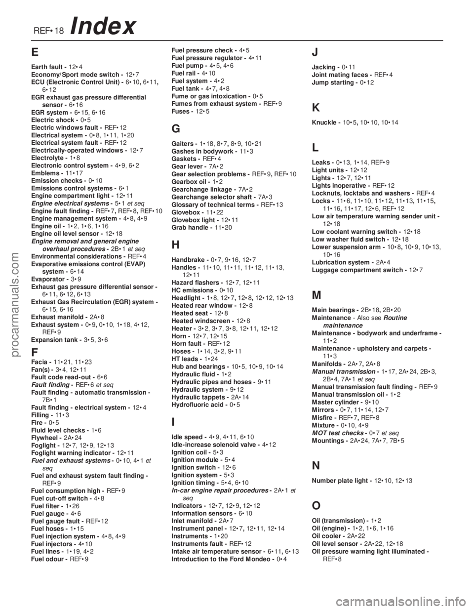
REF•18Index
E
Earth fault - 12•4
Economy/Sport mode switch - 12•7
ECU (Electronic Control Unit) - 6•10, 6•11,
6•12
EGR exhaust gas pressure differential
sensor - 6•16
EGR system - 6•15, 6•16
Electric shock - 0•5
Electric windows fault - REF•12
Electrical system - 0•8, 1•11, 1•20
Electrical system fault - REF•12
Electrically-operated windows - 12•7
Electrolyte - 1•8
Electronic control system - 4•9, 6•2
Emblems - 11•17
Emission checks - 0•10
Emissions control systems - 6•1
Engine compartment light - 12•11
Engine electrical systems- 5•1et seq
Engine fault finding - REF•7, REF•8, REF•10
Engine management system - 4•8, 4•9
Engine oil - 1•2, 1•6, 1•16
Engine oil level sensor - 12•18
Engine removal and general engine
overhaul procedures- 2B•1et seq
Environmental considerations - REF•4
Evaporative emissions control (EVAP)
system - 6•14
Evaporator - 3•9
Exhaust gas pressure differential sensor -
6•11, 6•12, 6•13
Exhaust Gas Recirculation (EGR) system -
6•15, 6•16
Exhaust manifold - 2A•8
Exhaust system - 0•9, 0•10, 1•18, 4•12,
REF•9
Expansion tank - 3•5, 3•6
FFacia - 11•21, 11•23
Fan(s) - 3•4, 12•11
Fault code read-out - 6•6
Fault finding- REF•6et seq
Fault finding - automatic transmission -
7B•1
Fault finding - electrical system - 12•4
Filling - 11•3
Fire - 0•5
Fluid level checks - 1•6
Flywheel - 2A•24
Foglight - 12•7, 12•9, 12•13
Foglight warning indicator - 12•11
Fuel and exhaust systems- 0•10, 4•1et
seq
Fuel and exhaust system fault finding -
REF•9
Fuel consumption high - REF•9
Fuel cut-off switch - 4•8
Fuel filter - 1•26
Fuel gauge - 4•6
Fuel gauge fault - REF•12
Fuel hoses - 1•15
Fuel injection system - 4•8, 4•9
Fuel injectors - 4•10
Fuel lines - 1•19, 4•2
Fuel odour - REF•9Fuel pressure check - 4•5
Fuel pressure regulator - 4•11
Fuel pump - 4•5, 4•6
Fuel rail - 4•10
Fuel system - 4•2
Fuel tank - 4•7, 4•8
Fume or gas intoxication - 0•5
Fumes from exhaust system - REF•9
Fuses - 12•5
G
Gaiters - 1•18, 8•7, 8•9, 10•21
Gashes in bodywork - 11•3
Gaskets - REF•4
Gear lever - 7A•2
Gear selection problems - REF•9, REF•10
Gearbox oil - 1•2
Gearchange linkage - 7A•2
Gearchange selector shaft - 7A•3
Glossary of technical terms - REF•13
Glovebox - 11•22
Glovebox light - 12•11
Grab handle - 11•20
H
Handbrake - 0•7, 9•16, 12•7
Handles - 11•10, 11•11, 11•12, 11•13,
12•11
Hazard flashers - 12•7, 12•11
HC emissions - 0•10
Headlight - 1•8, 12•7, 12•8, 12•12, 12•13
Heated rear window - 12•8
Heated seat - 12•8
Heated windscreen - 12•8
Heater - 3•2, 3•7, 3•8, 12•11, 12•12
Horn - 12•7, 12•15
Horn fault - REF•12
Hoses - 1•14, 3•2, 9•11
HT leads - 1•24
Hub and bearings - 10•5, 10•9, 10•14
Hydraulic fluid - 1•2
Hydraulic pipes and hoses - 9•11
Hydraulic system - 9•12
Hydraulic tappets - 2A•14
Hydrofluoric acid - 0•5
I
Idle speed - 4•9, 4•11, 6•10
Idle-increase solenoid valve - 4•12
Ignition coil - 5•3
Ignition module - 5•4
Ignition switch - 12•6
Ignition system - 5•3
Ignition timing - 5•4, 6•10
In-car engine repair procedures- 2A•1et
seq
Indicators - 12•7, 12•9, 12•12
Information sensors - 6•10
Inlet manifold - 2A•7
Instrument panel - 12•7, 12•11, 12•14
Instruments - 1•20
Instruments fault - REF•12
Intake air temperature sensor - 6•11, 6•13
Introduction to the Ford Mondeo - 0•4
J
Jacking - 0•11
Joint mating faces - REF•4
Jump starting - 0•12
K
Knuckle - 10•5, 10•10, 10•14
L
Leaks - 0•13, 1•14, REF•9
Light units - 12•12
Lights - 12•7, 12•11
Lights inoperative - REF•12
Locknuts, locktabs and washers - REF•4
Locks - 11•6, 11•10, 11•12, 11•13, 11•15,
11•16, 11•17, 12•6, REF•12
Low air temperature warning sender unit -
12•18
Low coolant warning switch - 12•18
Low washer fluid switch - 12•18
Lower suspension arm - 10•8, 10•9, 10•13,
10•16
Lubrication system - 2A•4
Luggage compartment switch - 12•7
M
Main bearings - 2B•18, 2B•20
Maintenance- Also see Routine
maintenance
Maintenance - bodywork and underframe -
11•2
Maintenance - upholstery and carpets -
11•3
Manifolds - 2A•7, 2A•8
Manual transmission- 1•17, 2A•24, 2B•3,
2B•4, 7A•1et seq
Manual transmission fault finding - REF•9
Manual transmission oil - 1•2
Master cylinder - 9•10
Mirrors - 0•7, 11•14, 12•7
Misfire - REF•7, REF•8
Mixture - 0•10, 4•9
MOT test checks- 0•7et seq
Mountings - 2A•24, 7A•7, 7B•5
N
Number plate light - 12•10, 12•13
O
Oil (transmission) - 1•2
Oil (engine) - 1•2, 1•6, 1•16
Oil cooler - 2A•22
Oil level sensor - 2A•22, 12•18
Oil pressure warning light illuminated -
REF•8
procarmanuals.com