torque FORD MONDEO 1993 Service Manual Online
[x] Cancel search | Manufacturer: FORD, Model Year: 1993, Model line: MONDEO, Model: FORD MONDEO 1993Pages: 279, PDF Size: 12.71 MB
Page 178 of 279
Chapter 11 Bodywork and fittings
Body side-trim mouldings and adhesive emblems - removal
and refitting . . . . . . . . . . . . . . . . . . . . . . . . . . . . . . . . . . . . . . . . . . 25
Bonnet - removal, refitting and adjustment . . . . . . . . . . . . . . . . . . . . 8
Bonnet lock - removal, refitting and adjustment . . . . . . . . . . . . . . . . 10
Bonnet release cable and lever - removal and refitting . . . . . . . . . . . 9
Boot lid - removal and refitting . . . . . . . . . . . . . . . . . . . . . . . . . . . . . 18
Boot lid lock components - removal and refitting . . . . . . . . . . . . . . . 19
Bumpers - removal and refitting . . . . . . . . . . . . . . . . . . . . . . . . . . . . 6
Central locking system components - testing, removal and refitting . 23
Centre console - removal and refitting . . . . . . . . . . . . . . . . . . . . . . . 30
Door - removal and refitting . . . . . . . . . . . . . . . . . . . . . . . . . . . . . . . 15
Door handle and lock components - removal and refitting . . . . . . . . 14
Door inner trim panel - removal and refitting . . . . . . . . . . . . . . . . . . 11
Door window glass - removal and refitting . . . . . . . . . . . . . . . . . . . . 12
Door window regulator - removal and refitting . . . . . . . . . . . . . . . . . 13
Exterior mirror and glass - removal and refitting . . . . . . . . . . . . . . . . 16
Facia - removal and refitting . . . . . . . . . . . . . . . . . . . . . . . . . . . . . . . 33
General information . . . . . . . . . . . . . . . . . . . . . . . . . . . . . . . . . . . . . . 1Glovebox - removal and refitting . . . . . . . . . . . . . . . . . . . . . . . . . . . . 32
Interior mirror - removal and refitting . . . . . . . . . . . . . . . . . . . . . . . . 17
Interior trim panels - removal and refitting . . . . . . . . . . . . . . . . . . . . 29
Maintenance - bodywork and underframe . . . . . . . . . . . . . . . . . . . . 2
Maintenance - upholstery and carpets . . . . . . . . . . . . . . . . . . . . . . . 3
Major body damage - repair . . . . . . . . . . . . . . . . . . . . . . . . . . . . . . . 5
Minor body damage - repair . . . . . . . . . . . . . . . . . . . . . . . . . . . . . . . 4
Overhead console - removal and refitting . . . . . . . . . . . . . . . . . . . . . 31
Radiator grille - removal and refitting . . . . . . . . . . . . . . . . . . . . . . . . 7
Seat belts - removal and refitting . . . . . . . . . . . . . . . . . . . . . . . . . . . 28
Seats - removal and refitting . . . . . . . . . . . . . . . . . . . . . . . . . . . . . . . 27
Sunroof - general information and adjustment . . . . . . . . . . . . . . . . . 26
Tailgate - removal and refitting . . . . . . . . . . . . . . . . . . . . . . . . . . . . . 20
Tailgate lock components - removal and refitting . . . . . . . . . . . . . . . 22
Tailgate support strut - removal and refitting . . . . . . . . . . . . . . . . . . 21
Wheel arch liner - removal and refitting . . . . . . . . . . . . . . . . . . . . . . 34
Windscreen and fixed windows - removal and refitting . . . . . . . . . . 24
Torque wrench settingsNm lbf ft
Bonnet and tailgate hinges . . . . . . . . . . . . . . . . . . . . . . . . . . . . . . . . . . . 24 18
Boot lid . . . . . . . . . . . . . . . . . . . . . . . . . . . . . . . . . . . . . . . . . . . . . . . . . . 10 7
Front seat mounting bolts . . . . . . . . . . . . . . . . . . . . . . . . . . . . . . . . . . . . 38 28
Seat belt mounting nuts and bolts . . . . . . . . . . . . . . . . . . . . . . . . . . . . . 38 28
Bumper mounting nuts . . . . . . . . . . . . . . . . . . . . . . . . . . . . . . . . . . . . . . 10 7
11•1
Easy,suitable for
novice with little
experienceFairly easy,suitable
for beginner with
some experienceFairly difficult,suitable
for competent DIY
mechanicDifficult,suitable for
experienced DIY
mechanicVery difficult,
suitable for expert DIY
or professional
Degrees of difficulty
Specifications Contents
11
The bodyshell and underframe on all
models is of all-steel welded construction,
incorporating progressive crumple zones at
the front and rear, and a rigid centre safety
cell. The bulkhead behind the engine
compartment incorporates crash grooves
which determine its energy-absorption
characteristics, and special beams to prevent
the intrusion of the front wheels into the
passenger compartment during a serious
accident. All passenger doors incorporate
side impact bars.
All sheet metal surfaces which are prone tocorrosion are galvanized. The painting
process includes a base colour which closely
matches the final topcoat, so that any stone
damage is not noticeable.
Hatchback, Saloon and Estate versions are
available. The front section of the vehicle up to
the “B” pillar is identical on all models.
Automatic seat belts are fitted to all models,
and the front seat belt stalks are mounted on
automatic tensioners (also known as
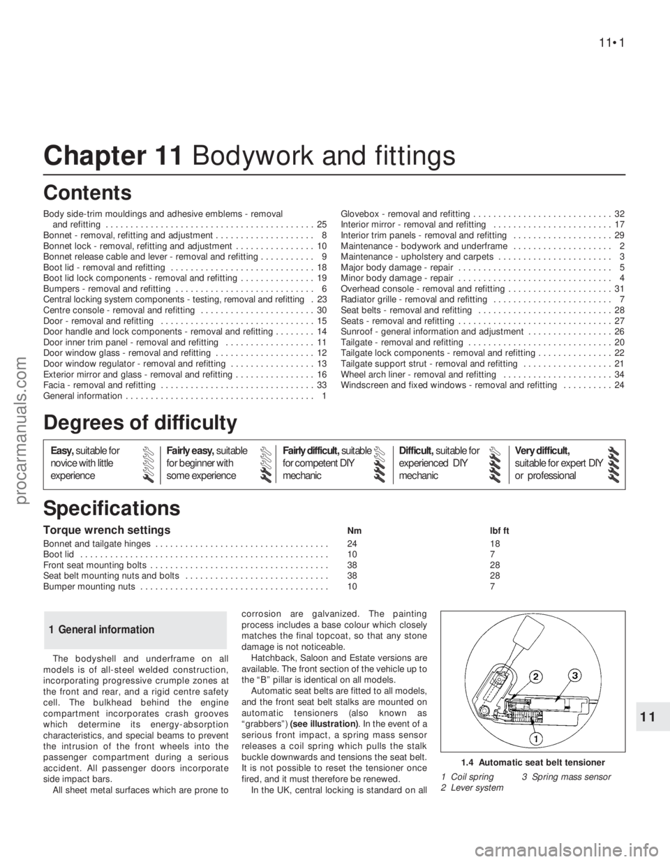
“grabbers”) (see illustration). In the event of a
serious front impact, a spring mass sensor
releases a coil spring which pulls the stalk
buckle downwards and tensions the seat belt.
It is not possible to reset the tensioner once
fired, and it must therefore be renewed.
In the UK, central locking is standard on all
1 General information
1.4 Automatic seat belt tensioner
1 Coil spring 3 Spring mass sensor
2 Lever system
procarmanuals.com
Page 195 of 279
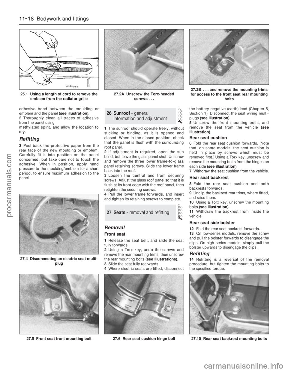
adhesive bond between the moulding or
emblem and the panel (see illustration).
2Thoroughly clean all traces of adhesive
from the panel using
methylated spirit, and allow the location to
dry.
Refitting
3Peel back the protective paper from the
rear face of the new moulding or emblem.
Carefully fit it into position on the panel
concerned, but take care not to touch the
adhesive. When in position, apply hand
pressure to the moulding/emblem for a short
period, to ensure maximum adhesion to the
panel.1The sunroof should operate freely, without
sticking or binding, as it is opened and
closed. When in the closed position, check
that the panel is flush with the surrounding
roof panel.
2If adjustment is required, open the sun
blind, but leave the glass panel shut. Unscrew
and remove the three lower frame-to-glass
panel retaining screws. Slide the lower frame
back into the roof.
3Loosen the central and front securing
screws. Adjust the glass roof panel so that it is
flush at its front edge with the roof panel, then
retighten the securing screws.
4Pull the lower frame forwards, and insert
and tighten its retaining screws to complete.
Removal
Front seat
1Release the seat belt, and slide the seat
fully forwards.
2Using a Torx key, undo the screws and
remove the rear mounting trims, then unscrew
the rear mounting bolts (see illustrations).
3Slide the seat fully rearwards.
4Where electric seats are fitted, disconnectthe battery negative (earth) lead (Chapter 5,
Section 1). Disconnect the seat wiring multi-
plugs (see illustration).
5Unscrew the front mounting bolts, and
remove the seat from the vehicle (see
illustration).
Rear seat cushion
6Fold the rear seat cushion forwards. (Note
that, on some models, the seat cushion is
held in place by screws which must be
removed first.) Using a Torx key, unscrew and
remove the mounting bolts from the hinges on
each side (see illustration).
7Withdraw the seat cushion from the vehicle.
Rear seat backrest
8Fold the rear seat cushion and both
backrests forwards.
9Unclip the backrest rear trims, where fitted,
and raise them.
10Using a Torx key, unscrew the mounting
bolts (see illustration).
11Withdraw the backrest from inside the
vehicle.
Rear seat side bolster
12Fold the rear seat backrest forwards.
13On low-series models, remove the screw
and pull the bolster forwards to disengage the
clips. On high-series models, simply pull the
bolster upwards to disengage the clips.
Refitting
14Refitting is a reversal of the removal
procedure, but tighten the mounting bolts to
the specified torque.
27 Seats - removal and refitting
26 Sunroof - general
information and adjustment
11•18 Bodywork and fittings
25.1 Using a length of cord to remove the
emblem from the radiator grille27.2A Unscrew the Torx-headed
screws . . .27.2B . . . and remove the mounting trims
for access to the front seat rear mounting
bolts
27.5 Front seat front mounting bolt
27.4 Disconnecting an electric seat multi-
plug
27.6 Rear seat cushion hinge bolt27.10 Rear seat backrest mounting bolts
procarmanuals.com
Page 197 of 279
8Unscrew the mounting bolt securing the
seat belt stalk, and withdraw the stalk. Also
unscrew the mounting bolt from the lower
anchorage, where applicable (see
illustration).
Rear centre seat belt
9Unscrew the mounting bolts securing the
seat belt and stalks to the floor. Note that the
stalks are handed, and are marked Left or
Right.
Refitting
10Refitting is a reversal of the removal
procedure. Tighten the mounting nuts and
bolts to the specified torque.
Removal
Sun visor
1Disconnect the wiring for the vanity mirror
light, where fitted.
2Unscrew the mounting screws and remove
the visor.
3Prise up the cover, unscrew the inner
bracket mounting screws, and remove the
bracket.
Passenger grab handle
4Prise up the covers, then unscrew the
mounting screws and remove the grab
handle.
“A” pillar trim
5Pull away the door weatherstrip in the area
of the trim.
6Release the alarm and aerial wiring from the
upper and middle clips.
7Carefully press the trim away from the
upper and middle clips, and pull the trim
upwards. Recover the lower sealing strip.
8Remove the upper and middle clips from
the pillar.
“B” pillar and cowl side trim
9Pull away the door weatherstrip in the area
of the trim.
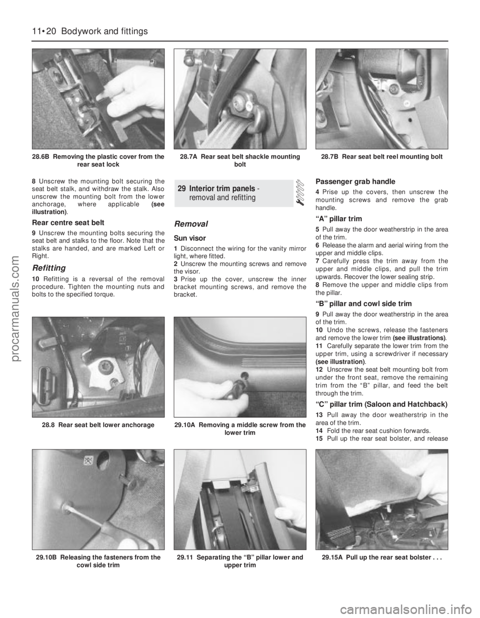
10Undo the screws, release the fasteners
and remove the lower trim (see illustrations).
11Carefully separate the lower trim from the
upper trim, using a screwdriver if necessary
(see illustration).
12Unscrew the seat belt mounting bolt from
under the front seat, remove the remaining
trim from the “B” pillar, and feed the belt
through the trim.
“C” pillar trim (Saloon and Hatchback)
13Pull away the door weatherstrip in the
area of the trim.
14Fold the rear seat cushion forwards.
15Pull up the rear seat bolster, and release
29 Interior trim panels-
removal and refitting
11•20 Bodywork and fittings
28.6B Removing the plastic cover from the
rear seat lock28.7A Rear seat belt shackle mounting
bolt28.7B Rear seat belt reel mounting bolt
29.10B Releasing the fasteners from the
cowl side trim29.11 Separating the “B” pillar lower and
upper trim
28.8 Rear seat belt lower anchorage29.10A Removing a middle screw from the
lower trim
29.15A Pull up the rear seat bolster . . .
procarmanuals.com
Page 198 of 279

the upper hook. Note that, on low-series
models, the bolster is retained with a screw
(see illustrations).
16Undo the screw, release the clips, and
detach the upper trim.
17Remove the rear seat belt lower mounting
bolt, then remove the trim, and pass the seat
belt through it.
“C” pillar trim (Estate)
18Prise off the caps, unscrew the screws,
and remove the upper trim from the “C” pillar
(see illustration).
19Unscrew the mounting bolt securing the
rear seat belt upper shackle to the “C” pillar.
20Unclip and remove the trim.
“D” pillar trim (Estate)
21Remove the three mounting screws, then
unclip the trim from the “D” pillar.
Lower facia panel
22Remove the steering column top and
bottom shrouds.
23Unscrew the mounting screws from the
upper corners and above the coin tray
position, and withdraw the lower facia panel
from the facia (see illustrations).
Refitting
24Refitting is a reversal of the removal
procedure. Where seat belt fastenings have
been disturbed, make sure that they are
tightened to the specified torque.
Removal
1Disconnect the battery negative (earth) lead
(Chapter 5, Section 1).
2Pull the ashtray from the facia.
3Pull off the gear lever (or selector lever)
knob (see illustration).
4Using a screwdriver, carefully prise out the
gear lever gaiter/switch panel or selector lever
panel, as applicable. When necessary,
disconnect the wiring multi-plugs (see
illustration).
5Remove the adaptive damping switch,
when fitted (Chapter 12).
30 Centre console-
removal and refitting
Bodywork and fittings 11•21
11
30.4 Prising out the gear lever gaiter30.6A Prise off the plastic caps . . .30.6B . . . and unscrew the mounting
screws at the front top . . .
29.23B . . . and above the coin tray
position . . .
29.23C . . . and withdraw the lower facia
panel30.3 Gear lever knob removal
29.15B . . . and release the upper hook29.18 Screw locations (arrowed) for the
“C” pillar upper trim - Estate models29.23A Unscrew the mounting screws
from the upper corners . . .
procarmanuals.com
Page 201 of 279

Refitting
24Refitting is a reversal of the removal
procedure. On completion, check the
operation of all electrical components.
Removal
Front
1Apply the handbrake, jack up the front of
the vehicle and support it on axle stands. Ifwished, remove the wheel to improve access.
2Prise out the stud clip on the front lower
edge of the liner.
3Using a Torx key, unscrew the screws
securing the liner to the inner wheel arch
panel (see illustration).
4Remove the screws and clips securing the
liner to the outer edge of the wheel arch and
bumper. Withdraw the liner from under the
vehicle (see illustration).
Rear
5Chock the front wheels, jack up the rear of
the vehicle and support it on axle stands. If
wished, remove the wheel to improve access.6Unscrew and remove the nuts, located on
either side of the coil spring, securing the
central section of the liner.
7Using a Torx key, unscrew the screws
securing the liner to the centre of the inner
wheel arch panel.
8Remove the clips securing the liner to the
outer edge of the wheel arch, and withdraw
the liner from under the vehicle.
Refitting
9Refitting is a reversal of the removal
procedure. If the wheels were removed,
tighten the wheel nuts to the specified torque.
34 Wheel arch liner-
removal and refitting
11•24 Bodywork and fittings
33.22 Disconnecting the fresh air hoses34.3 Removing a wheel arch liner retaining
screw34.4 Removing a front wheel arch liner
procarmanuals.com
Page 204 of 279
BulbsWattage Type
Headlight main beam . . . . . . . . . . . . . . . . . . . . . . . . . . . . . . . . . . . . . . . 55 Halogen
Headlight dipped beam . . . . . . . . . . . . . . . . . . . . . . . . . . . . . . . . . . . . . . 55 Halogen
Foglights . . . . . . . . . . . . . . . . . . . . . . . . . . . . . . . . . . . . . . . . . . . . . . . . . 55 Halogen
Sidelights . . . . . . . . . . . . . . . . . . . . . . . . . . . . . . . . . . . . . . . . . . . . . . . . . 5 Wedge
Direction indicator lights . . . . . . . . . . . . . . . . . . . . . . . . . . . . . . . . . . . . . 21 Bayonet
Side repeater lights . . . . . . . . . . . . . . . . . . . . . . . . . . . . . . . . . . . . . . . . . 5 Wedge
Stop-lights . . . . . . . . . . . . . . . . . . . . . . . . . . . . . . . . . . . . . . . . . . . . . . . . 21 Bayonet
Reversing lights . . . . . . . . . . . . . . . . . . . . . . . . . . . . . . . . . . . . . . . . . . . . 21 Bayonet
Rear fog/tail lights (Saloon and Estate) . . . . . . . . . . . . . . . . . . . . . . . . . . 21/4 Bayonet
Rear tail light (Saloon and Hatchback) . . . . . . . . . . . . . . . . . . . . . . . . . . 5 Bayonet
Number plate lights . . . . . . . . . . . . . . . . . . . . . . . . . . . . . . . . . . . . . . . . . 5 Festoon
Engine compartment . . . . . . . . . . . . . . . . . . . . . . . . . . . . . . . . . . . . . . . . 10 Wedge
Interior lights . . . . . . . . . . . . . . . . . . . . . . . . . . . . . . . . . . . . . . . . . . . . . . 10 Festoon
Reading light . . . . . . . . . . . . . . . . . . . . . . . . . . . . . . . . . . . . . . . . . . . . . . 5 Wedge
Torque wrench settingsNm lbf ft
Windscreen wiper motor bolts:
Into old motor (see text) . . . . . . . . . . . . . . . . . . . . . . . . . . . . . . . . . . . 8 6
Into new motor (see text) . . . . . . . . . . . . . . . . . . . . . . . . . . . . . . . . . . . 12 9
Body electrical system 12•3
12
Warning: Before carrying out any
work on the electrical system,
read through the precautions
given in “Safety first!” at the beginning of
this manual.The electrical system is of 12-volt negative
earth type. Power for the lights and all
electrical accessories is supplied by a
lead/acid battery which is charged by the
alternator.
This Chapter covers repair and service
procedures for the various electrical
components not associated with the engine.
Information on the battery, ignition system,alternator, and starter motor can be found in
Chapter 5.
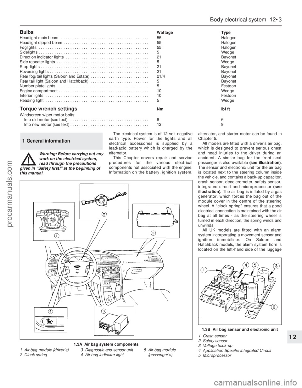
All models are fitted with a driver’s air bag,
which is designed to prevent serious chest
and head injuries to the driver during an
accident. A similar bag for the front seat
passenger is also available (see illustration).
The sensor and electronic unit for the air bag
is located next to the steering column inside
the vehicle, and contains a back-up capacitor,
crash sensor, decelerometer, safety sensor,
integrated circuit and microprocessor (see
illustration). The air bag is inflated by a gas
generator, which forces the bag out of the
module cover in the centre of the steering
wheel. A “clock spring” ensures that a good
electrical connection is maintained with the air
bag at all times - as the steering wheel is
turned in each direction, the spring winds and
unwinds.
All UK models are fitted with an alarm
system incorporating a movement sensor and
ignition immobiliser. On Saloon and
Hatchback models, the alarm system horn is
located on the left-hand side of the luggage
1 General information
1.3A Air bag system components
1 Air bag module (driver’s)
2 Clock spring3 Diagnostic and sensor unit
4 Air bag indicator light5 Air bag module
(passenger’s)
1.3B Air bag sensor and electronic unit
1 Crash sensor
2 Safety sensor
3 Voltage back-up
4 Application Specific Integrated Circuit
5 Microprocessor
procarmanuals.com
Page 218 of 279
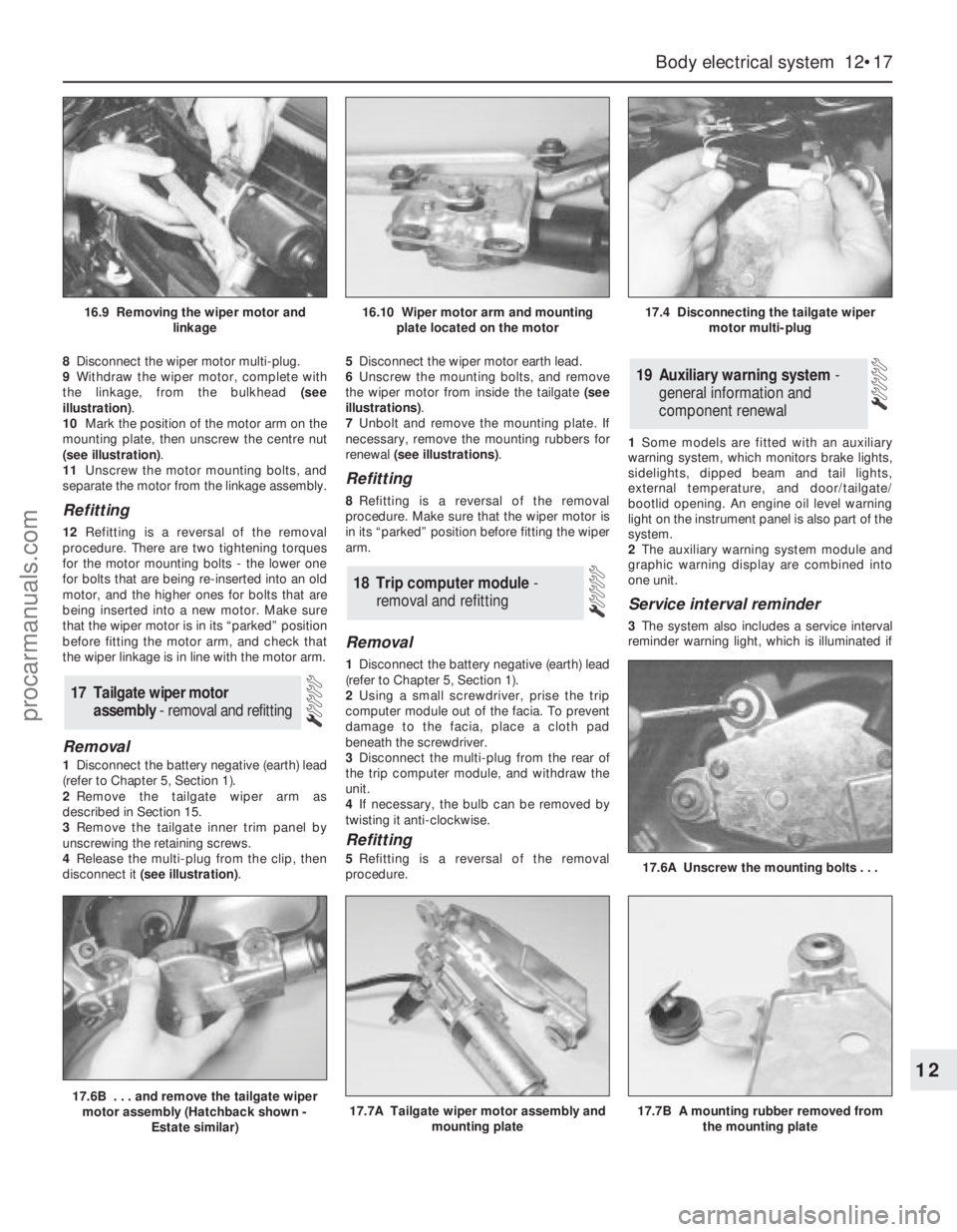
8Disconnect the wiper motor multi-plug.
9Withdraw the wiper motor, complete with
the linkage, from the bulkhead (see
illustration).
10Mark the position of the motor arm on the
mounting plate, then unscrew the centre nut
(see illustration).
11Unscrew the motor mounting bolts, and
separate the motor from the linkage assembly.
Refitting
12Refitting is a reversal of the removal
procedure. There are two tightening torques
for the motor mounting bolts - the lower one
for bolts that are being re-inserted into an old
motor, and the higher ones for bolts that are
being inserted into a new motor. Make sure
that the wiper motor is in its “parked” position
before fitting the motor arm, and check that
the wiper linkage is in line with the motor arm.
Removal
1Disconnect the battery negative (earth) lead
(refer to Chapter 5, Section 1).
2Remove the tailgate wiper arm as
described in Section 15.
3Remove the tailgate inner trim panel by
unscrewing the retaining screws.
4Release the multi-plug from the clip, then
disconnect it (see illustration).5Disconnect the wiper motor earth lead.
6Unscrew the mounting bolts, and remove
the wiper motor from inside the tailgate (see
illustrations).
7Unbolt and remove the mounting plate. If
necessary, remove the mounting rubbers for
renewal (see illustrations).
Refitting
8Refitting is a reversal of the removal
procedure. Make sure that the wiper motor is
in its “parked” position before fitting the wiper
arm.
Removal
1Disconnect the battery negative (earth) lead
(refer to Chapter 5, Section 1).
2Using a small screwdriver, prise the trip
computer module out of the facia. To prevent
damage to the facia, place a cloth pad
beneath the screwdriver.
3Disconnect the multi-plug from the rear of
the trip computer module, and withdraw the
unit.
4If necessary, the bulb can be removed by
twisting it anti-clockwise.
Refitting
5Refitting is a reversal of the removal
procedure.1Some models are fitted with an auxiliary
warning system, which monitors brake lights,
sidelights, dipped beam and tail lights,
external temperature, and door/tailgate/
bootlid opening. An engine oil level warning
light on the instrument panel is also part of the
system.
2The auxiliary warning system module and
graphic warning display are combined into
one unit.
Service interval reminder
3The system also includes a service interval
reminder warning light, which is illuminated if
19 Auxiliary warning system -
general information and
component renewal
18 Trip computer module-
removal and refitting
17 Tailgate wiper motor
assembly - removal and refitting
Body electrical system 12•17
12
17.6B . . . and remove the tailgate wiper
motor assembly (Hatchback shown -
Estate similar)17.7A Tailgate wiper motor assembly and
mounting plate17.7B A mounting rubber removed from
the mounting plate
17.6A Unscrew the mounting bolts . . .
16.9 Removing the wiper motor and
linkage16.10 Wiper motor arm and mounting
plate located on the motor17.4 Disconnecting the tailgate wiper
motor multi-plug
procarmanuals.com
Page 260 of 279
Introduction
A selection of good tools is a fundamental
requirement for anyone contemplating the
maintenance and repair of a motor vehicle.
For the owner who does not possess any,
their purchase will prove a considerable
expense, offsetting some of the savings made
by doing-it-yourself. However, provided that
the tools purchased meet the relevant national
safety standards and are of good quality, they
will last for many years and prove an
extremely worthwhile investment.
To help the average owner to decide which
tools are needed to carry out the various tasks
detailed in this manual, we have compiled
three lists of tools under the following
headings: Maintenance and minor repair,
Repair and overhaul, and Special. Newcomers
to practical mechanics should start off with
the Maintenance and minor repairtool kit, and
confine themselves to the simpler jobs around
the vehicle. Then, as confidence and
experience grow, more difficult tasks can be
undertaken, with extra tools being purchased
as, and when, they are needed. In this way, a
Maintenance and minor repairtool kit can be
built up into a Repair and overhaultool kit over
a considerable period of time, without any
major cash outlays. The experienced do-it-
yourselfer will have a tool kit good enough for
most repair and overhaul procedures, and will
add tools from the Specialcategory when it is
felt that the expense is justified by the amount
of use to which these tools will be put.
Maintenance and minor repair
tool kit
The tools given in this list should be
considered as a minimum requirement if
routine maintenance, servicing and minor
repair operations are to be undertaken. We
recommend the purchase of combination
spanners (ring one end, open-ended the
other); although more expensive than open-
ended ones, they do give the advantages of
both types of spanner.
MCombination spanners:
Metric - 8, 9, 10, 11, 12, 13, 14, 15, 16, 17,
19, 21, 22, 24 & 26 mm
MAdjustable spanner - 35 mm jaw (approx)
MTransmission drain plug key (Allen type)
MSet of feeler gauges
MSpark plug spanner (with rubber insert)
MSpark plug gap adjustment tool
MBrake adjuster spanner (where applicable)
MBrake bleed nipple spanner
MScrewdrivers:
Flat blade - approx 100 mm long x 6 mm dia
Cross blade - approx 100 mm long x
6 mm dia
MCombination pliers
MHacksaw (junior)
MTyre pump
MTyre pressure gauge
MOil can
MOil filter removal tool
MFine emery cloth
MWire brush (small)
MFunnel (medium size)
Repair and overhaul tool kit
These tools are virtually essential for
anyone undertaking any major repairs to a
motor vehicle, and are additional to those
given in the Maintenance and minor repairlist.
Included in this list is a comprehensive set of
sockets. Although these are expensive, they
will be found invaluable as they are so
versatile - particularly if various drives are
included in the set. We recommend the half-
inch square-drive type, as this can be used
with most proprietary torque wrenches. If you
cannot afford a socket set, even bought
piecemeal, then inexpensive tubular box
spanners are a useful alternative.
The tools in this list will occasionally need to
be supplemented by tools from the Special
list:
MSockets (or box spanners) to cover range in
previous list
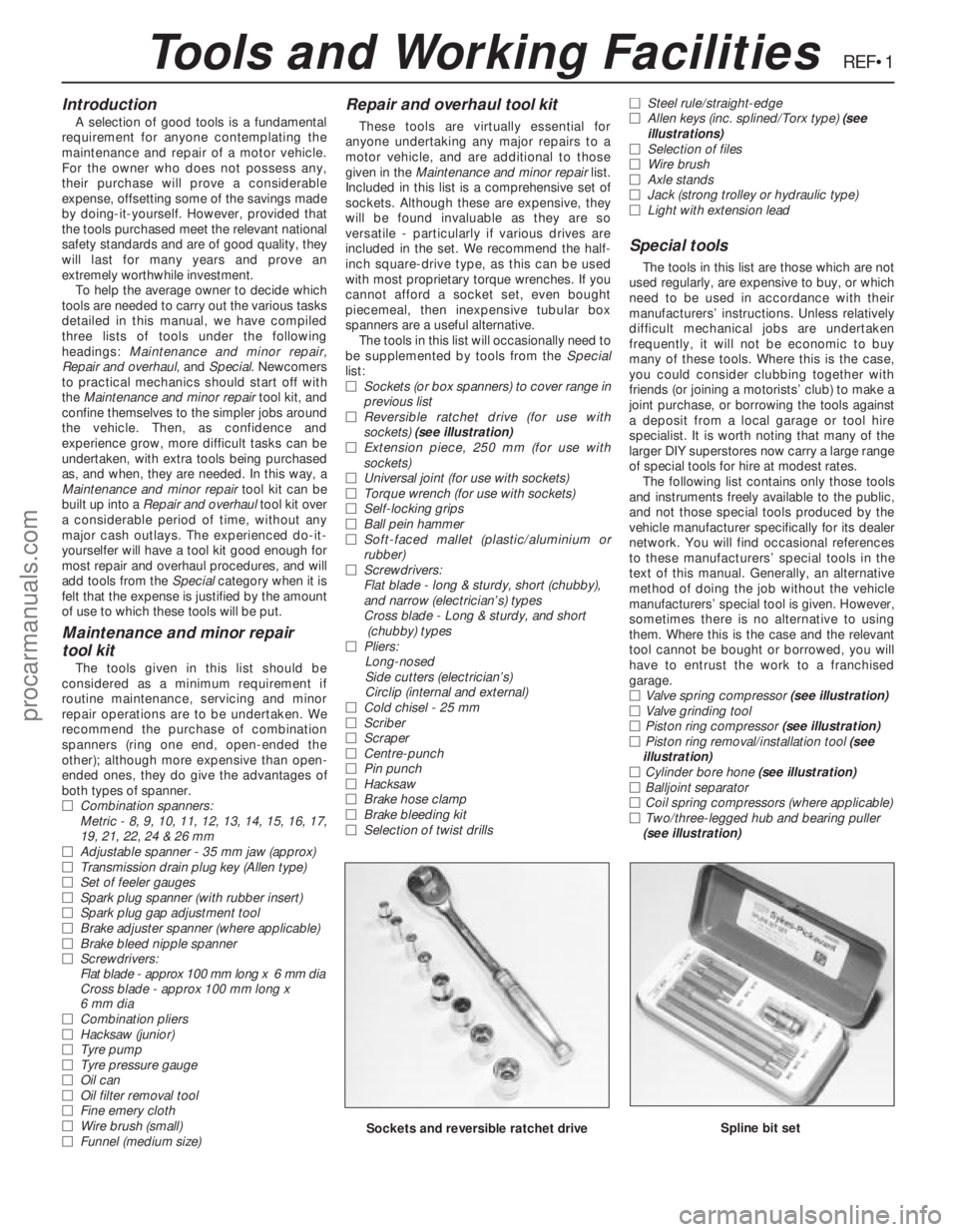
MReversible ratchet drive (for use with
sockets) (see illustration)
MExtension piece, 250 mm (for use with
sockets)
MUniversal joint (for use with sockets)
MTorque wrench (for use with sockets)
MSelf-locking grips
MBall pein hammer
MSoft-faced mallet (plastic/aluminium or
rubber)
MScrewdrivers:
Flat blade - long & sturdy, short (chubby),
and narrow (electrician’s) types
Cross blade - Long & sturdy, and short
(chubby) types
MPliers:
Long-nosed
Side cutters (electrician’s)
Circlip (internal and external)
MCold chisel - 25 mm
MScriber
MScraper
MCentre-punch
MPin punch
MHacksaw
MBrake hose clamp
MBrake bleeding kit
MSelection of twist drillsMSteel rule/straight-edge
MAllen keys (inc. splined/Torx type) (see
illustrations)
MSelection of files
MWire brush
MAxle stands
MJack (strong trolley or hydraulic type)
MLight with extension lead
Special tools
The tools in this list are those which are not
used regularly, are expensive to buy, or which
need to be used in accordance with their
manufacturers’ instructions. Unless relatively
difficult mechanical jobs are undertaken
frequently, it will not be economic to buy
many of these tools. Where this is the case,
you could consider clubbing together with
friends (or joining a motorists’ club) to make a
joint purchase, or borrowing the tools against
a deposit from a local garage or tool hire
specialist. It is worth noting that many of the
larger DIY superstores now carry a large range
of special tools for hire at modest rates.
The following list contains only those tools
and instruments freely available to the public,
and not those special tools produced by the
vehicle manufacturer specifically for its dealer
network. You will find occasional references
to these manufacturers’ special tools in the
text of this manual. Generally, an alternative
method of doing the job without the vehicle
manufacturers’ special tool is given. However,
sometimes there is no alternative to using
them. Where this is the case and the relevant
tool cannot be bought or borrowed, you will
have to entrust the work to a franchised
garage.
MValve spring compressor (see illustration)
MValve grinding tool
MPiston ring compressor (see illustration)
MPiston ring removal/installation tool (see
illustration)
MCylinder bore hone (see illustration)
MBalljoint separator
MCoil spring compressors (where applicable)
MTwo/three-legged hub and bearing puller
(see illustration)
REF•1
Sockets and reversible ratchet driveSpline bit set
Tools and Working Facilities
procarmanuals.com
Page 263 of 279
REF•4
Whenever servicing, repair or overhaul work
is carried out on the car or its components, it
is necessary to observe the following
procedures and instructions. This will assist in
carrying out the operation efficiently and to a
professional standard of workmanship.
Joint mating faces and gaskets
When separating components at their
mating faces, never insert screwdrivers or
similar implements into the joint between the
faces in order to prise them apart. This can
cause severe damage which results in oil
leaks, coolant leaks, etc upon reassembly.
Separation is usually achieved by tapping
along the joint with a soft-faced hammer in
order to break the seal. However, note that
this method may not be suitable where
dowels are used for component location.
Where a gasket is used between the mating
faces of two components, ensure that it is
renewed on reassembly, and fit it dry unless
otherwise stated in the repair procedure.
Make sure that the mating faces are clean and
dry, with all traces of old gasket removed.
When cleaning a joint face, use a tool which is
not likely to score or damage the face, and
remove any burrs or nicks with an oilstone or
fine file.
Make sure that tapped holes are cleaned
with a pipe cleaner, and keep them free of
jointing compound, if this is being used,
unless specifically instructed otherwise.
Ensure that all orifices, channels or pipes
are clear, and blow through them, preferably
using compressed air.
Oil seals
Oil seals can be removed by levering them
out with a wide flat-bladed screwdriver or
similar implement. Alternatively, a number of
self-tapping screws may be screwed into the
seal, and these used as a purchase for pliers
or some similar device in order to pull the seal
free.
Whenever an oil seal is removed from its
working location, either individually or as part
of an assembly, it should be renewed.
The very fine sealing lip of the seal is easily
damaged, and will not seal if the surface it
contacts is not completely clean and free from
scratches, nicks or grooves.
Protect the lips of the seal from any surface
which may damage them in the course of
fitting. Use tape or a conical sleeve where
possible. Lubricate the seal lips with oil before
fitting and, on dual-lipped seals, fill the space
between the lips with grease.
Unless otherwise stated, oil seals must be
fitted with their sealing lips toward the
lubricant to be sealed.
Use a tubular drift or block of wood of the
appropriate size to install the seal and, if the
seal housing is shouldered, drive the seal
down to the shoulder. If the seal housing is
unshouldered, the seal should be fitted with
its face flush with the housing top face (unless
otherwise instructed).
Screw threads and fastenings
Seized nuts, bolts and screws are quite a
common occurrence where corrosion has set
in, and the use of penetrating oil or releasing
fluid will often overcome this problem if the
offending item is soaked for a while before
attempting to release it. The use of an impact
driver may also provide a means of releasing
such stubborn fastening devices, when used
in conjunction with the appropriate
screwdriver bit or socket. If none of these
methods works, it may be necessary to resort
to the careful application of heat, or the use of
a hacksaw or nut splitter device.
Studs are usually removed by locking two
nuts together on the threaded part, and then
using a spanner on the lower nut to unscrew
the stud. Studs or bolts which have broken off
below the surface of the component in which
they are mounted can sometimes be removed
using a proprietary stud extractor. Always
ensure that a blind tapped hole is completely
free from oil, grease, water or other fluid
before installing the bolt or stud. Failure to do
this could cause the housing to crack due to
the hydraulic action of the bolt or stud as it is
screwed in.
When tightening a castellated nut to accept
a split pin, tighten the nut to the specified
torque, where applicable, and then tighten
further to the next split pin hole. Never slacken
the nut to align the split pin hole, unless stated
in the repair procedure.
When checking or retightening a nut or bolt
to a specified torque setting, slacken the nut
or bolt by a quarter of a turn, and then
retighten to the specified setting. However,
this should not be attempted where angular
tightening has been used.
For some screw fastenings, notably cylinder
head bolts or nuts, torque wrench settings are
no longer specified for the latter stages of
tightening, “angle-tightening” being called up
instead. Typically, a fairly low torque wrench
setting will be applied to the bolts/nuts in
the correct sequence, followed by one or
more stages of tightening through specified
angles.
Locknuts, locktabs and washers
Any fastening which will rotate against a
component or housing in the course of
tightening should always have a washer
between it and the relevant component or
housing.
Spring or split washers should always be
renewed when they are used to lock a critical
component such as a big-end bearing
retaining bolt or nut. Locktabs which are
folded over to retain a nut or bolt should
always be renewed.
Self-locking nuts can be re-used in non-
critical areas, providing resistance can be felt
when the locking portion passes over the bolt
or stud thread. However, it should be noted
that self-locking stiffnuts tend to lose theireffectiveness after long periods of use, and in
such cases should be renewed as a matter of
course.
Split pins must always be replaced with
new ones of the correct size for the hole.
When thread-locking compound is found
on the threads of a fastener which is to be re-
used, it should be cleaned off with a wire
brush and solvent, and fresh compound
applied on reassembly.
Special tools
Some repair procedures in this manual
entail the use of special tools such as a press,
two or three-legged pullers, spring
compressors, etc. Wherever possible, suitable
readily-available alternatives to the
manufacturer’s special tools are described,
and are shown in use. Unless you are highly-
skilled and have a thorough understanding of
the procedures described, never attempt to
bypass the use of any special tool when the
procedure described specifies its use. Not
only is there a very great risk of personal
injury, but expensive damage could be
caused to the components involved.
Environmental considerations
When disposing of used engine oil, brake
fluid, antifreeze, etc, give due consideration to
any detrimental environmental effects. Do not,
for instance, pour any of the above liquids
down drains into the general sewage system,
or onto the ground to soak away. Many local
council refuse tips provide a facility for waste
oil disposal, as do some garages. If none of
these facilities are available, consult your local
Environmental Health Department for further
advice.
With the universal tightening-up of
legislation regarding the emission of
environmentally-harmful substances from
motor vehicles, most current vehicles have
tamperproof devices fitted to the main
adjustment points of the fuel system. These
devices are primarily designed to prevent
unqualified persons from adjusting the fuel/air
mixture, with the chance of a consequent
increase in toxic emissions. If such devices
are encountered during servicing or overhaul,
they should, wherever possible, be renewed
or refitted in accordance with the vehicle
manufacturer’s requirements or current
legislation.
Note: It is
antisocial and
illegal to dump
oil down the
drain. To find
the location of
your local oil
recycling
bank, call this
number free.
General Repair Procedures
procarmanuals.com