clock FORD RANGER 2003 2.G User Guide
[x] Cancel search | Manufacturer: FORD, Model Year: 2003, Model line: RANGER, Model: FORD RANGER 2003 2.GPages: 248, PDF Size: 2.53 MB
Page 57 of 248
CARGO AREA FEATURES
Cargo area shade (if equipped)
Your vehicle may be equipped with notches in the side trim panels that
are used for a cargo area shade. See your dealer for more information.
BEDRAILS (IF EQUIPPED)
•This bedrail is for appearance use only.
•To help prevent injury, do not use bedrail to retain cargo.
•Retain cargo with the pickup tie down hooks.
BED EXTENDER (IF EQUIPPED)
Your vehicle may be equipped with a bed extender designed to extend
the pickup box for longer loads.
To extend the bed extender:
1. Lower tailgate.
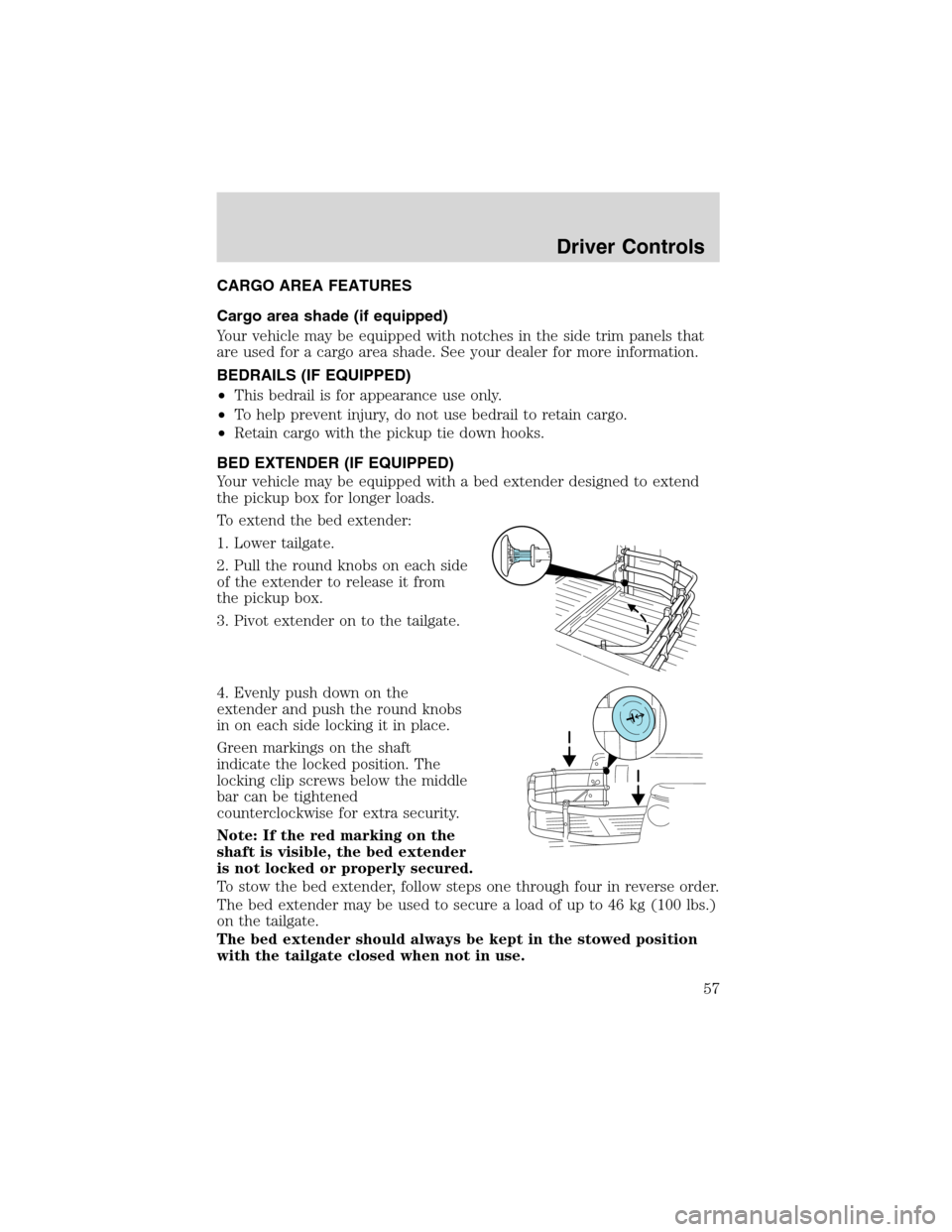
2. Pull the round knobs on each side
of the extender to release it from
the pickup box.
3. Pivot extender on to the tailgate.
4. Evenly push down on the
extender and push the round knobs
in on each side locking it in place.
Green markings on the shaft
indicate the locked position. The
locking clip screws below the middle
bar can be tightened
counterclockwise for extra security.
Note: If the red marking on the
shaft is visible, the bed extender
is not locked or properly secured.
To stow the bed extender, follow steps one through four in reverse order.
The bed extender may be used to secure a load of up to 46 kg (100 lbs.)
on the tailgate.
The bed extender should always be kept in the stowed position
with the tailgate closed when not in use.
Driver Controls
57
Page 72 of 248
Using the manual lumbar support (if equipped)
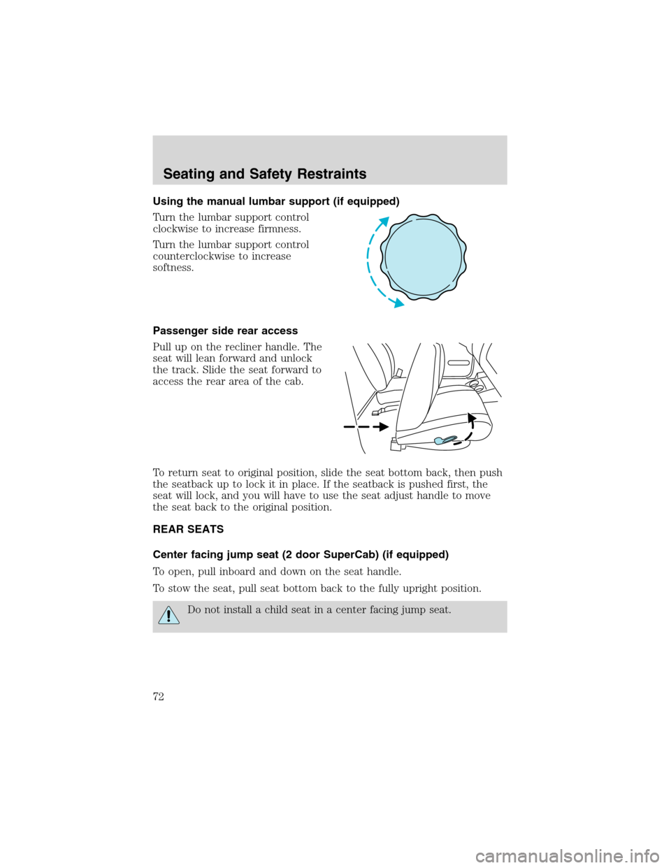
Turn the lumbar support control
clockwise to increase firmness.
Turn the lumbar support control
counterclockwise to increase
softness.
Passenger side rear access
Pull up on the recliner handle. The
seat will lean forward and unlock
the track. Slide the seat forward to
access the rear area of the cab.
To return seat to original position, slide the seat bottom back, then push
the seatback up to lock it in place. If the seatback is pushed first, the
seat will lock, and you will have to use the seat adjust handle to move
the seat back to the original position.
REAR SEATS
Center facing jump seat (2 door SuperCab) (if equipped)
To open, pull inboard and down on the seat handle.
To stow the seat, pull seat bottom back to the fully upright position.
Do not install a child seat in a center facing jump seat.
Seating and Safety Restraints
72
Page 161 of 248
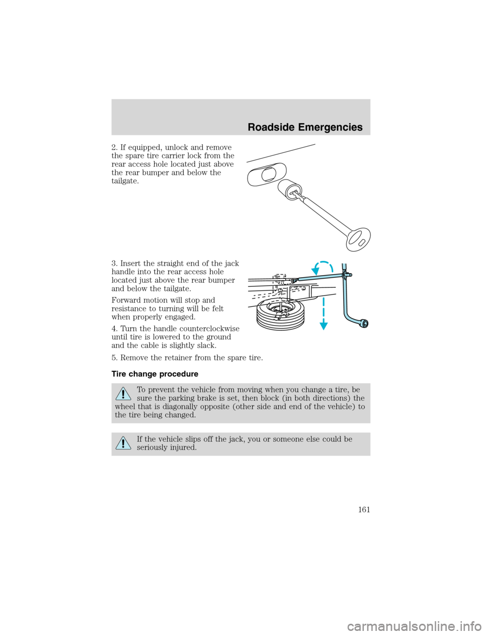
2. If equipped, unlock and remove
the spare tire carrier lock from the
rear access hole located just above
the rear bumper and below the
tailgate.
3. Insert the straight end of the jack
handle into the rear access hole
located just above the rear bumper
and below the tailgate.
Forward motion will stop and
resistance to turning will be felt
when properly engaged.
4. Turn the handle counterclockwise
until tire is lowered to the ground
and the cable is slightly slack.
5. Remove the retainer from the spare tire.
Tire change procedure
To prevent the vehicle from moving when you change a tire, be
sure the parking brake is set, then block (in both directions) the
wheel that is diagonally opposite (other side and end of the vehicle) to
the tire being changed.
If the vehicle slips off the jack, you or someone else could be
seriously injured.
Roadside Emergencies
161
Page 162 of 248
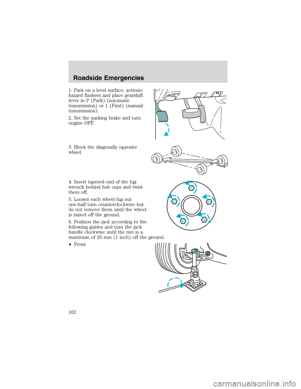
1. Park on a level surface, activate
hazard flashers and place gearshift
lever in P (Park) (automatic
transmission) or 1 (First) (manual
transmission).
2. Set the parking brake and turn
engine OFF.
3. Block the diagonally opposite
wheel.
4. Insert tapered end of the lug
wrench behind hub caps and twist
them off.
5. Loosen each wheel lug nut
one-half turn counterclockwise but
do not remove them until the wheel
is raised off the ground.
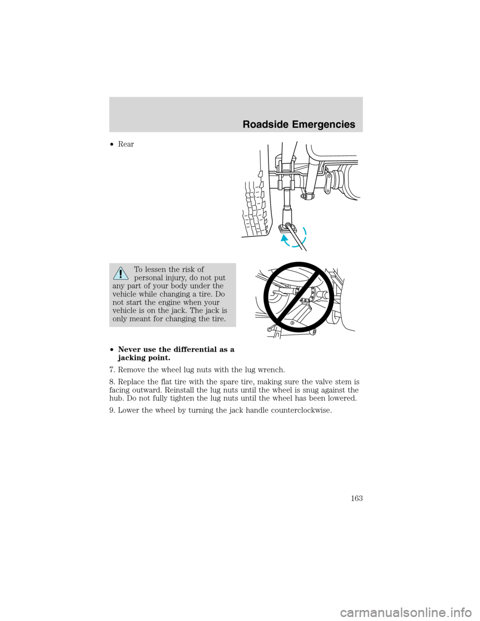
6. Position the jack according to the
following guides and turn the jack
handle clockwise until the tire is a
maximum of 25 mm (1 inch) off the ground.
•Front
Roadside Emergencies
162
Page 163 of 248
•Rear
To lessen the risk of
personal injury, do not put
any part of your body under the
vehicle while changing a tire. Do
not start the engine when your
vehicle is on the jack. The jack is
only meant for changing the tire.
•Never use the differential as a
jacking point.
7. Remove the wheel lug nuts with the lug wrench.
8. Replace the flat tire with the spare tire, making sure the valve stem is
facing outward. Reinstall the lug nuts until the wheel is snug against the
hub. Do not fully tighten the lug nuts until the wheel has been lowered.
9. Lower the wheel by turning the jack handle counterclockwise.
Roadside Emergencies
163
Page 164 of 248
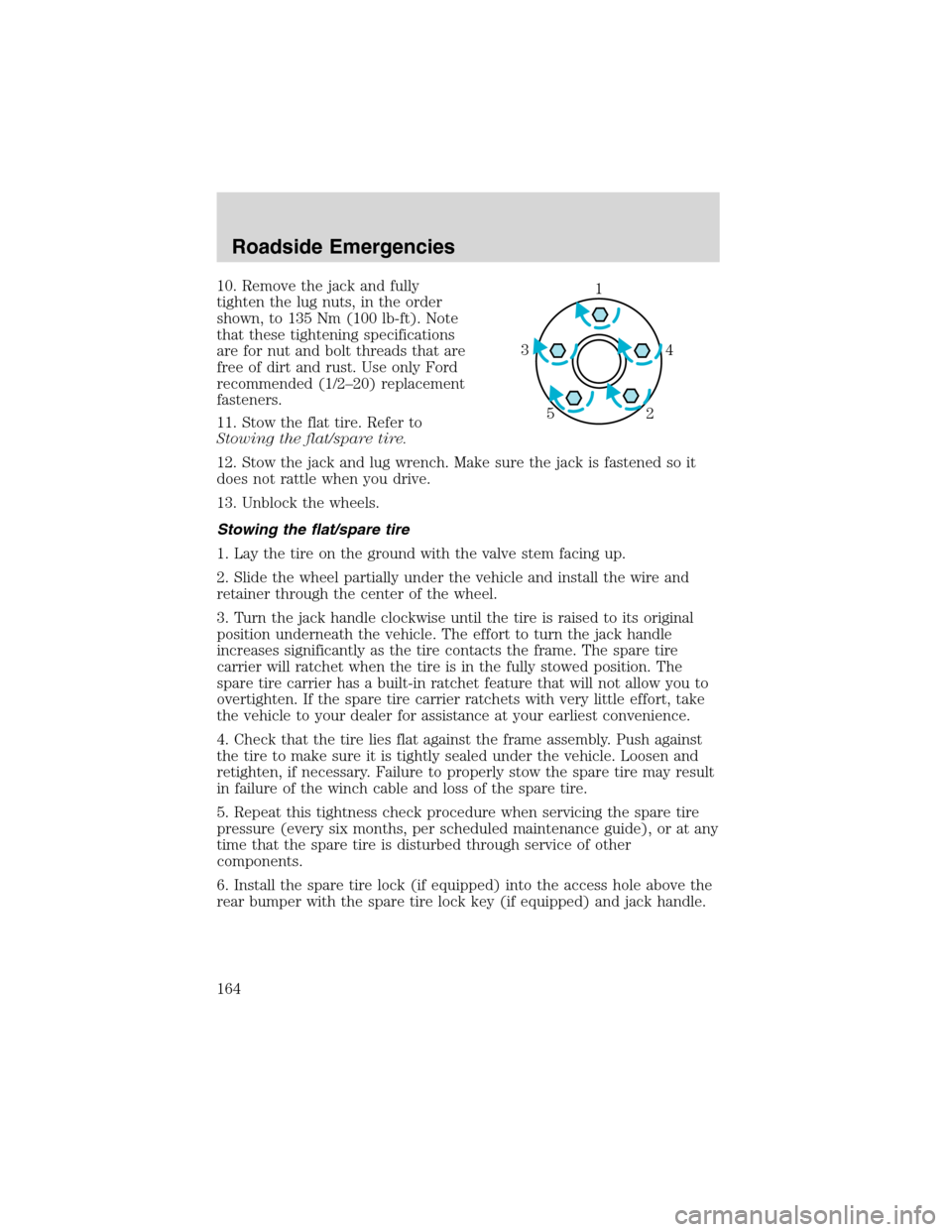
10. Remove the jack and fully
tighten the lug nuts, in the order
shown, to 135 Nm (100 lb-ft). Note
that these tightening specifications
are for nut and bolt threads that are
free of dirt and rust. Use only Ford
recommended (1/2–20) replacement
fasteners.
11. Stow the flat tire. Refer to
Stowing the flat/spare tire.
12. Stow the jack and lug wrench. Make sure the jack is fastened so it
does not rattle when you drive.
13. Unblock the wheels.
Stowing the flat/spare tire
1. Lay the tire on the ground with the valve stem facing up.
2. Slide the wheel partially under the vehicle and install the wire and
retainer through the center of the wheel.
3. Turn the jack handle clockwise until the tire is raised to its original
position underneath the vehicle. The effort to turn the jack handle
increases significantly as the tire contacts the frame. The spare tire
carrier will ratchet when the tire is in the fully stowed position. The
spare tire carrier has a built-in ratchet feature that will not allow you to
overtighten. If the spare tire carrier ratchets with very little effort, take
the vehicle to your dealer for assistance at your earliest convenience.
4. Check that the tire lies flat against the frame assembly. Push against
the tire to make sure it is tightly sealed under the vehicle. Loosen and
retighten, if necessary. Failure to properly stow the spare tire may result
in failure of the winch cable and loss of the spare tire.
5. Repeat this tightness check procedure when servicing the spare tire
pressure (every six months, per scheduled maintenance guide), or at any
time that the spare tire is disturbed through service of other
components.
6. Install the spare tire lock (if equipped) into the access hole above the
rear bumper with the spare tire lock key (if equipped) and jack handle.1
4 3
2 5
Roadside Emergencies
164
Page 196 of 248
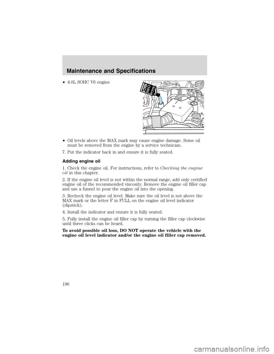
•4.0L SOHC V6 engine
•Oil levels above the MAX mark may cause engine damage. Some oil
must be removed from the engine by a service technician.
7. Put the indicator back in and ensure it is fully seated.
Adding engine oil
1. Check the engine oil. For instructions, refer toChecking the engine
oilin this chapter.
2. If the engine oil level is not within the normal range, add only certified
engine oil of the recommended viscosity. Remove the engine oil filler cap
and use a funnel to pour the engine oil into the opening.
3. Recheck the engine oil level. Make sure the oil level is not above the
MAX mark or the letter F in FULL on the engine oil level indicator
(dipstick).
4. Install the indicator and ensure it is fully seated.
5. Fully install the engine oil filler cap by turning the filler cap clockwise
until three clicks can be heard.
To avoid possible oil loss, DO NOT operate the vehicle with the
engine oil level indicator and/or the engine oil filler cap removed.
Maintenance and Specifications
196
Page 200 of 248
•The vehicle may need to be driven to relearn the idle and fuel trim
strategy.
•If you do not allow the engine to relearn its idle trim, the idle
quality of your vehicle may be adversely affected until the idle
trim is eventually relearned.
When the battery is disconnected or a new battery installed, the
transmission must relearn its adaptive strategy. As a result of this, the
transmission may shift firmly. This operation is considered normal and
will not affect function or durability of the transmission. Over time the
adaptive learning process will fully update transmission operation to its
optimum shift feel.
If the battery has been disconnected or a new battery has been installed,
the clock and the preset radio stations must be reset once the battery is
reconnected.
•Always dispose of automotive
batteries in a responsible manner.
Follow your local authorized
standards for disposal. Call your
local authorized recycling center
to find out more about recycling
automotive batteries.
ENGINE COOLANT
Checking engine coolant
The concentration and level of engine coolant should be checked at the
mileage intervals listed in the scheduled maintenance guide. The coolant
concentration should be maintained at 50/50 coolant and distilled water,
which equates to a freeze point of -36°C (-34°F). Coolant concentration
testing is possible with a hydrometer or antifreeze tester (such as the
Rotunda Battery and Antifreeze Tester, 014–R1060). The level of coolant
should be maintained at the“cold full”of“cold fill range”level in the
coolant reservoir. If the level falls below, add coolant per the instructions
in theAdding Engine Coolantsection.
LEAD
RETURN
RECYCLE
Maintenance and Specifications
200
Page 203 of 248
CXC-209 (Canada), meeting Ford specification WSS-M97B44–D
with the factory-filled coolant.Mixing Motorcraft Speciality Orange
Engine Coolant or any orange-colored extended life product with your
factory filled coolant can result in degraded corrosion protection.
•A large amount of water without engine coolant may be added, in case
of emergency, to reach a vehicle service location. In this instance, the
cooling system must be drained and refilled with a 50/50 mixture of
engine coolant and distilled water as soon as possible. Water alone
(without engine coolant) can cause engine damage from corrosion,
overheating or freezing.
•Do not use alcohol, methanol, brine or any engine coolants
mixed with alcohol or methanol antifreeze (coolant).Alcohol
and other liquids can cause engine damage from overheating or
freezing.
•Do not add extra inhibitors or additives to the coolant.These
can be harmful and compromise the corrosion protection of the engine
coolant.
•Do not mix with recycled coolant unless from a Ford-approved
recycling process (seeUse of Recycled engine coolantsection).
For vehicles with overflow coolant systems with a non-pressurized cap
on the coolant recovery system, add coolant to the coolant recovery
reservoir when the engine is cool. Add the proper mixture of coolant and
water to the“cold full”level. For all other vehicles, which have a coolant
degas system with a pressurized cap, or if it is necessary to remove the
coolant pressure relief cap on the radiator of a vehicle with an overflow
system, follow these steps to add engine coolant.
To reduce the risk of personal injury, make sure the engine is
cool before unscrewing the coolant pressure relief cap. The
cooling system is under pressure; steam and hot liquid can come out
forcefully when the cap is loosened slightly.
1. Before you begin, turn the engine off and let it cool.
2. When the engine is cool, wrap a thick cloth around the coolant
pressure relief cap on the coolant reservoir (an opaque plastic bottle).
Slowly turn cap counterclockwise (left) until pressure begins to release.
3. Step back while the pressure releases.
4. When you are sure that all the pressure has been released, use the
cloth to turn it counterclockwise and remove the cap.
Maintenance and Specifications
203
Page 208 of 248
When refueling always shut the engine off and never allow
sparks or open flames near the filler neck. Never smoke while
refueling. Fuel vapor is extremely hazardous under certain conditions.
Care should be taken to avoid inhaling excess fumes.
The flow of fuel through a fuel pump nozzle can produce static
electricity, which can cause a fire if fuel is pumped into an
ungrounded fuel container.
Use the following guidelines to avoid static build-up when filling an
ungrounded fuel container:
•Place approved fuel container on the ground.
•DO NOT fill a fuel container while it is in the vehicle (including the
cargo area).
•Keep the fuel pump nozzle in contact with the fuel container while
filling.
•DO NOT use a device that would hold the fuel pump handle in the fill
position.
Fuel Filler Cap
Your fuel tank filler cap has an indexed design with a 1/8 turn on/off
feature.
When fueling your vehicle:
1. Turn the engine off.
2. Carefully turn the filler cap counterclockwise 1/8 of a turn until it
stops.
3. Pull to remove the cap from the fuel filler pipe.
4. To install the cap, align the tabs on the cap with the notches on the
filler pipe.
5. Turn the filler cap clockwise 1/8 of a turn until it stops.
“Check Fuel Cap”illuminates when the ignition is turned to the ON
position to ensure your bulb is working. When this light turns on, check
the fuel filler cap. Continuing to operate the vehicle with the Check Fuel
Cap light on, can activate the Service Engine Soon warning. When the
fuel filler cap is properly re-installed, the light(s) will turn off after a
period of normal driving.It may take a long period of time for the
system to detect an improperly installed fuel filler cap.
Maintenance and Specifications
208