key FORD SIERRA 1982 1.G Braking System Workshop Manual
[x] Cancel search | Manufacturer: FORD, Model Year: 1982, Model line: SIERRA, Model: FORD SIERRA 1982 1.GPages: 22, PDF Size: 1.11 MB
Page 4 of 22

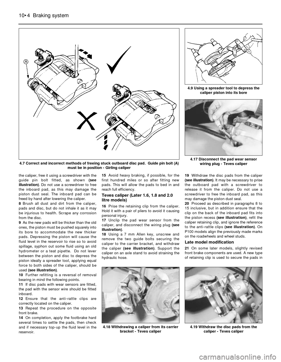
the caliper, free it using a screwdriver with the
guide pin bolt fitted, as shown (see
illustration). Do not use a screwdriver to free
the inboard pad, as this may damage the
piston dust seal. The inboard pad can be
freed by hand after lowering the caliper.
8Brush all dust and dirt from the caliper,
pads and disc, but do not inhale it as it may
be injurious to health. Scrape any corrosion
from the disc.
9As the new pads will be thicker than the old
ones, the piston must be pushed squarely into
its bore to accommodate the new thicker
pads. Depressing the piston will cause the
fluid level in the reservoir to rise so to avoid
spillage, syphon out some fluid using an old
hydrometer or a teat pipette. Do not lever
between the piston and disc to depress the
piston ideally a spreader tool, applying equal
force to both sides of the caliper, should be
used (see illustration).
10Further refitting is a reversal of removal
bearing in mind the following points.
11If disc pads with wear sensors are fitted,
the pad with the sensor wire should be fitted
inboard.
12Ensure that the anti-rattle clips are
correctly located on the caliper.
13Repeat the procedure on the opposite
front brake.
14On completion, apply the footbrake hard
several times to settle the pads, then check
and if necessary top-up the fluid level in the
reservoir. 15Avoid heavy braking, if possible, for the
first hundred miles or so after fitting new
pads. This will allow the pads to bed in and
reach full efficiency.
Teves caliper (Later 1.6, 1.8 and 2.0
litre models)
16Prise the retaining clip from the caliper.
Hold it with a pair of pliers to avoid it causing
personal injury.
17Unclip the pad wear sensor from the
caliper, and disconnect the wiring plug (see
illustration).
18Using a 7 mm Allen key, unscrew and
remove the two guide bolts securing the
caliper to the carrier bracket, and withdraw
the caliper (see illustration). Support the
caliper on an axle stand to avoid straining the
hydraulic hose.19Withdraw the disc pads from the caliper
(see illustration). It may be necessary to prise
the outboard pad with a screwdriver to
release it from the caliper. Do not use a
screwdriver to free the inboard pad, as this
may damage the piston dust seal.
20Proceed as described in paragraphs 8 to
15 inclusive, but in addition ensure that the
clip on the back of the inboard pad fits into
the piston recess (see illustration), refit the
caliper retaining clip, and ignore the reference
to the anti-rattle clips (see illustration). On
P100 models align the previously made marks
on the roadwheels and wheel studs.
Late model modification
21On some later models, slightly revised
front brake components are used. A new type
of retaining clip is used to secure the pads in
10•4Braking system
4.7 Correct and incorrect methods of freeing stuck outboard disc pad. Guide pin bolt (A)
must be in position - Girling caliper
4.9 Using a spreader tool to depress the
caliper piston into its bore
4.19 Withdraw the disc pads from the
caliper - Teves caliper4.18 Withdrawing a caliper from its carrier
bracket - Teves caliper
4.17 Disconnect the pad wear sensor
wiring plug - Teves caliper
Page 11 of 22

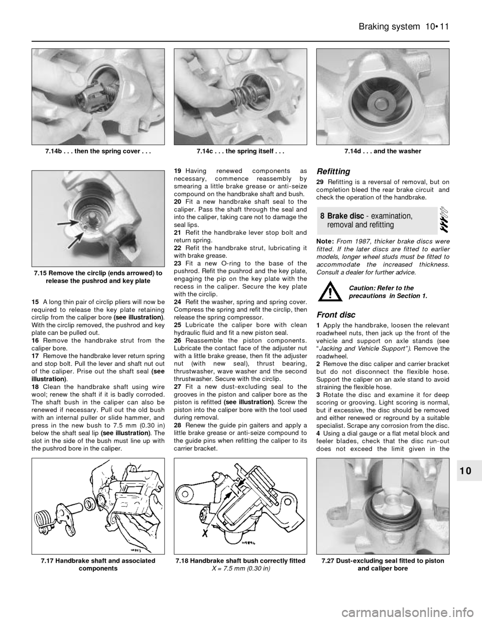
15A long thin pair of circlip pliers will now be
required to release the key plate retaining
circlip from the caliper bore (see illustration).
With the circlip removed, the pushrod and key
plate can be pulled out.
16Remove the handbrake strut from the
caliper bore.
17Remove the handbrake lever return spring
and stop bolt. Pull the lever and shaft nut out
of the caliper. Prise out the shaft seal (see
illustration).
18Clean the handbrake shaft using wire
wool; renew the shaft if it is badly corroded.
The shaft bush in the caliper can also be
renewed if necessary. Pull out the old bush
with an internal puller or slide hammer, and
press in the new bush to 7.5 mm (0.30 in)
below the shaft seal lip (see illustration). The
slot in the side of the bush must line up with
the pushrod bore in the caliper.19Having renewed components as
necessary, commence reassembly by
smearing a little brake grease or anti-seize
compound on the handbrake shaft and bush.
20Fit a new handbrake shaft seal to the
caliper. Pass the shaft through the seal and
into the caliper, taking care not to damage the
seal lips.
21Refit the handbrake lever stop bolt and
return spring.
22Refit the handbrake strut, lubricating it
with brake grease.
23Fit a new O-ring to the base of the
pushrod. Refit the pushrod and the key plate,
engaging the pip on the key plate with the
recess in the caliper. Secure the key plate
with the circlip.
24Refit the washer, spring and spring cover.
Compress the spring and refit the circlip, then
release the spring compressor.
25Lubricate the caliper bore with clean
hydraulic fluid and fit a new piston seal.
26Reassemble the piston components.
Lubricate the contact face of the adjuster nut
with a little brake grease, then fit the adjuster
nut (with new seal), thrust bearing,
thrustwasher, wave washer and the second
thrustwasher. Secure with the circlip.
27Fit a new dust-excluding seal to the
grooves in the piston and caliper bore as the
piston is refitted (see illustration). Screw the
piston into the caliper bore with the tool used
during removal.
28Renew the guide pin gaiters and apply a
little brake grease or anti-seize compound to
the guide pins when refitting the caliper to its
carrier bracket.
Refitting
29Refitting is a reversal of removal, but on
completion bleed the rear brake circuit and
check the operation of the handbrake.
Note: From 1987, thicker brake discs were
fitted. If the later discs are fitted to earlier
models, longer wheel studs must be fitted to
accommodate the increased thickness.
Consult a dealer for further advice.
Front disc
1Apply the handbrake, loosen the relevant
roadwheel nuts, then jack up the front of the
vehicle and support on axle stands (see
“Jacking and Vehicle Support”). Remove the
roadwheel.
2Remove the disc caliper and carrier bracket
but do not disconnect the flexible hose.
Support the caliper on an axle stand to avoid
straining the flexible hose.
3Rotate the disc and examine it for deep
scoring or grooving. Light scoring is normal,
but if excessive, the disc should be removed
and either renewed or reground by a suitable
specialist. Scrape any corrosion from the disc.
4Using a dial gauge or a flat metal block and
feeler blades, check that the disc run-out
does not exceed the limit given in the
8Brake disc - examination,
removal and refitting
Braking system 10•11
10
7.14d . . . and the washer
7.27 Dust-excluding seal fitted to piston
and caliper bore7.18 Handbrake shaft bush correctly fitted
X = 7.5 mm (0.30 in)7.17 Handbrake shaft and associated
components
7.15 Remove the circlip (ends arrowed) to
release the pushrod and key plate
7.14c . . . the spring itself . . .7.14b . . . then the spring cover . . .
Caution: Refer to the
precautions in Section 1.
Page 16 of 22

7Remove the clip from the hydraulic unit
pushrod on the brake pedal.
8With an assistant supporting the hydraulic
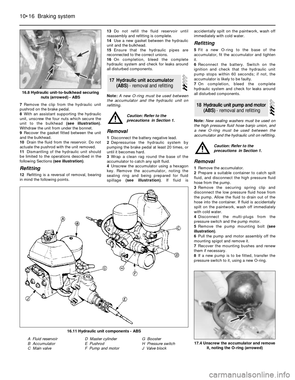
unit, unscrew the four nuts which secure the
unit to the bulkhead (see illustration).
Withdraw the unit from under the bonnet.
9Recover the gasket fitted between the unit
and the bulkhead.
10Drain the fluid from the reservoir. Do not
actuate the pushrod with the unit removed.
11Dismantling of the hydraulic unit should
be limited to the operations described in the
following Sections (see illustration).
Refitting
12Refitting is a reversal of removal, bearing
in mind the following points.13Do not refill the fluid reservoir until
reassembly and refitting is complete.
14Use a new gasket between the hydraulic
unit and the bulkhead.
15Ensure that the hydraulic pipes are
reconnected to the correct unions.
16On completion, bleed the complete
hydraulic system and check for leaks around
all disturbed components.
Note: A new O-ring must be used between
the accumulator and the hydraulic unit on
refitting.
Removal
1Disconnect the battery negative lead.
2Depressurise the hydraulic system by
pumping the brake pedal at least 20 times, or
until it becomes hard.
3Wrap a clean rag round the base of the
accumulator to catch any spilt fluid.
4Unscrew the accumulator using a hexagon
key. Remove the accumulator, noting the
sealing ring and being prepared for fluid
spillage (see illustration). If fluid isaccidentally spilt on the paintwork, wash off
immediately with cold water.
Refitting
5Fit a new O-ring to the base of the
accumulator, fit the accumulator and tighten
it.
6Reconnect the battery. Switch on the
ignition and check that the hydraulic unit
pump stops within 60 seconds; if not, the
accumulator is likely to be faulty.
7On completion, bleed the complete
hydraulic system and check for leaks around
all disturbed components.
Note: New sealing washers must be used on
the high pressure fluid hose banjo union, and
a new O-ring must be used between the
accumulator and the hydraulic unit on refitting.
Removal
1Remove the accumulator.
2Prepare a suitable container to catch spilt
fluid, and disconnect the high pressure fluid
hose from the pump.
3Remove the securing spring clip and
disconnect the low pressure fluid hose from
the pump. Allow the fluid to drain out of the
hose into the container. If fluid is accidentally
spilt on the paintwork, wash off immediately
with cold water.
4Disconnect the multi-plugs from the
pressure switch and the pump motor.
5Remove the pump mounting bolt (see
illustration).
6Pull the pump and motor assembly off the
mounting spigot and remove it.
7Recover the mounting bushes and renew
them if necessary.
8If a new pump is to be fitted, transfer the
pressure switch to it, using a new O-ring.
18Hydraulic unit pump and motor
(ABS) - removal and refitting
17Hydraulic unit accumulator
(ABS) - removal and refitting
10•16Braking system
16.8 Hydraulic unit-to-bulkhead securing
nuts (arrowed) - ABS
17.4 Unscrew the accumulator and remove
it, noting the O-ring (arrowed)
16.11 Hydraulic unit components - ABS
A Fluid reservoir
B Accumulator
C Main valveD Master cylinder
E Pushrod
F Pump and motorG Booster
H Pressure switch
J Valve block
Caution: Refer to the
precautions in Section 1.
Caution: Refer to the
precautions in Section 1.