fuel cap release FORD SIERRA 1982 1.G Engine Electrical Systems Workshop Manual
[x] Cancel search | Manufacturer: FORD, Model Year: 1982, Model line: SIERRA, Model: FORD SIERRA 1982 1.GPages: 24, PDF Size: 0.93 MB
Page 9 of 24

8Connect the voltmeter between the battery
positive terminal and the terminal on the
starter motor. With the coil low tension lead
disconnected operate the starter for two or
three seconds. Battery voltage should be
indicated initially, then dropping to less than 1
volt. If the reading is more than 1 volt, there is
a high resistance in the wiring from the battery
to the starter and the check in paragraph 9
should be made. If the reading is less than 1
volt proceed to paragraph 10.
9Connect the voltmeter between the two
main solenoid terminals and operate the
starter for two or three seconds. Battery
voltage should be indicated initially, then
dropping to less than 0.5 volt. If the reading is
more than 0.5 volt, the ignition switch and
connections may be faulty.
10Connect the voltmeter between the
battery negative terminal and the starter
motor body, and operate the starter for two or
three seconds. A reading of less than 0.5 volt
should be recorded. If the reading is more
than 0.5 volt, there is a fault in the earth
circuit, and the earth connections to the
battery and body should be checked.
Bosch long frame and JF, and
Cajavec types
1With the starter motor removed from the
vehicle and cleaned, grip the unit in a vice
fitted with soft jaw protectors.
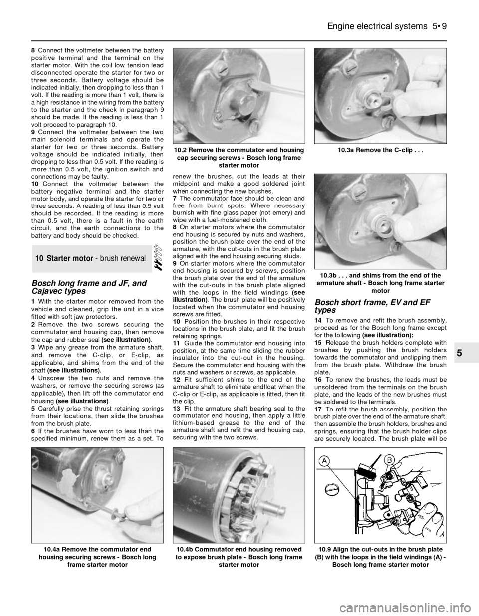
2Remove the two screws securing the
commutator end housing cap, then remove
the cap and rubber seal (see illustration).
3Wipe any grease from the armature shaft,
and remove the C-clip, or E-clip, as
applicable, and shims from the end of the
shaft (see illustrations).
4Unscrew the two nuts and remove the
washers, or remove the securing screws (as
applicable), then lift off the commutator end
housing (see illustrations).
5Carefully prise the thrust retaining springs
from their locations, then slide the brushes
from the brush plate.
6If the brushes have worn to less than the
specified minimum, renew them as a set. Torenew the brushes, cut the leads at their
midpoint and make a good soldered joint
when connecting the new brushes.
7The commutator face should be clean and
free from burnt spots. Where necessary
burnish with fine glass paper (not emery) and
wipe with a fuel-moistened cloth.
8On starter motors where the commutator
end housing is secured by nuts and washers,
position the brush plate over the end of the
armature, with the cut-outs in the brush plate
aligned with the end housing securing studs.
9On starter motors where the commutator
end housing is secured by screws, position
the brush plate over the end of the armature
with the cut-outs in the brush plate aligned
with the loops in the field windings (see
illustration). The brush plate will be positively
located when the commutator end housing
screws are fitted.
10Position the brushes in their respective
locations in the brush plate, and fit the brush
retaining springs.
11Guide the commutator end housing into
position, at the same time sliding the rubber
insulator into the cut-out in the housing.
Secure the commutator end housing with the
nuts and washers or screws, as applicable.
12Fit sufficient shims to the end of the
armature shaft to eliminate endfloat when the
C-clip or E-clip, as applicable is fitted, then fit
the clip.
13Fit the armature shaft bearing seal to the
commutator end housing, then apply a little
lithium-based grease to the end of the
armature shaft and refit the end housing cap,
securing with the two screws.Bosch short frame, EV and EF
types
14To remove and refit the brush assembly,
proceed as for the Bosch long frame except
for the following(see illustration):
15Release the brush holders complete with
brushes by pushing the brush holders
towards the commutator and unclipping them
from the brush plate. Withdraw the brush
plate.
16To renew the brushes, the leads must be
unsoldered from the terminals on the brush
plate, and the leads of the new brushes must
be soldered to the terminals.
17To refit the brush assembly, position the
brush plate over the end of the armature shaft,
then assemble the brush holders, brushes and
springs, ensuring that the brush holder clips
are securely located. The brush plate will be
10Starter motor - brush renewal
Engine electrical systems 5•9
5
10.3b . . . and shims from the end of the
armature shaft - Bosch long frame starter
motor
10.9 Align the cut-outs in the brush plate
(B) with the loops in the field windings (A) -
Bosch long frame starter motor10.4b Commutator end housing removed
to expose brush plate - Bosch long frame
starter motor10.4a Remove the commutator end
housing securing screws - Bosch long
frame starter motor
10.3a Remove the C-clip . . .10.2 Remove the commutator end housing
cap securing screws - Bosch long frame
starter motor
Page 14 of 24

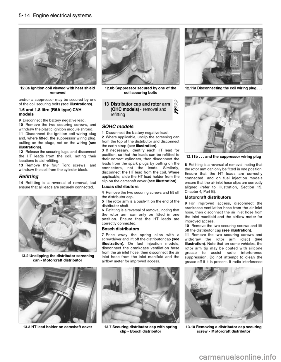
and/or a suppressor may be secured by one
of the coil securing bolts (see illustrations).
1.6 and 1.8 litre (R6A type) CVH
models
9Disconnect the battery negative lead.
10Remove the two securing screws, and
withdraw the plastic ignition module shroud.
11Disconnect the ignition coil wiring plug
and, where fitted, the suppressor wiring plug,
pulling on the plugs, not on the wiring (see
illustrations).
12Release the securing lugs, and disconnect
the HT leads from the coil, noting their
locations to aid refitting.
13Remove the four Torx screws, and
withdraw the coil from the cylinder block.
Refitting
14Refitting is a reversal of removal, but
ensure that all leads are securely connected.
SOHC models
1Disconnect the battery negative lead.
2Where applicable, unclip the screening can
from the top of the distributor and disconnect
the earth strap (see illustration).
3If necessary, identify each HT lead for
position, so that the leads can be refitted to
their correct cylinders, then disconnect the
leads from the spark plugs by pulling on the
connectors, not the leads. Similarly,
disconnect the HT lead from the coil. Where
applicable, slide the HT lead holder from the
clip on the camshaft cover (see illustration).
Lucas distributors
4Remove the two securing screws and lift off
the distributor cap.
5The rotor arm is a push-fit on the end of the
distributor shaft.
6Refitting is a reversal of removal, noting that
the rotor arm can only be fitted in one
position. Ensure that the HT leads are
correctly connected.
Bosch distributors
7Prise away the spring clips with a
screwdriver and lift off the distributor cap(see
illustration).On fuel injection models,
disconnect the crankcase ventilation hose
from the air inlet hose, then disconnect the air
inlet hose from the inlet manifold and the
airflow meter for improved access. 8Refitting is a reversal of removal, noting that
the rotor arm can only be fitted in one position.
Ensure that the HT leads are correctly
connected, and on fuel injection models
ensure that the air inlet hose clips are correctly
aligned (refer to illustration, Section 15,
Chapter 4, PartB).
Motorcraft distributors
9For improved access, disconnect the
crankcase ventilation hose from the air inlet
hose, then disconnect the air inlet hose from
the inlet manifold and the airflow meter for
improved access.
10Remove the two securing screws and lift
off the distributor cap (see illustration).
11Remove the two securing screws and
withdraw the rotor arm (disc) (see
illustration). Note that on some vehicles, the
rotor arm tip may be coated with silicone
grease to assist radio interference
suppression. Do not attempt to clean the
grease off if it is present. If radio interference
13Distributor cap and rotor arm
(OHC models) - removal and
refitting
5•14Engine electrical systems
12.8a Ignition coil viewed with heat shield
removed12.11a Disconnecting the coil wiring plug . . .
13.10 Removing a distributor cap securing
screw - Motorcraft distributor13.7 Securing distributor cap with spring
clip - Bosch distributor13.3 HT lead holder on camshaft cover
13.2 Unclipping the distributor screening
can - Motorcraft distributor
12.11b . . . and the suppressor wiring plug
12.8b Suppressor secured by one of the
coil securing bolts