heating FORD SIERRA 1982 1.G SOHC Engines Workshop Manual
[x] Cancel search | Manufacturer: FORD, Model Year: 1982, Model line: SIERRA, Model: FORD SIERRA 1982 1.GPages: 24, PDF Size: 1.03 MB
Page 18 of 24

Note: A new gasket should be used when
refitting the auxiliary shaft cover (see text).
Removal
1Remove the timing belt and the auxiliary
shaft sprocket.
2Remove the distributor.
3Remove the mechanical fuel pump and
operating pushrod (where applicable).
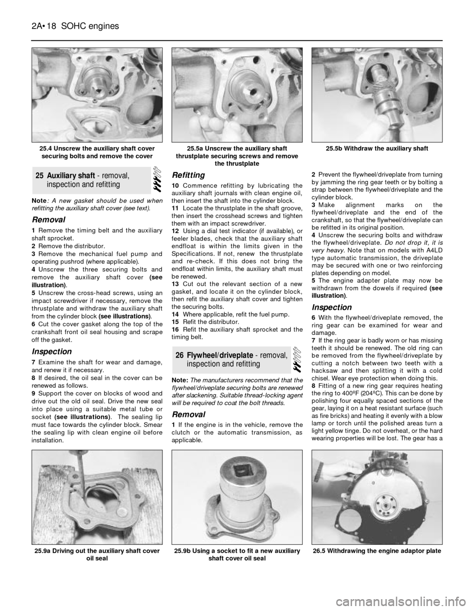
4Unscrew the three securing bolts and
remove the auxiliary shaft cover (see
illustration).
5Unscrew the cross-head screws, using an
impact screwdriver if necessary, remove the
thrustplate and withdraw the auxiliary shaft
from the cylinder block (see illustrations).
6Cut the cover gasket along the top of the
crankshaft front oil seal housing and scrape
off the gasket.
Inspection
7Examine the shaft for wear and damage,
and renew it if necessary.
8If desired, the oil seal in the cover can be
renewed as follows.
9Support the cover on blocks of wood and
drive out the old oil seal. Drive the new seal
into place using a suitable metal tube or
socket (see illustrations). The sealing lip
must face towards the cylinder block. Smear
the sealing lip with clean engine oil before
installation.
Refitting
10Commence refitting by lubricating the
auxiliary shaft journals with clean engine oil,
then insert the shaft into the cylinder block.
11Locate the thrustplate in the shaft groove,
then insert the crosshead screws and tighten
them with an impact screwdriver.
12Using a dial test indicator (if available), or
feelerblades, check that the auxiliary shaft
endfloat is within the limits given in the
Specifications. If not, renew the thrustplate
and re-check. If this does not bring the
endfloat within limits, the auxiliary shaft must
be renewed.
13Cut out the relevant section of a new
gasket, and locate it on the cylinder block,
then refit the auxiliary shaft cover and tighten
the securing bolts.
14Where applicable, refit the fuel pump.
15Refit the distributor.
16Refit the auxiliary shaft sprocket and the
timing belt.
Note: The manufacturers recommend that the
flywheel/driveplate securing bolts are renewed
after slackening. Suitable thread-locking agent
will be required to coat the bolt threads.
Removal
1If the engine is in the vehicle, remove the
clutch or the automatic transmission, as
applicable.2Prevent the flywheel/driveplate from turning
by jamming the ring gear teeth or by bolting a
strap between the flywheel/driveplate and the
cylinder block.
3Make alignment marks on the
flywheel/driveplate and the end of the
crankshaft, so that the flywheel/driveplate can
be refitted in its original position.
4Unscrew the securing bolts and withdraw
the flywheel/driveplate. Do not drop it, it is
very heavy. Note that on models with A4LD
type automatic transmission, the driveplate
may be secured with one or two reinforcing
plates depending on model.
5The engine adapter plate may now be
withdrawn from the dowels if required (see
illustration).
Inspection
6With the flywheel/driveplate removed, the
ring gear can be examined for wear and
damage.
7If the ring gear is badly worn or has missing
teeth it should be renewed. The old ring can
be removed from the flywheel/driveplate by
cutting a notch between two teeth with a
hacksaw and then splitting it with a cold
chisel. Wear eye protection when doing this.
8Fitting of a new ring gear requires heating
the ring to 400¼F (204¼C). This can be done by
polishing four equally spaced sections of the
gear, laying it on a heat resistant surface (such
as fire bricks) and heating it evenly with a blow
lamp or torch until the polished areas turn a
light yellow tinge. Do not overheat, or the hard
wearing properties will be lost. The gear has a
26Flywheel/driveplate - removal,
inspection and refitting
25Auxiliary shaft - removal,
inspection and refitting
2A¥18SOHC engines
25.4 Unscrew the auxiliary shaft cover
securing bolts and remove the cover25.5b Withdraw the auxiliary shaft
26.5 Withdrawing the engine adaptor plate25.9b Using a socket to fit a new auxiliary
shaft cover oil seal25.9a Driving out the auxiliary shaft cover
oil seal
25.5a Unscrew the auxiliary shaft
thrustplate securing screws and remove
the thrustplate