spark plugs FORD SIERRA 1982 1.G SOHC Engines Workshop Manual
[x] Cancel search | Manufacturer: FORD, Model Year: 1982, Model line: SIERRA, Model: FORD SIERRA 1982 1.GPages: 24, PDF Size: 1.03 MB
Page 7 of 24

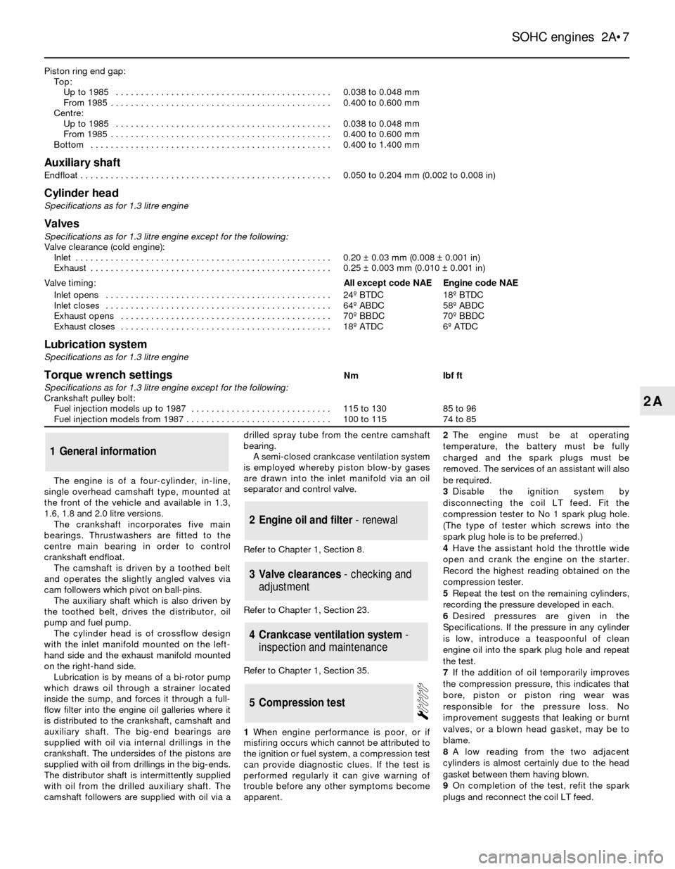
Piston ring end gap:
Top:
Up to 1985 . . . . . . . . . . . . . . . . . . . . . . . . . . . . . . . . . . . . . . . . . . .0.038 to 0.048 mm
From 1985 . . . . . . . . . . . . . . . . . . . . . . . . . . . . . . . . . . . . . . . . . . . .0.400 to 0.600 mm
Centre:
Up to 1985 . . . . . . . . . . . . . . . . . . . . . . . . . . . . . . . . . . . . . . . . . . .0.038 to 0.048 mm
From 1985 . . . . . . . . . . . . . . . . . . . . . . . . . . . . . . . . . . . . . . . . . . . .0.400 to 0.600 mm
Bottom . . . . . . . . . . . . . . . . . . . . . . . . . . . . . . . . . . . . . . . . . . . . . . . .0.400 to 1.400 mm
Auxiliary shaft
Endfloat . . . . . . . . . . . . . . . . . . . . . . . . . . . . . . . . . . . . . . . . . . . . . . . . . .0.050 to 0.204 mm (0.002 to 0.008 in)
Cylinder head
Specifications as for 1.3 litre engine
Valves
Specifications as for 1.3 litre engine except for the following:
Valve clearance (cold engine):
Inlet . . . . . . . . . . . . . . . . . . . . . . . . . . . . . . . . . . . . . . . . . . . . . . . . . . .0.20 ±0.03 mm (0.008 ±0.001 in)
Exhaust . . . . . . . . . . . . . . . . . . . . . . . . . . . . . . . . . . . . . . . . . . . . . . . .0.25 ±0.003 mm (0.010 ±0.001 in)
Valve timing:All except code NAEEngine code NAE
Inlet opens . . . . . . . . . . . . . . . . . . . . . . . . . . . . . . . . . . . . . . . . . . . . .24¼ BTDC18¼ BTDC
Inlet closes . . . . . . . . . . . . . . . . . . . . . . . . . . . . . . . . . . . . . . . . . . . . .64¼ ABDC58¼ ABDC
Exhaust opens . . . . . . . . . . . . . . . . . . . . . . . . . . . . . . . . . . . . . . . . . .70¼ BBDC70¼ BBDC
Exhaust closes . . . . . . . . . . . . . . . . . . . . . . . . . . . . . . . . . . . . . . . . . .18¼ ATDC6¼ ATDC
Lubrication system
Specifications as for 1.3 litre engine
Torque wrench settingsNmlbf ft
Specifications as for 1.3 litre engine except for the following:
Crankshaft pulley bolt:
Fuel injection models up to 1987 . . . . . . . . . . . . . . . . . . . . . . . . . . . .115 to 13085 to 96
Fuel injection models from 1987 . . . . . . . . . . . . . . . . . . . . . . . . . . . . .100 to 11574 to 85
SOHC engines 2A¥7
2A
The engine is of a four-cylinder, in-line,
single overhead camshaft type, mounted at
the front of the vehicle and available in 1.3,
1.6, 1.8 and 2.0 litre versions.
The crankshaft incorporates five main
bearings. Thrustwashers are fitted to the
centre main bearing in order to control
crankshaft endfloat.
The camshaft is driven by a toothed belt
and operates the slightly angled valves via
cam followers which pivot on ball-pins.
The auxiliary shaft which is also driven by
the toothed belt, drives the distributor, oil
pump and fuel pump.
The cylinder head is of crossflow design
with the inlet manifold mounted on the left-
hand side and the exhaust manifold mounted
on the right-hand side.
Lubrication is by means of a bi-rotor pump
which draws oil through a strainer located
inside the sump, and forces it through a full-
flow filter into the engine oil galleries where it
is distributed to the crankshaft, camshaft and
auxiliary shaft. The big-end bearings are
supplied with oil via internal drillings in the
crankshaft. The undersides of the pistons are
supplied with oil from drillings in the big-ends.
The distributor shaft is intermittently supplied
with oil from the drilled auxiliary shaft. The
camshaft followers are supplied with oil via adrilled spray tube from the centre camshaft
bearing.
A semi-closed crankcase ventilation system
is employed whereby piston blow-by gases
are drawn into the inlet manifold via an oil
separator and control valve.
Refer to Chapter 1, Section 8.
Refer to Chapter 1, Section 23.
Refer to Chapter 1, Section 35.
1When engine performance is poor, or if
misfiring occurs which cannot be attributed to
the ignition or fuel system, a compression test
can provide diagnostic clues. If the test is
performed regularly it can give warning of
trouble before any other symptoms become
apparent.2The engine must be at operating
temperature, the battery must be fully
charged and the spark plugs must be
removed. The services of an assistant will also
be required.
3Disable the ignition system by
disconnecting the coil LT feed. Fit the
compression tester to No 1 spark plug hole.
(The type of tester which screws into the
spark plug hole is to be preferred.)
4Have the assistant hold the throttle wide
open and crank the engine on the starter.
Record the highest reading obtained on the
compression tester.
5Repeat the test on the remaining cylinders,
recording the pressure developed in each.
6Desired pressures are given in the
Specifications. If the pressure in any cylinder
is low, introduce a teaspoonful of clean
engine oil into the spark plug hole and repeat
the test.
7If the addition of oil temporarily improves
the compression pressure, this indicates that
bore, piston or piston ring wear was
responsible for the pressure loss. No
improvement suggests that leaking or burnt
valves, or a blown head gasket, may be to
blame.
8A low reading from the two adjacent
cylinders is almost certainly due to the head
gasket between them having blown.
9On completion of the test, refit the spark
plugs and reconnect the coil LT feed.
5Compression test
4Crankcase ventilation system -
inspection and maintenance
3Valve clearances - checking and
adjustment
2Engine oil and filter - renewal
1General information
Page 14 of 24

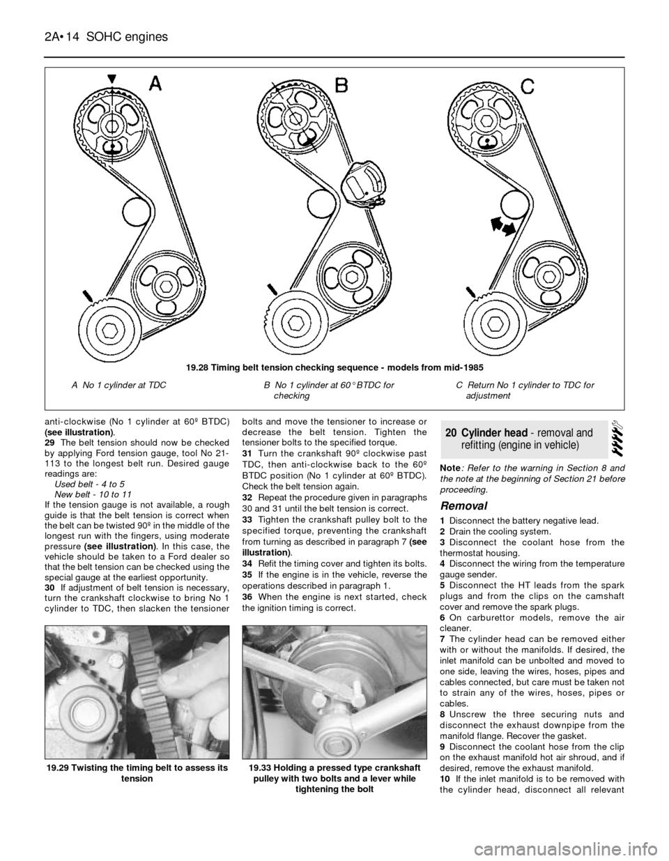
anti-clockwise (No 1 cylinder at 60¼ BTDC)
(see illustration).
29The belt tension should now be checked
by applying Ford tension gauge, tool No 21-
113 to the longest belt run. Desired gauge
readings are:
Used belt - 4 to 5
New belt - 10 to 11
If the tension gauge is not available, a rough
guide is that the belt tension is correct when
the belt can be twisted 90¼ in the middle of the
longest run with the fingers, using moderate
pressure (see illustration). In this case, the
vehicle should be taken to a Ford dealer so
that the belt tension can be checked using the
special gauge at the earliest opportunity.
30If adjustment of belt tension is necessary,
turn the crankshaft clockwise to bring No 1
cylinder to TDC, then slacken the tensionerbolts and move the tensioner to increase or
decrease the belt tension. Tighten the
tensioner bolts to the specified torque.
31Turn the crankshaft 90¼ clockwise past
TDC, then anti-clockwise back to the 60¼
BTDC position (No 1 cylinder at 60¼ BTDC).
Check the belt tension again.
32Repeat the procedure given in paragraphs
30 and 31 until the belt tension is correct.
33Tighten the crankshaft pulley bolt to the
specified torque, preventing the crankshaft
from turning as described in paragraph 7 (see
illustration).
34Refit the timing cover and tighten its bolts.
35If the engine is in the vehicle, reverse the
operations described in paragraph 1.
36When the engine is next started, check
the ignition timing is correct.Note: Refer to the warning in Section 8 and
the note at the beginning of Section 21 before
proceeding.
Removal
1Disconnect the battery negative lead.
2Drain the cooling system.
3Disconnect the coolant hose from the
thermostat housing.
4Disconnect the wiring from the temperature
gauge sender.
5Disconnect the HT leads from the spark
plugs and from the clips on the camshaft
cover and remove the spark plugs.
6On carburettor models, remove the air
cleaner.
7The cylinder head can be removed either
with or without the manifolds. If desired, the
inlet manifold can be unbolted and moved to
one side, leaving the wires, hoses, pipes and
cables connected, but care must be taken not
to strain any of the wires, hoses, pipes or
cables.
8Unscrew the three securing nuts and
disconnect the exhaust downpipe from the
manifold flange. Recover the gasket.
9Disconnect the coolant hose from the clip
on the exhaust manifold hot air shroud, and if
desired, remove the exhaust manifold.
10If the inlet manifold is to be removed with
the cylinder head, disconnect all relevant
20Cylinder head - removal and
refitting (engine in vehicle)
2A¥14SOHC engines
19.33 Holding a pressed type crankshaft
pulley with two bolts and a lever while
tightening the bolt19.29 Twisting the timing belt to assess its
tension
19.28 Timing belt tension checking sequence - models from mid-1985
A No 1 cylinder at TDCB No 1 cylinder at 60¡BTDC for
checkingC Return No 1 cylinder to TDC for
adjustment
Page 15 of 24

wires, hoses, pipes and cables, otherwise,
unbolt the manifold and move it to one side,
ensuring that it is adequately supported.
11If not already done, unclip any wires and
hoses from the camshaft cover, noting their
locations for use when refitting, and on fuel
injection models unbolt the bracing strut
securing the inlet manifold to the right-hand
side of the cylinder head.
12If desired, remove the thermostat and
housing, and the temperature gauge sender.
13Proceed as described in Section 21 for
cylinder head removal.
Refitting
14With the cylinder head refitted as
described in Section 21, proceed as follows.
15Where applicable, refit the temperature
gauge sender and the thermostat and
housing.
16Refit the manifolds and/or reconnect all
wires, hoses, pipes and cables, as applicable.
17Reconnect the exhaust downpipe to the
manifold, using a new gasket.
18Refit the coolant hose to the clip on the
exhaust manifold hot air shroud.
19Refit the spark plugs and reconnect the
HT leads.
20Reconnect the temperature gauge sender
wiring.
21Reconnect the coolant hoses to the
thermostat housing.
22Fill the cooling system.
23If not already done, refit any hoses and
wires to the camshaft cover, as noted during
removal, and on fuel injection models refit the
inlet manifold bracing strut. If splined type
cylinder head bolts have been used, leave
these operations until the bolts have been
finally tightened after running the engine.
24Refit the air cleaner on carburettor
models.
25Reconnect the battery negative lead.
26If splined type cylinder head bolts have
been used, start the engine and run it at 1000
rpm for 15 minutes, then stop the engine,
remove the air cleaner and the camshaft cover
as described previously, and finally tighten the
cylinder head bolts to the fourth stage (see
Specifications). Refit the camshaft cover on
completion, then refit any hoses and wires,
and on fuel injection models the inlet manifold
bracing strut. Refit the air cleaner.Note: Up to early 1984, splined type cylinder
head bolts were used, and from early 1984,
size T55 Torx bolts were used. Torx type bolts
must always be renewed after slackening. The
two types of bolts are interchangeable, but
only in complete sets - the two types must not
be mixed on the same engine. A suitable
special socket will be required for removal of
the bolts, and a new cylinder head gasket
must be used when refitting.
Removal
1With the manifolds removed, proceed as
follows.
2Remove the timing belt.
3Where applicable, disconnect the breather
hose from the camshaft cover.
4Unscrew the ten securing bolts and remove
the camshaft cover and gasket. Take care not
to lose the spacer plates which fit under the
bolt heads, where applicable.
5Using the relevant special socket, unscrew
the ten cylinder head bolts half a turn at a time
in the reverse order to that shown for
tightening.
6With the bolts removed, lift the cylinder
head from the block. If the cylinder head is
stuck, tap it free with a wooden mallet. Place
the cylinder head on blocks of wood to
prevent damage to the valves.
7Recover the gasket.
Refitting
8Commence refitting as follows.
9With the cylinder head supported on blocks
of wood, check and if necessary adjust thevalve clearances. This work is easier to carry
out on the bench rather than in the vehicle.
10Turn the crankshaft so that No 1 piston is
approximately 20 mm (0.8 in) before TDC.
This precaution will prevent any damage to
open valves.
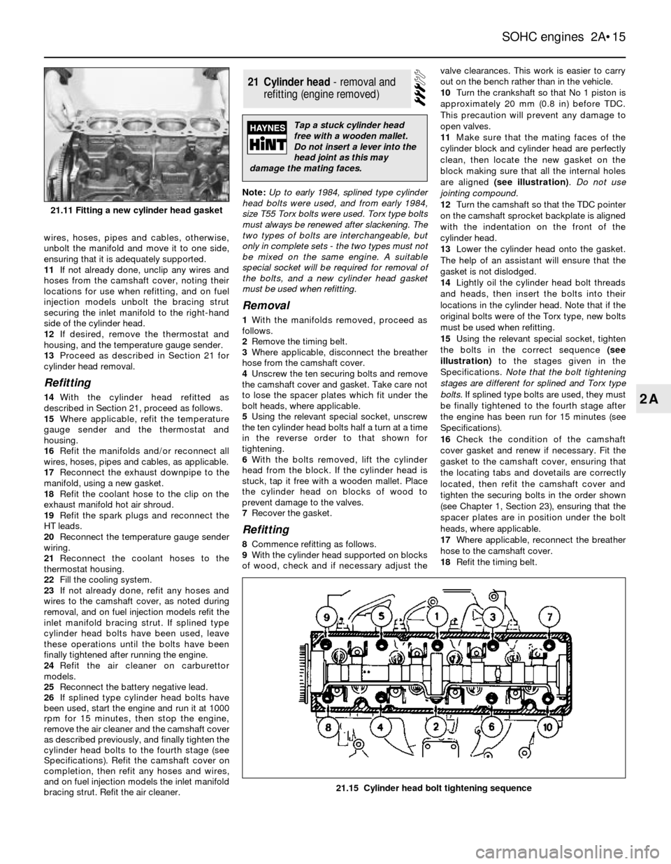
11Make sure that the mating faces of the
cylinder block and cylinder head are perfectly
clean, then locate the new gasket on the
block making sure that all the internal holes
are aligned (see illustration). Do not use
jointing compound.
12Turn the camshaft so that the TDC pointer
on the camshaft sprocket backplate is aligned
with the indentation on the front of the
cylinder head.
13Lower the cylinder head onto the gasket.
The help of an assistant will ensure that the
gasket is not dislodged.
14Lightly oil the cylinder head bolt threads
and heads, then insert the bolts into their
locations in the cylinder head. Note that if the
original bolts were of the Torx type, new bolts
must be used when refitting.
15Using the relevant special socket, tighten
the bolts in the correct sequence (see
illustration)to the stages given in the
Specifications. Note that the bolt tightening
stages are different for splined and Torx type
bolts. If splined type bolts are used, they must
be finally tightened to the fourth stage after
the engine has been run for 15 minutes (see
Specifications).
16Check the condition of the camshaft
cover gasket and renew if necessary. Fit the
gasket to the camshaft cover, ensuring that
the locating tabs and dovetails are correctly
located, then refit the camshaft cover and
tighten the securing bolts in the order shown
(see Chapter 1, Section 23), ensuring that the
spacer plates are in position under the bolt
heads, where applicable.
17Where applicable, reconnect the breather
hose to the camshaft cover.
18Refit the timing belt.
21Cylinder head - removal and
refitting (engine removed)
SOHC engines 2A¥15
2A
21.15 Cylinder head bolt tightening sequence
21.11 Fitting a new cylinder head gasket
Tap a stuck cylinder head
free with a wooden mallet.
Do not insert a lever into the
head joint as this may
damage the mating faces.