window FORD SIERRA 1983 1.G Bodywork And Fittings User Guide
[x] Cancel search | Manufacturer: FORD, Model Year: 1983, Model line: SIERRA, Model: FORD SIERRA 1983 1.GPages: 22, PDF Size: 1.2 MB
Page 14 of 22

New bumpers are supplied without the trim
moulding fitted. Special primer and adhesive
tape are specified by the manufacturer to
retain the moulding: it is suggested that a
Ford dealer is consulted for further details.
A damaged moulding can be removed by
prising it from the bumper using a screwdriver.
Models up to 1987
1With the bonnet raised, remove the four
grille panel securing screws from the top of
the front panel.
2Lift the grille panel from its lower mounting
bushes, and withdraw it from the vehicle.
3Refitting is a reversal of removal, but ensure
that the lower mounting lugs are correctly
located in their bushes.
Models from 1987
4With the bonnet raised, remove the two
grille panel securing screws from the front
face of the panel.
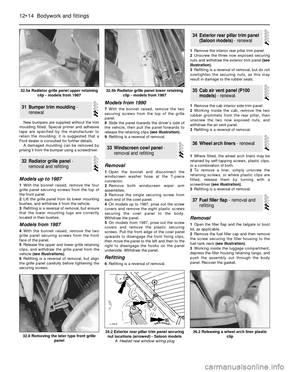
5Release the upper and lower grille retaining
clips, and withdraw the grille panel from the
vehicle (see illustrations).
6Refitting is a reversal of removal, but align
the grille panel carefully before tightening the
securing screws.
Models from 1990
7With the bonnet raised, remove the two
securing screws from the top of the grille
panel.
8Slide the panel towards the driver’s side of
the vehicle, then pull the panel forwards to
release the retaining clips (see illustration).
9Refitting is a reversal of removal.
Removal
1Open the bonnet and disconnect the
windscreen washer hose at the T-piece
connector.
2Remove both windscreen wiper arm
assemblies.
3Remove the single securing screw from
each end of the cowl panel.
4On models up to 1987, prise out the screw
covers and remove the eight plastic screws
securing the cowl panel to the body.
Withdraw the panel.
5On models from 1987, prise out the screw
covers and remove the plastic securing
screws. Pull the front edge of the cowl panel
upwards to disengage the front fixing clips,
then move the panel to the left and then to the
right to disengage the hooks on the panel
underside. Withdraw the panel.
Refitting
6Refitting is a reversal of removal.1Remove the interior rear pillar trim panel.
2Unscrew the three now exposed securing
nuts and withdraw the exterior trim panel (see
illustration).
3Refitting is a reversal of removal, but do not
overtighten the securing nuts, as this may
result in damage to the rubber seals.
1Remove the cab interior side trim panel.
2Working inside the cab, remove the two
rubber grommets from the rear pillar, then
unscrew the two now exposed nuts, and
withdraw the air vent panel.
3Refitting is a reversal of removal.
1Where fitted, the wheel arch liners may be
retained by self-tapping screws, plastic clips,
or a combination of both.
2To remove a liner, simply unscrew the
retaining screws, or where plastic clips are
fitted, release them by turning with a
screwdriver (see illustration).
3Refitting is a reversal of removal.
Removal
1Open the filler flap and the tailgate or boot
lid, as applicable.
2Remove the fuel filler cap and then remove
the screw securing the filler housing to the
fuel tank neck (see illustration).
3Working inside the luggage compartment,
depress the filler housing retaining tangs, and
push the assembly out through the body
panel. Recover the gasket.
37Fuel filler flap - removal and
refitting
36Wheel arch liners - renewal
35Cab air vent panel (P100
models) - renewal
34Exterior rear pillar trim panel
(Saloon models) - renewal
33Windscreen cowl panel -
removal and refitting
32Radiator grille panel -
removal and refitting
31Bumper trim moulding -
renewal
12•14Bodywork and fittings
32.8 Removing the later type front grille
panel36.2 Releasing a wheel arch liner plastic
clip34.2 Exterior rear pillar trim panel securing
nut locations (arrowed) - Saloon models
A Heated rear window wiring plug
32.5b Radiator grille panel lower retaining
clip - models from 198732.5a Radiator grille panel upper retaining
clip - models from 1987
Page 16 of 22

4Unscrew the upper seat belt anchor nut,
noting the fitted positions of any washers and
spacers so that they can be refitted in their
original positions.
5Remove the two securing screws, and
withdraw the upper trim panel.
6Remove the two or three securing screws
as applicable, and withdraw the lower trim
panel, passing the seat belt webbing through
the panel as it is removed.
7Refitting is a reversal of removal.
Rear pillar
Saloon models
8Remove the rear seat cushion.
9Unbolt the lower seat belt anchor.
10On models with fixed rear seats, remove
the backrest.
11On models with folding rear seats, remove
the side cushion.
12Remove the two securing screws from the
base of the pillar trim panel, then pull the trim
panel from the pillar, passing the seat belt
webbing through the panel as it is removed.
13Refitting is a reversal of removal.
Hatchback models
14Remove the rear seat side cushion.
15Remove the rear parcel shelf, and where
applicable unbolt the rear seat belt upper
anchor and spacer.
16On “high specification” models, lift the
seat catch release lever, push out the pin
securing the link rod to the lever and
disconnect the link rod.
17Remove the securing screws from the rear
parcel shelf support (nine screws on models
up to 1987, eight screws from 1987 onwards)
and on “high specification” models remove
the two bolts securing the rear seat catch
assembly to the wheel arch, then withdraw
the catch assembly. Remove the rear parcel
shelf support.
18Remove the five securing screws and
detach the rear pillar trim panel.
19Refitting is a reversal of removal, but
where applicable check the operation of the
rear seat catch on completion.
P100 models
20Remove the cover from the seat belt
upper anchor, then unscrew the anchor,
noting the fitted positions of any washers and
spacers so that they can be refitted in their
original positions.
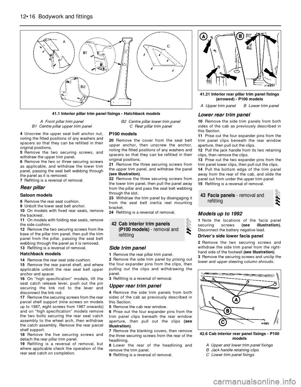
21Remove the three securing screws from
the upper trim panel, and withdraw the panel
(see illustration).
22Remove the three securing screws from
the lower trim panel, then pull the panel away
from the pillar and pass the seat belt webbing
through the slot.
23Withdraw the trim panel by disengaging it
from the seat belt inertia reel mounting
bracket.
24Refitting is a reversal of removal.
Side trim panel
1Remove the rear pillar trim panel.
2Remove the side trim panel by prising out
the four expander pins from the clips, then
pulling out the clips and withdrawing the
panel.
3Refitting is a reversal of removal.
Upper rear trim panel
4Remove the side trim panels from both
sides of the cab as previously described in
this Section.
5Remove the cab rear window.
6Prise out the four expander pins from the
trim panel clips beneath the rear window
aperture, then pull out the clips (see
illustration).
7Remove the blanking covers, then remove
the three securing screws from the rear of the
headlining.
8Lower the rear of the headlining and
remove the trim panel.
9Refitting is a reversal of removal.
Lower rear trim panel
10Remove the side trim panels from both
sides of the cab as previously described in
this Section.
11Prise out the four expander pins from the
trim panel clips beneath the rear window
aperture, then pull out the clips.
12Pull the jack handle from its two retaining
clips, then remove the clips.
13Prise out the two expander pins from the
trim panel lower clips, then pull out the clips.
14Pull the bottom edge of the trim panel
away from the rear of the cab, and slide the
panel out from under the upper trim panel.
15Refitting is a reversal of removal.
Models up to 1992
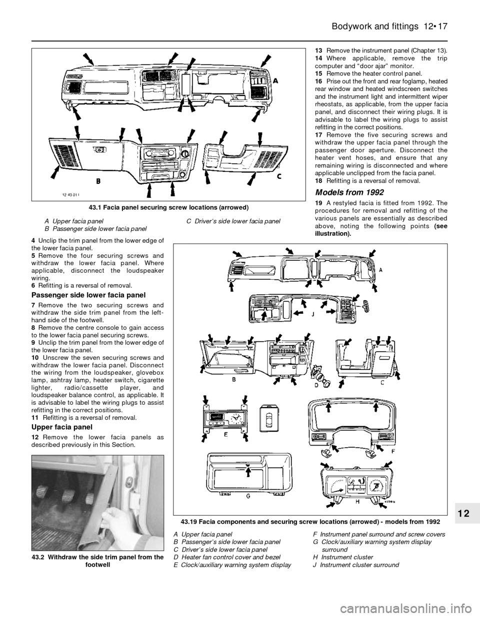
1Note the locations of the facia panel
securing screws (see illustration).
Disconnect the battery negative lead.
Driver’s side lower facia panel
2Remove the two securing screws and
withdraw the side trim panel from the right-
hand side of the footwell (see illustration).
3Remove the securing screws and unclip the
lower and upper steering column shrouds.
43Facia panels - removal and
refitting
42Cab interior trim panels
(P100 models) - removal and
refitting
12•16Bodywork and fittings
42.6 Cab interior rear panel fixings - P100
models
A Upper and lower trim panel fixings
B Jack handle retaining clips
C Lower trim panel fixings
41.21 Interior rear pillar trim panel fixings
(arrowed) - P100 models
A Upper trim panelB Lower trim panel
41.1 Interior pillar trim panel fixings - Hatchback models
A Front pillar trim panel
B1 Centre pillar upper trim panelB2 Centre pillar lower trim panel
C Rear pillar trim panel
Page 17 of 22

4Unclip the trim panel from the lower edge of
the lower facia panel.
5Remove the four securing screws and
withdraw the lower facia panel. Where
applicable, disconnect the loudspeaker
wiring.
6Refitting is a reversal of removal.
Passenger side lower facia panel
7Remove the two securing screws and
withdraw the side trim panel from the left-
hand side of the footwell.
8Remove the centre console to gain access
to the lower facia panel securing screws.
9Unclip the trim panel from the lower edge of
the lower facia panel.
10Unscrew the seven securing screws and
withdraw the lower facia panel. Disconnect
the wiring from the loudspeaker, glovebox
lamp, ashtray lamp, heater switch, cigarette
lighter, radio/cassette player, and
loudspeaker balance control, as applicable. It
is advisable to label the wiring plugs to assist
refitting in the correct positions.
11Refitting is a reversal of removal.
Upper facia panel
12Remove the lower facia panels as
described previously in this Section.13Remove the instrument panel (Chapter 13).
14Where applicable, remove the trip
computer and “door ajar” monitor.
15Remove the heater control panel.
16Prise out the front and rear foglamp, heated
rear window and heated windscreen switches
and the instrument light and intermittent wiper
rheostats, as applicable, from the upper facia
panel, and disconnect their wiring plugs. It is
advisable to label the wiring plugs to assist
refitting in the correct positions.
17Remove the five securing screws and
withdraw the upper facia panel through the
passenger door aperture. Disconnect the
heater vent hoses, and ensure that any
remaining wiring is disconnected and where
applicable unclipped from the facia panel.
18Refitting is a reversal of removal.
Models from 1992
19A restyled facia is fitted from 1992. The
procedures for removal and refitting of the
various panels are essentially as described
above, noting the following points(see
illustration).
Bodywork and fittings 12•17
1243.19 Facia components and securing screw locations (arrowed) - models from 1992
A Upper facia panel
B Passenger’s side lower facia panel
C Driver’s side lower facia panel
D Heater fan control cover and bezel
E Clock/auxiliary warning system displayF Instrument panel surround and screw covers
G Clock/auxiliary warning system display
surround
H Instrument cluster
J Instrument cluster surround
A Upper facia panel
B Passenger side lower facia panelC Driver’s side lower facia panel
43.1 Facia panel securing screw locations (arrowed)
43.2 Withdraw the side trim panel from the
footwell
Page 18 of 22

20On models with an adjustable steering
column, fully extend and lower the steering
column before attempting to remove any of
the panels on the driver’s side.
21The steering column shrouds are secured
by six screws - five through the lower shroud,
and one through the upper shroud.
22If necessary, remove the centre console.
23The driver’s side lower facia panel is
secured by five screws.
24The passenger’s side lower facia panel is
secured by eight screws.
25On models with an alarm, the alarm warning
light must be disconnected and removed before
removing the upper facia panel.
Models up to 1990
Full length console
1Where applicable, prise the electric window
switches from the front upper console panel
and disconnect the wiring.
2Remove the three securing screws from the
front upper console panel, then withdraw the
panel over the gear selector lever, at the same
time releasing the rubber gaiter where
applicable.
3On “high specification” models, where
applicable prise the electric window switches
from the rear upper console panel and
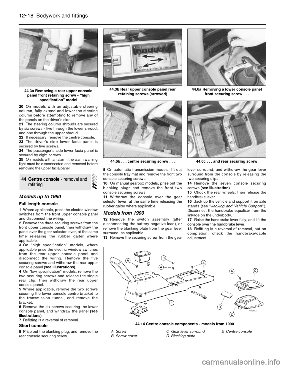
disconnect the wiring. Remove the five
securing screws and withdraw the rear upper
console panel (see illustrations).
4On “low specification” models, remove the
two securing screws and release the single
rear clip, then withdraw the rear upper
console panel.
5Where applicable, remove the two screws
securing the lower console centre bracket to
the transmission tunnel, and remove the
bracket.
6Remove the six screws securing the lower
console panel, and withdraw the panel (see
illustrations).
7Refitting is a reversal of removal.
Short console
8Prise out the blanking plug, and remove the
rear console securing screw.9On automatic transmission models, lift out
the console tray mat and remove the front two
console securing screws.
10On manual gearbox models, prise out the
blanking plugs and remove the front two
console securing screws.
11Withdraw the console over the gear
selector lever, at the same time releasing the
rubber gaiter where applicable.
Models from 1990
12Remove the switch assembly (after
disconnecting the battery negative lead), or
remove the blanking plate from the gear lever
surround, as applicable.
13Remove the securing screw from the gearlever surround, and withdraw the gear lever
surround from the console by releasing the
two securing clips.
14Remove the seven console securing
screws (see illustration).
15Chock the rear wheels, then release the
handbrake lever.
16Jack up the vehicle and support it on axle
stands (see “Jacking and Vehicle Support”).
Disconnect the handbrake equaliser from the
linkage on the underbody.
17Raise the handbrake lever fully, and lift the
console over the handbrake lever.
18Refitting is a reversal of removal, but on
completion, check the handbrake/cable
adjustment.
44Centre console - removal and
refitting
12•18Bodywork and fittings
44.3b Rear upper console panel rear
retaining screws (arrowed)
44.6b . . . centre securing screw . . .
44.14 Centre console components - models from 1990
A Screw
B Screw coverC Gear lever surround
D Blanking plateE Centre console
44.6c . . . and rear securing screw
44.6a Removing a lower console panel
front securing screw . . .44.3a Removing a rear upper console
panel front retaining screw - “high
specification” model